Table of Contents
Advertisement
Quick Links
Advertisement
Table of Contents

Related Manuals for AuCom MVS Series

Summary of Contents for AuCom MVS Series
- Page 1 PRODUCT G U I D E MVS SERIES SOFT STARTERS http://www.kontrolkalemi.com/forum/...
-
Page 2: Table Of Contents
CONTENTS Section 1 Caution Statements Section 2 General Description 2.1 Overview......................3 2.2 Feature List...................... 3 2.3 Type Codes ..................... 4 Section 3 Specifications 3.1 Current Ratings ....................5 3.2 Dimensions and Weights................. 6 3.3 General Technical Data................... 7 Section 4 Installation 4.1 Mounting Instructions –... -
Page 3: Caution Statements
CAUTION STATEMENTS Section 1 Caution Statements This symbol is used throughout this manual to draw attention to topics of special importance to the installation and operation of the MVS soft starter. Caution Statements cannot cover every potential cause of equipment damage but can highlight common causes of damage. -
Page 4: General Description
General Description 2.1 Overview The MVS Series provides compact and robust soft start solutions for control of medium voltage motors. MVS Series soft starters provide a complete range of motor and system protection features and have been designed for reliable performance in the most demanding installation situations. -
Page 5: Type Codes
GENERAL DESCRIPTION 2.3 Type Codes Control Supply Voltage C12 = 110 VAC & 230 VAC Supply Voltage V02 = 2300 VAC 50 / 60 Hz V03 = 3300 VAC 50 / 60 Hz V04 = 4160 VAC 50 / 60 Hz V06 = 6600 VAC 50 / 60 Hz V07 = 7200 VAC 50 / 60 Hz V11 = 11000 VAC 50 / 60 Hz... -
Page 6: Specifications
SPECIFICATIONS Section 3 Specifications 3.1 Current Ratings Two starts per hour 3.5-15:1785 4.0-20:1780 4.0-30:1770 5.0-30:1770 5.0-60:1740 40 °C 50 °C 40 °C 50 °C 40 °C 50 °C 40 °C 50 °C 40 °C 50 °C MVS-0080-xxx MVS-0159-xxx MVS-0230-xxx MVS-0321-xxx Three starts per hour 4.0-20:1180 4.0-30:1170... -
Page 7: Dimensions And Weights
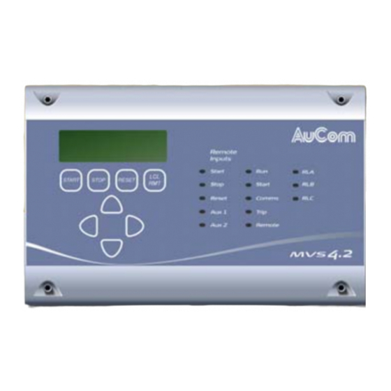
(61.38) (21.69) (478.40) MVS- xxxx-V07 Please contact your local supplier for dimensions for MVS-xxxx-V11. Controller The MVS controller is suitable for use with all models in the MVS Series. 340.0 54.0 (13.39) (2.13) mm (inch) Weight: 2.1 kg (4.63 lb) -
Page 8: General Technical Data
SPECIFICATIONS 3.3 General Technical Data Supply Mains Supply Voltage MVSxxxx-V02-xxx ............3 x 2300 VAC (± 10%) MVSxxxx-V03-xxx ............3 x 3300 VAC (± 10%) MVSxxxx-V04-xxx ............3 x 4160 VAC (± 10%) MVSxxxx-V06-xxx ............3 x 6600 VAC (± 10%) MVSxxxx-V07-xxx ............ - Page 9 SPECIFICATIONS Environmental Degree of Protection Power Assembly ..................IP00 Controller ................IP54 / NEMA 12 Motor Controller Panel (optional) ......designed to IP54 / NEMA 12 Operating Temperature ............. - 10 ˚C to + 60 ˚C Storage Temperature ..............- 25 ˚C to + 55 ˚C Humidity ..............
-
Page 10: Installation
Installation 4.1 Mounting Instructions – Power Assembly All models in the MVS Series have an IP00 rating and must be installed inside an enclosure. The power assembly should be installed with 100 mm clearance above for isolation; no clearance is required below or at the sides. -
Page 11: Mounting Instructions - Controller
INSTALLATION 4.2 Mounting Instructions – Controller The MVS controller can be secured in place with ten M4 nuts, affixed to the bolts on the back of the controller. 54.0 (2.13) 112 (4.41) 300 (11.81) 310 (12.20) 340 (13.39) To mount the controller, make a 186 mm x 300 mm cutout at the desired mounting location. -
Page 12: Power Terminations
INSTALLATION 4.3 Power Terminations T2, T2B, L2 T3, T3B, L3 (0.98) (0.24) (0.51) Rear of Unit inch inch (inch) inch inch inch inch inch inch MVS-xxxx-V02 MVS-xxxx-V03 (8.98) (3.11) (29.29) (3.11) (5.08) (7.05) (7.87) (7.87) (7.87) MVS-xxxx-V04 MVS-xxxx-V06 (8.98) (3.11) (31.65) (4.19) (6.46) -
Page 13: Control Terminations
INSTALLATION 4.4 Control Terminations Control wiring is secured in place by 3 mm spring terminals. Control Wiring (0.12) mm (inch) 4.5 Electrical Schematic Diagram 1: Electrical Schematic 3 PHASE TO MOTOR SUPPLY + 10 BYPASS CONTACTOR 110~130 VAC - 15 FEEDBACK SIGNAL + 10 220~240VAC... -
Page 14: Internal Wiring
INSTALLATION 4.6 Internal Wiring Diagram 2: Internal Wiring SERIES 710-03261-00A http://www.kontrolkalemi.com/forum/... -
Page 15: Overview
Please refer to the schematic drawings on pages 12, 13, 15 and 17 for details. 5.2 Main Contactor A main contactor is required in all MVS Series installations. The contactor should be selected such that the contactor's AC3 rating is greater than or equal to the full load current rating of the connected motor. - Page 16 POWER CIRCUITS Diagram 3: Standard Power Circuit Configuration MVS starter installation with main and bypass contactors. MOTOR BYPASS CONTACTOR CONTROL FEEDBACK SIGNAL SUPPLY K1M MAIN CONTACTOR K2M BYPASS CONTACTOR RUN OUTPUT (PFC) ITEM DESCRIPTION POWER ASSEMBLY CONTROL VOLTAGE TERMINAL BLOCK POWER INTERFACE PCB MAIN CONTACTOR BYPASS CONTACTOR...
-
Page 17: Main Isolator / Earth Switch
POWER CIRCUITS 5.4 Main Isolator / Earth Switch If specified, a main isolator/ earth switch can be connected upstream of the main contactor as shown in Diagram 4. The isolator interlocks the panel door to ensure personnel safety. 5.5 "R Rated" Protection Fuses If specified, "R Rated"... - Page 18 POWER CIRCUITS Diagram 4: Complete Power Circuit Configuration MVS Starter installation with main contactor, bypass contactor, isolator/earth switch, fuses and medium voltage control supply transformer. Configured for two-wire start/stop control. SERIES 710-03261-00A http://www.kontrolkalemi.com/forum/...
-
Page 19: Application Examples
APPLICATION EXAMPLES Section 6 Application Examples 6.1 Installation into a Panel The MVS panel permits a wide range of installation configurations. Power input and output can be top or bottom entry and power input can be provided from either cables or top horizontal bus bars. The diagrams below illustrate one possible configuration for installation. - Page 20 NOTES SERIES 710-03261-00A http://www.kontrolkalemi.com/forum/...
- Page 21 NOTES 710-03261-00A SERIES http://www.kontrolkalemi.com/forum/...
- Page 22 AuCom Electronics Limited 123 Wrights Road PO Box 21-245 Christchurch, New Zealand Phone: +64 3 338-8280 Fax: +64 3 338-8104 E-mail: salessupport@aucom.co.nz Internet: http://www.aucom.com http://www.kontrolkalemi.com/forum/...
Need help?
Do you have a question about the MVS Series and is the answer not in the manual?
Questions and answers