
Related Manuals for R-Tech MTS 255HF


Summary of Contents for R-Tech MTS 255HF
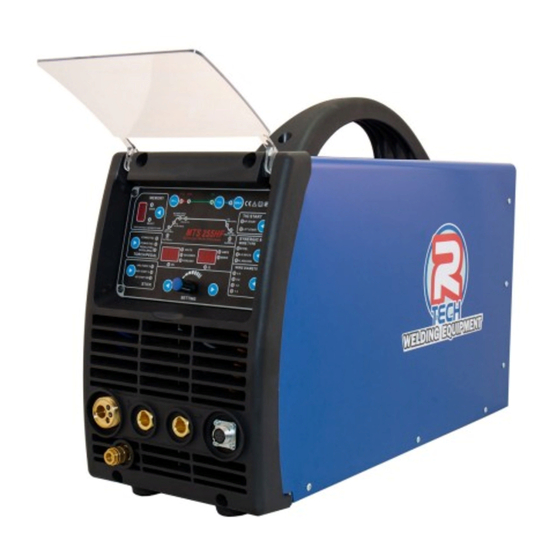
- Page 1 Tel: 01452 733933 Fax 01452 733939 MTS 255HF MIG-TIG-MMA WELDING MACHINE OPERATION INSTRUCTIONS Version 2020-10...
- Page 3 Thank you for selecting the R-Tech MTS255-HF Inverter MIG (Synergic) - MMA – HF DC TIG Welder. The MTS255-HF has many benefits over traditional transformer welders including infinite power control, adjustable arc force and features a heavy duty wire feed mechanism to provide very smooth wire feed and...
-
Page 4: Product Description
Welding Capability Duty Cycle The R-Tech MTS255-HF is rated at 250 Amps (MIG) at 35% duty cycle on a ten-minute basis. If the duty cycle is exceeded a thermal protector will shut machine off until the machine cools. -
Page 5: Installation
Installation Technical Specifications Model No. R-Tech MTS255-HF Input 240V 1 ~ AC 50/60Hz Operation Rated Input Current 32AMPS Rated Output Current 250 AMPS Duty Cycle 35% @ 40 250A (MIG/TIG) ,200A(MMA) Duty Cycle 100% @ 40 160A (MIG/TIG),130A(MMA) MIG: 30-250 AMPS... - Page 6 Transport & Unloading Never underestimate the weight of equipment, never move or leave suspended in the air above people. Always use recommended lifting equipment. WARNING! Falling Equipment can cause injury. Never lift welder with gas bottle attached. Never lift above personnel. Tilting Machine must be placed on a secure level surface or on a recommended undercarriage/trolley.
-
Page 7: Electric Shock Can Kill
Input Connections Make sure the voltage, phase and frequency of input power is as specified on machine rating plate located at rear of machine. Have a qualified electrician provide suitable input power as per national electrical codes. Make sure machine is earthed / grounded. -
Page 8: Controls And Settings
Controls and Settings Front Panel Fig 1 Voltage /MMA Arc-force/TIG down slope Display The meter on the front panel indicates the actual welding voltage or preset MIG voltage. Display 1, Volts, Seconds and Percent Current /Wire speed indicating The current indicating meter on the front panel indicates the actual welding current during the welding, indicates the wire speed during no welding. - Page 9 When the duty cycle has been exceeded or an over current condition will occur, the LED will light. Allow the unit to cool while running until the light goes off or for 10 minutes before resetting the welder. If the condition persists, check for loose wires or voltage supply problems or call R-Tech support. Memory channel LED This displays current memory job number 1 - 9 CH (channel) / SAVE &...
- Page 10 The 4T function in TIG mode acts similarly, but in conjunction with the up/down slope timer. As the torch trigger is pressed for the second time, the trigger should be held in until the downslope timer completes its cycle. The trigger may then be released to end the arc.
- Page 11 Rear machine connections Fig2 Mains input cable (240V AC input) Fit the required plug as per your electrical installation On/Off Switch Fuse Holder 5A fuse for wire speed motor Gas input connector Connect input gas hose ensuring connection is tight...
-
Page 12: Connections For Tig (Gtaw) Welding
Connections for TIG (GTAW) Welding Fig 3 Gas outlet Connect the TIG torch gas hose quick release connector MIG Torch Euro Connector (NOT used in TIG mode) Positive power connector + Connect the earth lead to by inserting and twisting until tight and the earth clamp to work/ bench Torch switch / Foot pedal socket Connect TIG torch control plug or Remote Foot Pedal plug Negative power connector -... - Page 13 Connections for MMA STICK (SMAW) Welding Gas outlet (NOT used in MMA mode) MIG Torch Euro Connector (NOT used in MMA mode) Positive power outlet – Connect electrode holder lead Remote connection (NOT used in MMA mode) Negative power outlet – Connect earth lead...
- Page 14 Connections for MIG Welding Gas outlet (NOT used in MIG mode) MIG Torch Euro Connector - Connect MIG Torch. When using Spool Gun for aluminium welding connect torch here and 7 pin plug to socket (4) Positive - Not normally used unless using gasless wire (reverse polarity) Remote connection (NOT used in MIG mode) If using Spool-On Gun, connect the 7-pin plug here.
- Page 15 To reverse the roller, remove the thumb screw securing the drive roll. Pull the drive roll off and flip the drive roll over. Reassemble and tighten roller. If larger roller is needed, contact R-Tech. Be careful to replace the woodruff key between outer roller and shaft.
- Page 16 Connections for using gas / gasless wire Ensure machine is disconnected from mains before changing torch polarity When welding with gasless wire you need to reverse the polarity of welding power. Gas welding is negative earth and positive wire (torch) Gasless welding is positive earth and negative wire (torch) 1.
-
Page 17: Operation
Operation SAFETY PRECAUTIONS WARNING! ELECTRIC SHOCK CAN KILL Do not touch electrically live parts or electrode with skin or wet clothing. Insulate yourself from work and ground Always wear dry insulating gloves WARNING! FUMES AND GASES can be dangerous Keep your head out of fumes & gases produced from welding. Use ventilation or exhaust to remove fumes &... - Page 18 Welding in MIG STD (Manual) Mode Connect the MIG Torch to machine, connect earth lead to machine & work piece. Fit wire reel to machine using guide on page 15 Connect welding gas and set flow to approx. 12-14 LPM Set the machine mode to MIG STD (No.
- Page 19 Welding in MIG SYN (Synergic) Mode Connect the MIG Torch to machine, connect earth lead to machine & work piece. Fit wire reel to machine using guide on page 15 Connect welding gas and set flow to approx. 12-14 LPM Set the machine mode to MIG SYN (No.
- Page 20 adjustment to suit your welding style / requirements. Select MIG voltage (MIG volts LED lit) an adjust voltage to suit. See Page 24 for more information. More wire / Less voltage = Dip transfer Less wire / More voltage = Spray transfer...
- Page 21 Welding in MIG STD (Manual) Mode with SPOOL GUN Connect the MIG SPOOL Torch to machine, connect earth lead to machine & work piece. Fit wire reel to spool gun and ensure tip is correct for wire size. Connect welding gas and set flow to approx. 12-14 LPM – For aluminum welding you require 100% pure argon. Set the machine mode to MIG STD (No.
- Page 22 Welding in TIG mode - No remote foot pedal Connect the TIG torch and earth lead to machine & work piece. Connect Argon gas and set flow to approx. 8 LPM Set the machine mode to TIG (No. 7 front panel) Select 2T or 4T torch operation.
- Page 23 Welding in TIG mode - with Remote foot pedal Connect the TIG Torch to machine, connect earth lead to machine & work piece. Connect remote foot pedal to machine Connect Argon gas and set flow to approx. 8 LPM Set the machine mode to TIG (No. 7 front panel) Select PEDAL in torch/pedal section (No.
-
Page 24: Welding In Stick Mma (Smaw) Mode
Welding in STICK MMA (SMAW) Mode Fit MMA electrode holder to machine – Normally positive terminal Fit earth lead to machine and to work piece – Normally negative terminal Set the machine mode to MMA (No. 7 front panel) Press button in STICK section (No.14) to select function required, this will be shown in display (1) and can be adjusted with knob (18) ARC Force % - This controls the arc response to when electrode is held close/away from workpiece. -
Page 25: Synergic And Basic Mig Operation
SYNERGIC AND BASIC MIG OPERATION Synergic vs. Manual Setup and Operation Synergic MIG operation: The Synergic function of the MIG (255HF) component allows the user to only need to use the wire feed speed control to make the unit operate. The welder is programmed to automatically adjust the voltage based on the users input of wire diameter and filler metal type when the wire speed is increased or decreased by turning the wire speed adjustment knob. -
Page 26: Maintenance
The second column labeled possible cause lists the obvious external possibilities that may contribute to the machine symptom Step 3. Recommended course of action This column provides a course of action for the possible cause, generally it states to contact R-Tech welding for repair of machine. - Page 27 4.Thermostat broken 4.Change the thermostat(JUC-OF) 1.IGBT broken 2.Output diode broken 4.Over-current light 3.Drive plate broken ON (warning led lights Contact R-Tech green color) 4.Control plate broken 5.Over current welding 1.The fuse broken 1.Change the fuse 5A/250V 2.Potentiometer wiring faulty (on left panel, open wire feeder case) 5.Wire feeder not...
- Page 28 - 25 -...
- Page 29 - 26 -...
Need help?
Do you have a question about the MTS 255HF and is the answer not in the manual?
Questions and answers