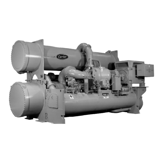
Carrier 17EX Start-Up, Operation And Maintenance Instructions Manual
Externally geared centrifugal liquid chillers
Hide thumbs
Also See for 17EX:
- Start-up, operation and maintenance instructions manual (437 pages) ,
- Start up & operation manual (116 pages)
Table of Contents
Advertisement
Start-Up, Operation, and Maintenance Instructions
Centrifugal liquid chillers are designed to provide safe
and reliable service when operated within design speci-
fications. When operating this equipment, use good judg-
ment and safety precautions to avoid damage to equip-
ment and property or injury to personnel.
Be sure you understand and follow the procedures and
safety precautions contained in the chiller instructions
as well as those listed in this guide.
DO NOT VENT refrigerant relief valves within a building. Outlet
from rupture disc or relief valve must be vented outdoors in ac-
cordance with the latest edition of ASHRAE (American Society of
Heating, Refrigeration, and Air Conditioning Engineers) 15. The
accumulation of refrigerant in an enclosed space can displace oxy-
gen and cause asphyxiation.
PROVIDE adequate ventilation in accordance with ASHRAE 15,
especially for enclosed and low overhead spaces. Inhalation of high
concentrations of vapor is harmful and may cause heart irregulari-
ties, unconsciousness, or death. Misuse can be fatal. Vapor is heavier
than air and reduces the amount of oxygen available for breathing.
Product causes eye and skin irritation. Decomposition products are
hazardous.
DO NOT USE OXYGEN to purge lines or to pressurize a chiller
for any purpose. Oxygen gas reacts violently with oil, grease, and
other common substances.
NEVER EXCEED specified test pressures, VERIFY the allowable
test pressure by checking the instruction literature and the design
pressures on the equipment nameplate.
DO NOT USE air for leak testing. Use only refrigerant or dry
nitrogen.
DO NOT VALVE OFF any safety device.
BE SURE that all pressure relief devices are properly installed and
functioning before operating any machine.
DO NOT WELD OR FLAME CUT any refrigerant line or vessel
until all refrigerant (liquid and vapor) has been removed from chiller.
Traces of vapor should be displaced with dry air or nitrogen and
the work area should be well ventilated. Refrigerant in contact with
an open flame produces toxic gases.
DO NOT USE eyebolts or eyebolt holes to rig chiller sections or
the entire assembly.
DO NOT work on high-voltage equipment unless you are a quali-
fied electrician.
DO NOT WORK ON electrical components, including control pan-
els, switches, starters, or oil heater until you are sure ALL POWER
IS OFF and no residual voltage can leak from capacitors or solid-
state components.
LOCK OPEN AND TAG electrical circuits during servicing. IF WORK
IS INTERRUPTED, confirm that all circuits are deenergized be-
fore resuming work.
AVOID SPILLING liquid refrigerant on skin or getting it into the
eyes. USE SAFETY GOGGLES. Wash any spills from the skin
with soap and water. If any enters the eyes, IMMEDIATELY FLUSH
EYES with water and consult a physician.
NEVER APPLY an open flame or live steam to a refrigerant cyl-
inder. Dangerous overpressure can result. When necessary to heat
refrigerant, use only warm (110 F [43 C]) water.
Manufacturer reserves the right to discontinue, or change at any time, specifications or designs without notice and without incurring obligations.
Book 2
PC 211
Catalog No. 531-721
Tab
5d
Externally Geared Centrifugal Liquid Chillers
1500 to 2250 Nominal Tons (5280 to 7910 kW)
SAFETY CONSIDERATIONS
DO NOT REUSE disposable (nonreturnable) cylinders or
attempt to refill them. It is DANGEROUS AND ILLEGAL. When
cylinder is emptied, evacuate remaining gas pressure, loosen
the collar and unscrew and discard the valve stem. DO NOT
INCINERATE.
CHECK THE REFRIGERANT TYPE before adding refrigerant to
the chiller. The introduction of the wrong refrigerant can cause dam-
age or malfunction to this chiller.
Operation of this equipment with refrigerants other than those
cited herein should comply with ASHRAE-15 (latest edition). Con-
tact Carrier for further information on use of this chiller with other
refrigerants.
DO NOT ATTEMPT TO REMOVE fittings, covers, etc., while chiller
is under pressure or while chiller is running. Be sure pressure is at
0 psig (0 kPa) before breaking any refrigerant connection.
CAREFULLY INSPECT all relief devices, rupture discs, and other
relief devices AT LEAST ONCE A YEAR. If chiller operates in a
corrosive atmosphere, inspect the devices at more frequent
intervals.
DO NOT ATTEMPT TO REPAIR OR RECONDITION any relief
device when corrosion or build-up of foreign material (rust, dirt,
scale, etc.) is found within the valve body or mechanism. Replace
the device.
DO NOT install relief devices in series or backwards.
USE CARE when working near or in line with a compressed spring.
Sudden release of the spring can cause it and objects in its path to
act as projectiles.
RUN WATER PUMPS when removing, transferring, or charg-
ing refrigerant.
DO NOT STEP on refrigerant lines. Broken lines can whip about
and cause personal injury.
DO NOT climb over a chiller. Use platform, catwalk, or staging.
Follow safe practices when using ladders.
USE MECHANICAL EQUIPMENT (crane, hoist, etc.) to lift or
move inspection covers or other heavy components. Even if com-
ponents are light, use such equipment when there is a risk of slip-
ping or losing your balance.
BE AWARE that certain automatic start arrangements CAN EN-
GAGE THE STARTER. Open the disconnect ahead of the starter
in addition to shutting off the machine or pump.
USE only repair or replacement parts that meet the code require-
ments of the original equipment.
DO NOT VENT OR DRAIN waterboxes containing industrial brines,
liquid, gases, or semisolids without permission of your process con-
trol group.
DO NOT LOOSEN waterbox cover bolts until the waterbox has
been completely drained.
DOUBLE-CHECK that coupling nut wrenches, dial indicators, or
other items have been removed before rotating any shafts.
DO NOT LOOSEN a packing gland nut before checking that the
nut has a positive thread engagement.
PERIODICALLY INSPECT all valves, fittings, and piping for cor-
rosion, rust, leaks, or damage.
PROVIDE A DRAIN connection in the vent line near each pres-
sure relief device to prevent a build-up of condensate or rain
water.
Printed in U.S.A.
Form 17EX-1SS
Pg 1
17EX
50/60 Hz
7-97
Replaces: New
Advertisement
Table of Contents
Troubleshooting

Related Manuals for Carrier 17EX


Summary of Contents for Carrier 17EX
-
Page 1: Safety Considerations
Operation of this equipment with refrigerants other than those cited herein should comply with ASHRAE-15 (latest edition). Con- tact Carrier for further information on use of this chiller with other refrigerants. DO NOT ATTEMPT TO REMOVE fittings, covers, etc., while chiller is under pressure or while chiller is running. -
Page 2: Table Of Contents
....... ABBREVIATIONS 17EX CHILLER FAMILIARIZATION .... - Page 3 ....Carrier Comfort Network Interface ....... . .
- Page 4 • INSTALLATION OF NEW PSIO MODULE PHYSICAL DATA AND WIRING SCHEMATICS INDEX INITIAL START-UP CHECKLIST FOR 17EX EXTERNALLY GEARED CENTRIFUGAL LIQUID CHILLER ......
-
Page 5: Introduction
REFRIGERATION CYCLE (Fig. 3) The 17EX chiller can be used to chill either water or brine. The data in this book applies to either application. Appli- cations using corrosive brines may require using special tubes, tubesheet, and waterbox materials which are special order items. - Page 6 LEGEND NIH — Nozzle-In-Head *Any available cooler size can be combined with any available condenser size. NOTE: For details on motor size designations, see below. ASME ARI (Air Conditioning ‘U’ STAMP and Refrigeration Institute) PERFORMANCE CERTIFIED (60 Hz Only) Fig. 1 — Model Number Identification...
- Page 7 19 — Refrigerant Liquid Line to Cooler 20 — Power Panel 21 — Oil Level Sight Glasses (2) 17EX WITH EXTERNAL GEAR (SPEED INCREASER) Fig. 2 — Typical 17EX Chiller Components LEGEND 22 — Oil Drain and Charging Valve 23 — Oil Heater (Hidden) 24 —...
-
Page 8: Oil Cooling Cycle
The chiller compressor continuously draws large quanti- ties of refrigerant vapor from the cooler at a rate determined by the amount of guide vane opening. This compressor suc- tion reduces the pressure within the cooler, allowing the liq- uid refrigerant to boil vigorously at a fairly low temperature (typically 38 to 42 F [3 to 6 C]). -
Page 9: External Gear Lubrication Cycle
(Item 1) during operation. Oil from both circuits re- turns by gravity to the reservoir. All starters, whether supplied by Carrier or the customer, must meet Carrier Starter Specification Z-375. This speci- fication can be obtained from a Carrier Sales Representa- tive. - Page 10 OIL COOLER/ FILTER TO PIC CONTROLLER PLUG VALVE SIGHT GLASSES TO POWER PANEL OIL PUMP & PRESS. REGULATOR Fig. 4 — 17EX Compressor Lubrication Cycle SHAFT DISPLACEMENT & BRG TEMP. CUTOUT CONNECTIONS THRUST BEARING MAIN OIL RESERVOIR DRAIN & THERMISTOR HEATER...
-
Page 11: Controls
13 — Oil Cooler 14 — Plug Valve General — The 17EX externally geared open-drive cen- trifugal liquid chiller contains a microprocessor-based con- trol center that monitors and controls all operations of the chiller. The microprocessor control system matches the cool- ing capacity of the chiller to the cooling load while provid- ing state-of-the-art chiller protection. -
Page 12: Pic System Components
See Fig. 6-10 for the lo- cations of sensors, transducers, and other devices controlled and/or monitored by the PIC system. The PIC can be interfaced with the Carrier Comfort Network (CCN) if desired. It can communicate with other PIC-equipped chillers and other CCN devices. - Page 13 Temperature Sensor 15 — Condenser Entering and Leaving Water Temperature Cable 16 — Oil Suction Pressure Sensor Fig. 6 — 17EX Controls and Sensor Locations (cont) 17 — Oil Pump Conduit 18 — Oil Pump Sensor 19 — PIC Control Panel 20 —...
- Page 14 Fig. 6 — 17EX Controls and Sensor Locations (cont) Fig. 7 — Control Sensors (Temperature) Fig. 8 — Control Sensors (Pressure Transducer, Typical) LEGEND — Local Interface Device — Product Integrated Controls PSIO — Processor Sensor Input/Output Module 1 — Optional 8-Input Module for Spare Inputs to Control Interface (One of Two Available) 2 —...
- Page 15 LEGEND EQUIP GND — Equipment Ground — Ground — Motor TEWAC — Totally Enclosed Water-to- Air Cooled Fig. 10 — 17EX Chiller Power Panel and Controls Connections...
-
Page 16: Six-Pack Relay Board
PROCESSOR/SENSOR INPUT/OUTPUT MODULE (PSIO) — This module contains all the operating software needed to control the chiller. The 17EX uses 5 pressure transducers and 8 thermistors to sense pressures and temperatures. These inputs are connected to the PSIO module. The PSIO also... -
Page 17: Lid Default Screen Menu Items
NOTE: When an alarm is detected, the LID default screen freezes (stops updating) at the time of alarm. The freeze en- ables the operator to view the chiller conditions at the time of the alarm. The status tables show the updated informa- tion. -
Page 18: Override Operations
3. Press SELECT to view the desired Point Status table. 4. On Point Status table PREVIOUS until desired point is displayed on the screen. For Discrete Points — Press START or STOP , YES or NO , ON or OFF , etc. to select the desired state. - Page 19 SELECT NEXT Modify a Schedule Time INCREASE ENTER DECREASE Add/Eliminate a Day ENABLE DISABLE ENTER Fig. 15 — 17EX LID Menu Structure List the Service Tables • Base Demand Limit • LCW Setpoint • ECW Setpoint • Ice Build Setpoint...
- Page 20 Select a Parameter PREVIOUS NEXT Modify a Parameter INCREASE DECREASE DISABLE ENABLE Fig. 16 — 17EX Service Menu Structure List the Control Tests • Automated Test • PSIO Thermistors • Options Thermistor • Transducers • Guide Vane Actuator • Pumps •...
- Page 21 — Motor Voltage, RLA, and Frequency — Starter Type — Condenser Freeze Safety — Soft Stop Configuration — Start to Stop Timer — Gear Oil Pump Configuration Fig. 16 — 17EX Service Menu Structure (cont) SELECT EXIT SELECT EXIT ENTER...
-
Page 22: To View And Change Set Points
Service Operation, see the Service Op- eration section, page 42. For examples of LID display screens, see Table 2. LEGEND FOR TABLE 2 — LID DISPLAY DATA — Carrier Comfort Network CHWR — Chilled Water Return CHWS — Chilled Water Supply Compr — Compressor —... - Page 23 *Compressor Motor kW †Information is applicable to hermetic chillers (19EX) only. **Oil pressure is read directly from a differential pressure module on 17EX chillers. NOTE: values preceded by an asterisk (*) can be forced (changed by an operator) from the LID screen or from another control device (such as a Carrier Comfort Network [CCN] terminal).
- Page 24 NOTE: values preceded by an asterisk (*) can be forced (changed by an operator) from the LID screen or from another control device (such as a Carrier Comfort Network [CCN] terminal). To access this display from the LID default screen: 1.
- Page 25 To access this display from the LID default screen: 1. Press MENU 2. Press STATUS . 3. Scroll down to highlight STATUS04. 4. Press SELECT . DESCRIPTION Main Gear Oil Pump Auxiliary Gear Oil Pump Gear Oil Pressure Gear Oil Temperature To access this display from the LID default screen: 1.
- Page 26 EXAMPLE 6 — CONFIGURATION (CONFIG) DISPLAY SCREEN To access this display from the LID default screen: 1. Press MENU 2. Press SERVICE . 3. Scroll down to highlight EQUIPMENT CONFIGURATION. 4. Press SELECT . 5. Scroll down to highlight CONFIG. 6.
- Page 27 EXAMPLE 7 — LEAD/LAG CONFIGURATION DISPLAY SCREEN To access this display from the LID default screen: 1. Press MENU 2. Press SERVICE . 3. Scroll down to highlight EQUIPMENT CONFIGURATION. 4. Press SELECT . 5. Scroll down to highlight LEAD/LAG. 6.
- Page 28 To access this display from the LID default screen: 1. Press MENU 2. Press SERVICE . 3. Scroll down to highlight EQUIPMENT SERVICE. 4. Press SELECT . 5. Scroll down to highlight SERVICE1. 6. Press SELECT . DESCRIPTION CONFIGURABLE RANGE Motor Temp Override* 150-200 (66-93) Cond Press Override...
- Page 29 To access this display from the LID default screen: 1. Press MENU 2. Press SERVICE . 3. Scroll down to highlight EQUIPMENT SERVICE. 4. Press SELECT . 5. Scroll down to highlight SERVICE2. 6. Press SELECT . DESCRIPTION OPTIONS BOARD 1 20 mA POWER CONFIGURATION External = 0, Internal = 1 RESET 20 mA Power Source...
- Page 30 EXAMPLE 11 — MAINTENANCE (MAINT01) DISPLAY SCREEN To access this display from the LID default screen: 1. Press MENU 2. Press SERVICE . 3. Scroll down to highlight CONTROL ALGORITHM STATUS. 4. Press SELECT . 5. Scroll down to highlight MAINT01. DESCRIPTION CAPACITY CONTROL Control Point...
- Page 31 EXAMPLE 13 — MAINTENANCE (MAINT03) DISPLAY SCREEN To access this display from the LID default screen: 1. Press MENU 2. Press SERVICE . 3. Scroll down to highlight CONTROL ALGORITHM STATUS. 4. Press SELECT . 5. Scroll down to highlight MAINT03. 6.
-
Page 32: Pic System Functions
PIC System Functions NOTE: In the rest of this manual, words not part of para- graph headings and printed in all capital letters can be viewed on the LID (e.g., LOCAL, CCN, RUNNING, ALARM, etc.). Words printed both in capital letters and italics can also be viewed on the LID and are parameters (CONTROL MODE, COOLING SETPOINT, OVERRIDE THRESHOLD, etc.) with associated values (e.g., modes, temperatures, pressures, per-... -
Page 33: Safety Controls
NOTE: This schedule is for illustration only, and is not in- tended to be a recommended schedule for chiller operation. Depending on its operating mode, the chiller uses the fol- lowing occupancy schedules: • LOCAL mode — Occupancy Schedule 01(OCCPC01 on the SCHEDULE screen). - Page 34 Operate water pumps with chiller off. Manually reduce water flow and observe switch for proper cutout. Safety shutdown occurs when cutout time exceeds 3 seconds. Carrier Part No. HK06ZC033 LIMIT –40 to 245 F (–40 to 118.3 C) 0.08 to 0.98 Voltage Ratio 220 F (104.4 C)
-
Page 35: Capacity Override
2. The motor load ramp loading rate is an operator-configured value that limits the rate at which the compressor motor current or compressor motor load increases. (LOAD PULL- DOWN %/MIN on the CONFIG screen). To select the ramp type, highlight the SELECT RAMP TYPE parameter on the CONFIG screen and select either 0 (TEMP) or 1 (LOAD). -
Page 36: Oil Cooler
Oil Cooler — The oil for the external gear and the com- pressor must be cooled while the compressor is running. The compressor oil cooler is a water-cooled, helical, tube-in- shell type heat exchanger. A plug valve is manually set to maintain proper temperatures. -
Page 37: Water/Brine Reset
Water/Brine Reset — Three types of chilled water/ brine reset are available, Reset Type 1, Reset Type 2, and Reset Type 3. They can be viewed or modified on the CON- FIG screen (accessed from the EQUIPMENT CONFIGU- RATION table). See Table 2, Example 6. The LID default screen status message indicates when a reset is active. -
Page 38: Surge Protection
T = (ECW) − (LCW) — Entering Chilled Water HGBP — Hot Gas Bypass — Leaving Chilled Water Fig. 19 — 17EX Hot Gas Bypass/Surge Prevention With Default Settings (SI) Surge Protection — Compressor surge can be de- tected by the PIC based on operator configured settings. Surge causes amperage fluctuations of the compressor motor. -
Page 39: Lead/Lag Operation
LEAD/LAG OPERATION — The PIC control has the ca- pability to operate 2 chillers in the lead/lag mode. It also has the additional capability to start a designated standby chiller when either the lead or lag chiller is not operating and capacity requirements are not being met. -
Page 40: Faulted Chiller Operation
FAULTED CHILLER OPERATION — If the lead chiller shuts down because of an alarm (*) condition, it stops com- municating with the lag and standby chillers. After 30 sec- onds, the lag chiller becomes the acting lead chiller and starts and stops the standby chiller, if necessary. -
Page 41: Temperature Control During Ice Build
TEMPERATURE CONTROL DURING ICE BUILD —During ice build, the capacity control algorithm uses the WATER/BRINE CONTROL POINT minus 5 F (2.7 C) to con- trol the LEAVING CHILLED WATER temperature. The ECW CONTROL OPTION (see CONFIG screen), the 20 mA DEMAND LIMIT, and any temperature reset option are ig- nored during ice build. -
Page 42: Service Operation
NOTE: The LID does not automatically re-attach to the PSIO module on the chiller. Access the ATTACH TO NETWORK DEVICE table, scroll to LOCAL, and press the ATTACH softkey to upload the local device. The software for the local chiller will now be uploaded. Service Operation —... -
Page 43: Start-Up/Shutdown/Recycle Sequence
7. Press SELECT to access the holiday table. The LID screen now shows the holiday start month and day, and how many days the holiday period will last. See Fig. 24. 8. Press NEXT or PREVIOUS to highlight HOLIDAY START MONTH, START DAY, or DURATION. 9. -
Page 44: Shutdown Sequence
If any of these requirements are not met, the PIC aborts the start and displays the applicable pre-start mode of failure on the LID default screen. A pre-start failure does not ad- vance the STARTS IN 12 HOURS counter (STATUS01 screen). Any failure after the 1CR relay has energized causes a safety shutdown, advances the STARTS IN 12 HOURS counter by one, and displays the applicable shutdown status on the LID... -
Page 45: Safety Shutdown
Safety Shutdown — A safety shutdown is identical to a manual shutdown with the exception that the LID displays the reason for the shutdown, the alarm light blinks continu- ously, and the spare alarm contacts are energized. A safety shutdown requires that the RESET softkey be pressed in order to clear the alarm. -
Page 46: Motor Auxiliary Devices
Check Chiller Tightness — Figure 25 outlines the proper sequence and procedures for leak testing. 17EX chillers may be shipped with the refrigerant con- tained in the economizer/storage vessel and the oil charge shipped in the compressor. The cooler/condenser vessels have a 15 psig (103 kPa) refrigerant charge. - Page 47 Fig. 25 — 17EX Leak Test Procedures...
- Page 48 Table 5A — HFC-134a Pressure — Temperature (F) TEMPERATURE (F) PRESSURE (psi) Table 5B — HFC-134a Pressure — Temperature (C) TEMPERATURE (C) 6.50 7.52 8.60 9.66 10.79 11.96 13.17 14.42 15.72 17.06 18.45 19.88 21.37 22.90 24.48 26.11 27.80 29.53 31.32 33.17 35.08...
-
Page 49: Standing Vacuum Test
4. Leak Determination — If an electronic leak detector in- dicates a leak, use a soap bubble solution, if possible, to confirm it. Total all leak rates for the entire chiller. Leak- age for the entire chiller at rates greater than the EPA (En- vironmental Protection Agency) guidelines or local codes must be repaired. -
Page 50: Inspect Water Piping
Refer to the piping diagrams provided in the certified drawings and the piping instruc- tions in the 17EX Installation Instructions manual. Inspect the piping to the cooler and condenser. Be sure that flow directions are correct and that all piping specifications have been met. -
Page 51: Motor Pre-Start Checks
2. The viscosity of the oil must be 68 ISO. Use of Carrier oil, specification PP16-2 is approved (Mobil DTE Heavy Medium or Texaco Regal UR & 068; Carrier Part No. - Page 52 Fig. 27 — External Gear Lubrication System...
-
Page 53: Carrier Comfort Network Interface
Carrier Comfort Network Interface — Comfort Network (CCN) communication bus wiring is sup- plied and installed by the electrical contractor. It consists of shielded, 3-conductor cable with drain wire. -
Page 54: Compressor Oil Charge
As you configure the 17EX chiller, write down all con- figuration settings. A log, such as the one shown on pages CL-1 to CL-12, is a convenient way to list configuration values. - Page 55 5. After the last digit is changed, the LID goes to the BUS # parameter. Press the EXIT softkey to leave the screen, record your password change, and return to the SERVICE menu. BE SURE TO REMEMBER YOUR PASSWORD. Retain a copy of the password for future reference. If you forget your password, you will not be able to access the SERVICE menu unless you install and download a new PSIO module.
-
Page 56: Check Pumpout System Controls And Optional Pumpout Compressor
SARY — The EQUIPMENT CONFIGURATION table has a number of screens to select, view, and/or modify. See Fig. 16 for the menu structure of this table. Carrier provides certified drawings that have the configuration values re- quired for specific jobsites. Modify these values only if requested. -
Page 57: High Altitude Locations
15 psig (103 kPa). Evacu- ate the entire chiller, and charge chiller from refrigerant cylinders. The full refrigerant charge on the 17EX will vary with chiller components and design conditions as indicated on the job data specifications. An approximate charge may be found in Physical Data and Wiring Schematics section, page 99. -
Page 58: Manual Operation Of The Guide Vanes
3. Chiller is charged with refrigerant and all refrigerant and all oil valves are in their proper operating position. 4. Gear oil, compressor oil, and motor bearing oil are at the proper levels in the reservoir sight glasses. 5. Compressor oil reservoir temperature is above 140 F (60 C) or refrigerant temperature plus 50°... -
Page 59: Disc Coupling Installation And Alignment
Under normal conditions, for the self-lubricating bear- ing, the rate of temperature rise should be from 20° to 25° F (11° to 14° C) during the first 10 minutes after starting up and approximately 40° F (22° C) over 30 minutes. The rate of bearing temperature rise is a function of the natural ventilation and operating conditions. - Page 60 2. Offset and Angular Alignment — Reverse dial indication or optical methods of alignment (such as lasers) are rec- ommended. A cold alignment and a hot check (with cor- rections, if necessary) are required. The hub flange OD can be used to mount the alignment equipment and is ma- chined to be concentric to the coupling bore.
-
Page 61: Check Oil Pressure And Compressor Stop
67. A clamping tool, Part No. TS-170, is available for check- ing alignment without disassembling the couplings. Check with your local Carrier representative. Never operate the compressor or drive with the cou- pling guards removed. Serious injury can result from contact with rotating equipment. -
Page 62: Initial Start-Up
Instruct the Operator — Check to be sure that the op- erator(s) understands all operating and maintenance proce- dures. Point out the various chiller parts and explain their function as part of the complete system. COOLER-CONDENSER — Relief devices, temperature sen- sor locations, pressure transducer locations, Schrader fit- tings, waterboxes and tubes, and vents and drains. -
Page 63: After Limited Shutdown
Fig. 31. It is possible to au- tomatically record PIC data by using CCN devices such as the Data Collection module and a Building Supervisor ter- minal. Contact your Carrier representative for more information. PUMPOUT AND REFRIGERANT TRANSFER Preparation —... - Page 64 REFRIGERATION LOG CARRIER 17EX EXTERNALLY GEARED CENTRIFUGAL CHILLER Plant Chiller Model No. REC. 1 TIME DATE OPERATOR INITIALS COOLER Refrigerant Pressure Temperature Water Pressure In Pressure Out Pressure GPM Temperature In Temperature Out CONDENSER Refrigerant Pressure Temperature Water Pressure In...
- Page 65 NOTE: Location of pumpout compressor may vary depending on ma- chine arrangement. COOLER ISOLATION DRIVE END VALVE Fig. 32 — Pumpout Unit Location and Valve Number Locations 11 CHILLER CHARGER VALVE REAR VIEW COMPRESSOR END...
-
Page 66: Transferring Refrigerant Into The Economizer/Storage Vessel
VENT VALVE VALVES VALVES CONDENSER WATER CONNECTIONS CONDENSER (FIELD PIPING) DISCHARGE VALVE Fig. 34 — Optional Pumpout Compressor 2. To determine economizer/storage vessel pressure, attach a 30 in.-0-400 psi (-101-0-2760 kPa) gage to the vessel. 3. Refer to Fig. 32 for valve locations and numbers. Transfer, addition, or removal of refrigerant in spring- isolated chillers may place severe stress on external pip- ing if springs have not been blocked in both up and down... -
Page 67: Procedures
PIC, they must be controlled manually. Removing Refrigerant — out system is used, the 17EX refrigerant charge may be trans- ferred into the economizer/storage vessel or another storage vessel. Follow procedures in the Pumpout and Refrigerant Transfer Procedures section when removing or transferring refrigerant. -
Page 68: Repair The Leak, Retest, And Apply Standing Vacuum Test
Refrigerant HFC-134a MUST NOT be mixed with air or oxygen and pressurized for leak testing. In general, this refrigerant should not be allowed to be present with high concentrations of air or oxygen above atmo- spheric pressures, because the mixture can undergo combustion. - Page 69 LEGEND — Lubricating Tube 2A — O-Ring 2B — O-Ring — Seal Housing — Coupling Guard Mounting Ring — Plain ⁄ -in. Washer (8 Required) — Hex Head Bolt, ⁄ -13 × 4 lg (8 Required) — Windage Baffle — Shaft End Labyrinth —...
- Page 70 9. Place a clean, lint-free cloth on a smooth, sturdy work surface. Place the seal housing assembly on the cloth with the face of the contact sleeve in contact with the cloth. While one person pushes down on the housing to compress the spring, another person must remove the snap ring.
-
Page 71: Chiller Alignment
Chiller Alignment ALIGNMENT METHODS — There are several established procedures for aligning shafts. The dial indicator method is presented here since it is considered to be one of the most accurate and reliable. Another faster and easier method for alignment involves using laser alignment tools and comput- ers. - Page 72 2. Parallel in elevation — This alignment is also made with shims, but it cannot be made while there is angular mis- alignment in elevation. 3. Angular in plan — This position can easily be lost if placed ahead of the two adjustments in elevation. 4.
- Page 73 If the larger opening remains the same but changes from side to side, the shafts are in perfect alignment. The change in opening is due entirely to coupling runout, as above, or to a burr or other damage to the coupling face. If the larger opening remains the same, and remains on the same side, the amount is entirely shaft (net) misalignment.
- Page 74 4. Loosen all holddown bolts except the pivot bolt. Turn the screw jack until the rear end of the equipment moves against the indicator by the desired amount. 5. Tighten the holddown bolts and recheck the indicator. If the reading has changed, loosen the three bolts and re- adjust.
- Page 75 Fig. 42 — Correcting Parallel Misalignment When using brackets, the diameter in the alignment for- mula (see Near Final Alignment, Connecting Angular Mis- alignment section) will be that of the circle through which the dial indicator rotates. 1. Shut down the chiller. 2.
-
Page 76: Weekly Maintenance
If additional oil is required, add oil as de- scribed in the Oil Changes section on page 77. The added oil must meet Carrier specifications. (See Table 11.) Do not over- fill the reservoir. Any additional oil added or removed should be logged by noting the amount and date. -
Page 77: Oil Specifications
Oil should be visible in the reservoir sight glass during all operating and shutdown conditions. EXTERNAL GEAR OIL FILTER — Change the oil filter annually or whenever the chiller is open for repairs. The 17EX external gear lubrication system has an isolatable filter. Use the following procedure. -
Page 78: Inspect Relief Valves And Piping
Transfer the refrigerant into the cooler vessel or into a storage tank. There are two floats on the 17EX, one on each side of the economizer/ storage vessel. Remove the float access covers. Clean the chambers and valve assembly thoroughly. - Page 79 32 ISO (150 SSU) at 100 F (37.7 C). Oil capacity in each of the 2 bearings is 0.6 gal. (2 l) per bearing. Use of Carrier Oil Specification PP16-0 is ap- proved (refer to Table 11).
- Page 80 7. When removing the labyrinth seals, note the position of the anti-rotation button located on the inside of the top half of the seal. Pull up the garter spring surrounding the floating labyrinth seal and carefully slip out the top half.
-
Page 81: Motor Handling/Rigging
14. Reinstall the bearing housing split bolts. Before torqu- ing bearing housing cap bolts, rotate the shaft by hand while bumping the bearing housing with a rubber or raw- hide mallet in the horizontal and axial planes to allow the bearings to align themselves to the shaft journals. 15. -
Page 82: Extended Downtime
During the tube cleaning process, use brushes especially designed to avoid scraping and scratching the tube wall. Con- tact your Carrier representative to obtain these brushes. Do not use wire brushes. Perform the re- Hard scale may require chemical treatment for its pre- vention or removal. -
Page 83: Inspect The Starting Equipment
TROUBLESHOOTING GUIDE Overview — erator and the technician troubleshoot a 17EX chiller. • By using the LID display, the actual operating conditions of the chiller can be viewed while the unit is running. • The CONTROL ALGORITHM STATUS table includes... -
Page 84: Checking The Display Messages
ALARM HISTORY table in the PIC. Checking the Display Messages — to check when troubleshooting the 17EX is the LID display. If the alarm light is flashing, check the primary and second- ary message lines on the LID default screen (Fig. 11). These messages indicate where the fault is occurring. -
Page 85: Oil Differential Pressure/Power Supply
OIL DIFFERENTIAL PRESSURE/POWER SUPPLY MOD- ULE CALIBRATION — (See Fig. 48.) The oil reservoir in the 17EX chiller is not common to cooler pressure. There- fore, a comparison of pump output to cooler pressure can not be used to provide differential oil pressure information. -
Page 86: Troubleshooting Guide
— Compressor Start Contact — Compressor Current — Carrier Comfort Network CDFL — Condenser Water Flow CHIL S — Chiller Start/Stop — Chilled Water CMPD — Discharge Temperature — Condenser Pressure — Evaporator Refrigerant Temperature EVFL — Chilled Water Flow —... - Page 87 Table 12 — LID Primary and Secondary Messages and Custom Alarm/Alert Messages D. PRE-START ALERTS: These alerts only delay start-up. When alert is corrected, the start-up will continue. No reset is necessary. PRIMARY MESSAGE SECONDARY MESSAGE PRESTART ALERT STARTS LIMIT EXCEEDED PRESTART ALERT HIGH MOTOR TEMPERATURE PRESTART ALERT...
- Page 88 Table 12 — LID Primary and Secondary Messages and Custom Alarm/Alert Messages G. START-UP FAILURES: This is an alarm condition. A manual reset is required to clear. PRIMARY MESSAGE SECONDARY MESSAGE FAILURE TO START LOW OIL PRESSURE FAILURE TO START OIL PRESS SENSOR FAULT FAILURE TO START LOW CHILLED WATER FLOW...
- Page 89 Table 12 — LID Primary and Secondary Messages and Custom Alarm/Alert Messages I. NORMAL RUN WITH RESET, TEMPERATURE, OR DEMAND PRIMARY MESSAGE RUNNING — RESET ACTIVE RUNNING — RESET ACTIVE RUNNING — RESET ACTIVE RUNNING — TEMP CONTROL RUNNING — TEMP CONTROL RUNNING —...
- Page 90 Table 12 — LID Primary and Secondary Messages and Custom Alarm/Alert Messages L. CHILLER PROTECT LIMIT FAULTS Excessive numbers of the same fault can lead to severe chiller damage. Seek service expertise. PRIMARY MESSAGE SECONDARY MESSAGE PROTECTIVE LIMIT HIGH DISCHARGE TEMP PROTECTIVE LIMIT LOW REFRIGERANT TEMP PROTECTIVE LIMIT...
- Page 91 Table 12 — LID Primary and Secondary Messages and Custom Alarm/Alert Messages L. CHILLER PROTECT LIMIT FAULTS (cont) Excessive numbers of the same fault can lead to severe chiller damage. Seek service expertise. PRIMARY MESSAGE SECONDARY MESSAGE PROTECTIVE LIMIT TRANSDUCER VOLTAGE FAULT PROTECTIVE LIMIT LOW GEAR OIL PRESSURE PROTECTIVE LIMIT...
- Page 92 Table 12 — LID Primary and Secondary Messages and Custom Alarm/Alert Messages N. OTHER PROBLEMS/MALFUNCTIONS DESCRIPTION/MALFUNCTION Chilled Water/Brine Temperature Too High (Chiller Running) Chilled Water/Brine Temperature Too Low (Chiller Running) Chilled Water Temperature Fluctuates. Vanes Hunt Low Oil Sump Temperature While Running (Less than 100 F [38 C]) At Power Up, Default Screen Does Not Appear, ‘‘Tables Load- ing’’...
- Page 93 Table 13 — External Gear Troubleshooting Guide PROBLEM Excessive Operating Temperature Oil Leakage Gear Wear Bearing Failure Unusual Noise *See table below for probable cause and suggested remedy. POSSIBLE CAUSE 1. Unit Overload 2. Incorrect Oil Level 3. Wrong Oil Grade 4.
- Page 94 Table 14A — Thermistor Temperature (F) vs Resistance/Voltage Drop TEMPERATURE VOLTAGE RESISTANCE DROP (V) (Ohms) −25.0 4.821 98010 −24.0 4.818 94707 −23.0 4.814 91522 −22.0 4.806 88449 −21.0 4.800 85486 −20.0 4.793 82627 −19.0 4.786 79871 −18.0 4.779 77212 −17.0 4.772 74648 −16.0...
- Page 95 Table 14B — Thermistor Temperature (C) vs Resistance/Voltage Drop TEMPERATURE VOLTAGE DROP (V) −40 4.896 −39 4.889 −38 4.882 −37 4.874 −36 4.866 −35 4.857 −34 4.848 −33 4.838 −32 4.828 −31 4.817 −30 4.806 −29 4.794 −28 4.782 −27 4.769 −26 4.755...
-
Page 96: Control Modules
Control Modules Turn the controller power off before servicing the con- trols. This ensures safety and prevents damage to the controller. The Processor/Sensor Input/Output module (PSIO), 8-input (Options) modules, Starter Management Module (SMM), 4-in/2-out module, and the Local Interface Device (LID) mod- ule perform continuous diagnostic evaluations of the hard- ware to determine its condition. -
Page 97: Processor/Sensor Input/Output Module (Psio)
If all modules indicate a communications failure, check the communications plug on the PSIO module for proper seating. Also check the wiring (CCN bus — 1:red, 2:wht, 3:blk; Sensor bus — 1:red, 2:blk, 3:clr/wht). If a good connection is assured and the condition persists, replace the PSIO module. -
Page 98: Options Modules (8-Input)
PSIO module. The model and serial numbers are printed on the unit nameplate located on an exterior corner post. The proper software is factory-installed by Carrier in the replacement module. When ordering a replacement pro- cessor module (PSIO), specify complete replacement part num- ber, full unit model number, and serial number. -
Page 99: Physical Data And Wiring Schematics
6. Restore control system power (the LID displays, COM- MUNICATION FAILURE at the bottom of the screen). 7. Access the SERVICE menu. Highlight and select the ATTACH TO NETWORK DEVICE screen. Press the ATTACH softkey. (The LID displays, UPLOAD- ING TABLES. PLEASE WAIT; then, COMMUNICA- TION FAILURE.) Press the EXIT softkey. - Page 100 Fig. 56 — Model Number Nomenclature for Compressor Size (See Fig. 1 Also) Table 15 — 17EX Heat Exchanger Economizer/Storage Vessel, Piping, and Pumpout Unit Weights* COOLER TOTAL COOLER WEIGHT SIZE† Dry** Operating†† 25,032 11 355 30,098 13 652 2,060...
- Page 101 HEAT EXCHANGER COMPONENT WATERBOX TYPE SIZE 45 - 47 CONDENSER 55 - 57 NIH — Nozzle-In-Head *When using a chiller configuration other than 2-pass, NIH waterboxes with 150 psig (1034 kPa) covers, add the weights listed in this table to the appro- priate weights in Table 15 to obtain the correct condenser weight.
- Page 102 Table 20A — Total Motor Weight, English (lb) ENCLOSURE HERTZ VOLTAGE TYPE 2400 60 Hz 3300 Open-Drip Proof 4160 (ODP) 6900 3000 50 Hz 3300 6300 2400 60 Hz 3300 Weather Protected 4160 Type II (WPII) 6900 3000 50Hz 3300 6300 2400 60 Hz...
- Page 103 Table 21 — Marine Waterbox Cover Weights* DESIGN MAXIMUM WATER PRESSURE HEAT EXCHANGER SIZE 45 - 48 55 - 57 *Heat exchangers with marine waterboxes have heavier dry and operating weights than heat exchangers with nozzle-in-head waterboxes. Table 22 — NIH Waterbox Cover Weights* DESIGN MAXIMUM WATER PRESSURE HEAT EXCHANGER PASSES...
- Page 104 LEGEND FLA — Full Load Amps LRA — Locked Rotor Amps *Available as an option on 17EX chillers. †The compressor and gear oil pump contactors are wired together on the line side. Their amperage values must be added together when sizing conductors.
- Page 105 NOTE: Refer to Table 26 for item number references. Fig. 57 — Compressor Fits and Clearances...
- Page 106 Table 26 — Compressor Fits and Clearances ITEM DESCRIPTION 1st Stage Impeller to Diaphragm Interstage Labyrinth 2nd Stage Impeller to Discharge Wall Thrust End Journal Bearing Thrust End Float Inner Carbon Ring Travel Shaft End Labyrinth Windage Baffle to Shaft Shaft Displacement (Shrouds 3 - 6) Detector (Shrouds 8 &...
- Page 107 Tabulation — Impeller Clearances (Open-Drive Compressors) COMPRESSOR SHROUD SIZE 17FX *Measured with shaft in thrust position (towards suction end); tolerance = ± .005 in. (± .127 mm). †First-stage diameter. **Second-stage diameter. IMPELLER DIAMETER DIAM CODE 12.00 304.8 12.38 314.5 12.75 323.8 13.25 336.6...
- Page 108 — Circuit Breaker — Channel — Communications COMP’R — Compressor COND — Condenser DETR — Detector Fig. 58 — Typical 17EX Power Panel and Control Panel Wiring Schematic LEGEND DIFF — Differential DISCH — Discharge — Entering EVAP — Evaporator —...
- Page 109 — Terminal — Thermistor — Terminal Block Fig. 58 — Typical 17EX Power Panel and Control Panel Wiring Schematic (cont) — Temperature IMPORTANT: Wiring shown is typical and not intended to show detail for a specific installation. Refer to certified field Water-to-Air Cooled wiring diagrams.
- Page 110 Starter and Chiller Power Panel (For Low and Medium Voltage Free-Standing Starters) NOTE: Voltage to terminals LL1 and LL2 comes from a control trans- former in a starter built to Carrier specifications. Do not connect an outside source of control power to the compressor motor starter (ter- minals LL1 and LL2).
- Page 111 Fig. 59 — Elementary Wiring Diagram for Starter Management Module (SMM) and Control Interface Between Starter and Chiller Power Panel (For Low and Medium Voltage Free-Standing Starters) (cont)
- Page 112 LEGEND — Differential Pressure — — Contactor — COMP’R — Compressor — Ground — — Line Terminal — — Control Power Line — Terminal — Motor OL’s — Overloads — 3-Phase Current Power Source Fig. 60 — Field Wiring Diagram (Medium Voltage Motor, PIC Controls With Free-Standing Starter) Pilot Relay IMPORTANT: Wiring shown is typical and not intended to show detail Open Terminal Designation...
- Page 113 3.3 Pilot relays can control cooler and condenser pump and tower fan motor contactor coil loads rated up to 10 amps at 115 vac or up to 3 amps at 600 vac. Control wiring required for Carrier to start pumps and tower fan motors must be provided to as- sure chiller protection.
- Page 114 LEGEND EQUIP — Equipment — Ground HGBP — Hot Gas Bypass — Switch T1-T4 — Power Panel Transformers — Terminal Strip Fig. 61 — Oil Pump and Control Power Panel (Interior View)
-
Page 115: Index
Checking Guide Vane Linkage, 68 Checking Pressure Transducers, 84 Checking Temperature Sensors (Troubleshooting Guide), 84 Checking the Display Messages, 84 Checklist for 17EX Externally Geared Centrifugal Liquid Chiller, Initial Start-Up, CL-1 to CL-12 Checkout Procedure, Control Algorithms, 85 Chilled Water Control, Entering, 32... - Page 116 Termination of (Ice Build Control), 41 Ice Build Control, 40 Ice Build Initiation (Ice Build Control), 40 Identification Label, Chiller, 5 Important Information (Disc Coupling Installation and Alignment), 61 Initial Start-Up, 57 Initial Start-Up Checklist for 17EX Externally Geared Centrifugal Liquid Chiller, CL-1 to CL-12...
- Page 117 Installation, Common Point Sensor (Lead/Lag Control), 38 Instruct the Operator, 62 Instructions, Operating, 62 Insulation Resistance, Check (Inspect Wiring), 50 Interface (CCN), Carrier Comfort Network, 53 Introduction, 5 Job Data Required (Before Initial Start-Up), 45 Label, Chiller Identification, 5 Lead/Lag Control, 38...
- Page 118 OCCPC01S, Input the Local Occupied Schedule, 54 Occupancy Schedule, 32 Occupied Schedule (OCCPC01S), Input the Local, 54 Oil, Compressor, 77 External Gear, 77 Oil Auxiliary Relay (4C), 16 Oil Changes (Scheduled Maintenance), 77 Oil Charge, Compressor, 54 Oil Charge, Optional Pumpout Compressor, 83 Oil Circuit Valves, Open, 46 Oil Control, Shaft Seal, 33 Oil Cooler, 36...
- Page 119 Local, 43 Motor Initial, 58 Prepare the Chiller for, 62 To Prevent Accidental, 61 Start-Up Checklist for 17EX Externally Geared Centrifugal Liquid Chiller, Initial, CL-1 to CL-12 Start-Up/Recycle Operation (Ice Build Control), 40 Start-Up Sequence, Dry Run to Test, 58...
- Page 120 Compressor Section, 67 Transferring Refrigerant into the Economizer/Storage Vessel, 66 Transformers (T1-T4), Control, 16 Copyright 1997 Carrier Corporation Manufacturer reserves the right to discontinue, or change at any time, specifications or designs without notice and without incurring obligations. Book 2 PC 211 Catalog No.