
Related Manuals for Carrier 16LJ-A Series


Summary of Contents for Carrier 16LJ-A Series
- Page 1 OPERATION MANUAL Absorption Chiller 16LJ-A Series Original language 814-6-0510-258-00-0...
- Page 2 Please utilize the Chiller to its optimum performance by following recommended daily maintenance and handling, and periodic service. If you need any information about maintenance contract or any other inquiries, please contact Carrier service agent. DECLARATION OF CONFORMITY < for CE marking model >...
-
Page 3: Table Of Contents
Absorption Chiller Operation Manual ****** ****** Table of Contents 1. SAFETY PRECAUTIONS -------------------------------------------------------------------------------------- 2. OPERATING PRECAUTIONS -------------------------------------------------------------------------------- 2-1. PRECAUTIONS WITHIN 1 HOUR AFTER THE CHILLER SHUTDOWN ----------------- 2-2 2-2. PRECAUTIONS AFTER THE CHILLER STOP -------------------------------------------------- 2-3. CONTROL PROCEDURES FOR AUXILIARY EQUIPMENTS ------------------------------- 2-3 2-4. -
Page 4: Safety Precautions
1. SAFETY PRECAUTIONS To avoid harm to the operator and others, and to protect own asset, be sure to follow the instructions and requirements on safety described in this manual. We explain about a harm or damage if a chiller is used with mistaken usage ignoring these precautions. Failure to observe this instruction must result in serious injury or death. - Page 5 WARNING TURN OFF THE BREAKER BEFORE DO NOT TOUCH THE PARTS INSIDE THE CLEANING AND CHECKING CONTROL PANEL DO NOT TOUCH THE CONTROL PANEL Always turn off the breaker before SWITCH WITH WET HANDS cleaning and checking the cooling tower fan, water pumps, or others Do not touch the parts inside the linking to the chiller, to provide control panel to avoid electric shock.
- Page 6 DO NOT OPERATE COOLING WATER PUMP WIRE EACH INTERLOCK WITHIN 1 HOUR AFTER CHILLER STOPS COMPLETELY Be sure to wire the interlock for There is a possibility of chilled water Must be chilled water pump, cooling water freezing by the remaining cooling pump and ventilation fun.
- Page 7 CAUTION DO NOT PLACE HEAVY OBJECTS ON THE DO NOT CLIMB UP THE CHILLER CHILLER OR THE CONTROL PANEL Do not climb up the chiller to avoid Do not place heavy objects on the nasty fall. chiller or the control panel to avoid possible injury caused by falling.
-
Page 8: Operating Precautions
2. OPERAING PRECAUTIONS (1) Stop timing of auxiliary equipments During the dilution cycle operation of the Chiller, the chilled water pump (both the primary side and the secondary side) and air handling unit must be operated for the necessary time. The Chiller has a little cooling capacity even if it is in the dilution cycle operation. - Page 9 2-1. PRECAUTIONS WITHIN 1 HOUR AFTER THE CHILLER STOP (1) Never operate the cooling water pump within 1 hour after the chiller stop. Otherwise, there is a possibility of chilled water freezing in the evaporator tube. Please operate the cooling water pump automatically by a signal from the chiller.
-
Page 10: Control Procedures For Auxiliary Equipments
2-3. CONTROL PROCEDURES FOR AUXILIARY EQUIPMENTS (1) On-off control of the auxiliary equipments such as chilled water pump, cooling water pump, cooling tower fan and hot water pump shall be linked to the absorption chiller operation for the safety of the absorption chiller. - Page 11 Detailed procedure (1) At the start of the chiller “chilled water pump on-off signal” and “hot water pump on-off signal” become ON. (2) Chilled water pump starts in conjunction with the above signal. (3) This makes the answerback signal return to the chiller. (4) The chiller control system confirms if the chilled water flow rate is enough.
-
Page 12: Action In Case Of The Power Failure
After that, restart operation. During purging operation. Immediately close the purge valve completely and turn off the purge pump switch on the control panel. After power returns, restart purging, and contact Carrier service agent. 2-5. NOISE DATA Model : 16LJ-A Noise [dB(A)] 81.5 81.5... -
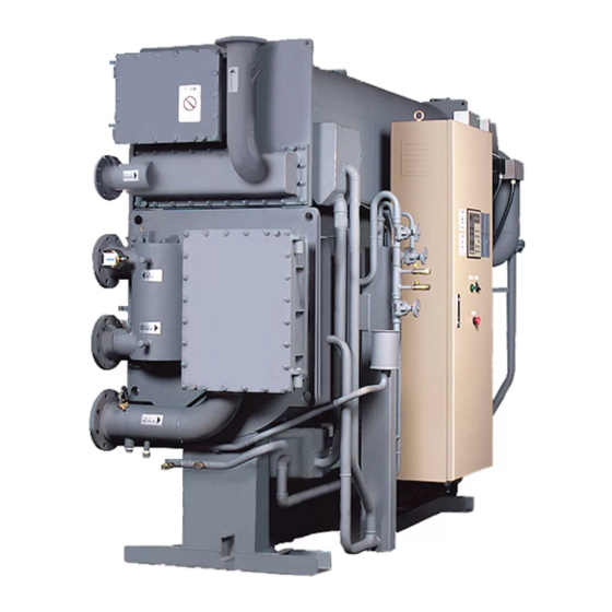
Page 13: Illustration
3. ILLUSTRATION 3-1. DETAIL OF TYPICAL CHILLER Cooling water inlet Chilled water outlet Chilled water flow switch Chilled water inlet WATER HEADER SIDE Rupture disk Control panel Purge unit Heat exchanger CONTROL PANEL SIDE Note: The positions or quantity of parts differ according to the model and options. - Page 14 Condenser Generator Hot water inlet Hot water outlet Cooling water outlet Evaporator Absorber WATER HEADER SIDE (OPPOSITE) Refrigerant blow valve Purge pump Refrigerant pump Absorbent pump No.2 Absorbent pump No.1 EVAPORATOR SIDE Note: The positions or quantity of parts differ according to the model and options.
-
Page 15: Typical Control Panel
3-2. TYPICAL CONTROL PANEL 3-2-1 UL type Fan, Filter Operation board Terminal block Purge pump on-off switch Purge indication lamp Terminal block Emergency stop button Main circuit breaker Terminal block for power supply Ground terminal !! CAUTION !! Do not push the emergency stop button except in emergency. Otherwise the chiller/heater may be damaged. -
Page 16: Flowchart Of Chiller And Function Of Each Section
3-3. FLOWCHART OF CHILLER AND FUNCTION OF EACH SECTION DT16 Hot water Rupture disk control valve Condenser Cooling water Inlet 69PR DT15 Generator Purge tank Driving hot water B valve 69CH Cooling water Chilled water Outlet Outlet Inlet Absorber Evaporator Absorbent pump No.2 Purge DT10... - Page 17 The List of sensors SYMBOL NAME Chilled water outlet temperature Cooling water outlet temperature Generator temperature Condenser temperature Chilled water inlet temperature Cooling water inlet temperature DT10 Diluted solution temperature at Absorber outlet DT11 Refrigerant temperature at Evaporator DT12 Cooling water mid temperature DT15 Driving hot water inlet temperature DT16...
-
Page 18: Operating Instructions
4. OPERATING INSTRUCTIONS 4-1. TURN ON THE MAIN CIRCUIT BREAKER Self-diagnostic function starts when the breaker inside the control panel of the Chiller is turned on. After completing the self-diagnosis, the data display on the operation board shows the following. (1) Data display (7 segment LED) and all LEDs light up. -
Page 19: Description Of Keys And Their Functions
4-2. DESCRIPTION OF KEYS AND THEIR FUNCTIONS 1. Operation indication lamp :Operation indication lamps light while the chiller, pumps, etc. operate. 2. Stop indication lamp :Stop indication lamps light while the chiller, pumps, etc. stop. 3. Alarm indication lamp :Alarm indication lamps light up when an abnormality occurred. 4. -
Page 20: Operation
4-3. OPERATION 4-3-1. Pre-operation check Check the following items before starting operation. (1) Check of the setting point of the chilled water outlet temperature Make sure that the chilled water outlet temperature is set as specified. As for the indication of set value, please refer to Section 4-5. (2) Check of the hot water line a) Make a daily inspection.(Refer to Section 5.) b) Check that the valve(s) is open. - Page 21 4-3-2. Start a operation (1) Local operation mode a) Confirm the "LOCAL" indication lamp of the key lights. b) Keep pressing “RUN” key for more than a second and make sure that “RUN” indicator lamp of the key lights. c)Automatic operation starts. Local key Run key (2) Remote operation mode...
- Page 22 4-3-3. Stop a operation (1) Local operation mode a) Keep pressing "STOP" key on the operation board for more than a second. b) Make sure that “RUN” indication lamp goes off and "STOP" indication lamp lights. Stop key (2) Remote operation mode a) Turn on the stop switch on the remote control panel of field supply.
-
Page 23: How To Change The Indication On Data Display
4-4. HOW TO CHANGE THE INDICATION ON DATA DISPLAY 4-4-1. Regular indication Data display on the operation board usually shows genarator temperature as follows. (Display Example) Data display It returns to the genarator temperature indication when there is no key operation for 1 minute. 4-4-2. - Page 24 4-4-3. Typical indication flow Data can be displayed in real time. Operation time, on-off times, temperature, set value, alarm informations etc are displayed. Each data is identified by the data code. You can scroll the data code by ▲▼ key. It shows an alarm code only when an abnormality occur and when multiple abnormality occurrs the highest-priority one is displyed and a dot is shown at the bottom right of the alam code.
-
Page 25: How To Change The Indication And The Setting Point
4-5. HOW TO CHANGE THE INDICATION AND THE SETTING POINT 4-5-1. Indication of setting The present "chilled water temperature setting", or "Hot water temperature setting" can be checked by following Section 4-4-2. How to change the indication. 4-5-2. How to change setting After showing present setting, it can be changed in the following process. -
Page 26: Maintenance Message
4-6. MAINTENANCE MESSAGE 4-6-1. Function When a trouble which could disturb an efficient operation of the Chiller is predicted, it shows a notice. 4-6-2. How it is shown Data code is indicated on the data display as follows. Maintenance message Data name Data code ★... -
Page 27: Alarm Indications And Actions To Be Taken
4-7. ALARM INDICATIONS AND ACTIONS TO BE TAKEN 4-7-1. How they are shown When an abnormity is detected, alarm buzzer sounds(option) and the alarm code is shown on the data display and the indication lamp of “STOP” key blinks. The Chiller stops for safety reasons after a dilution cycle operation. Depending on the kind of the alarm, it stops without a dilution cycle operation. - Page 28 4-7-3. Content of alarm and setting List of alarm and setting Purpose Display Contents of alarm Set point Chilled water Chilled water temperature is too low. C(36.5 F) or below freeze protection Chilled water pump interlock failure Few flow rate of chilled water 50% or below ...
- Page 29 4-7-4. Locating Alarm and Disposal List of Alarm Indications with their Causes and Remedies in cooling mode Display alarm Set point Recovery point Action Contact a service agent. Check J-01 Chilled water low temp. C or below above 2.5 other alarm with ▲key (36.5 (36.5 Operate the chilled water pump...
-
Page 30: Maintenance
5. MAINTENANCE 5-1. DAILY INSPECTION If you find an abnormal condition, contact a service agent. (1) Abnormal noise of absorbent pump and refrigerant pump. Consult the plant management company for the following items. (2) Cleaning of the cooling tower and the strainer of the cooling water line. (3) Check of the cooling tower condition. - Page 31 Purge tank Upper shell Purge indication lamp (green) B valve Lower shell Purge pump on-off switch Purge pump Purge unit 1) Open the gas ballast valve slightly until you can hear the exhaust sound. If you open it fully, purge pump oil will become dirty easily. 5-2-2.
-
Page 32: Water Treatment
5-2-3. Refrigerant blow down During a cooling operation, a little quantity of absorbent could mix into the refrigerant. Accumulated amount of the mixed absorbent could increase by a long-term operation and result in lowering of the cooling capacity, therefore refrigerant blow down must be performed at least once in a cooling season. By this work, the contaminated refrigerant is transferred to absorber side, and new, clear refrigerant is replaced. - Page 33 2. Analysis of water quality Check the water quality of make up water to satisfy the water quality guideline “JRA GL-02-1994”. About the analysis of water quality, contact a water treatment company. 3. Method of water treatment (1) Blow down Manage the recycling water quality to satisfy the water quality guideline “JRA GL-02-1994”.
- Page 34 Water quality standard for chilled water Chilled water line Tendency Circulation Make up Corrosion Scale T=<20C(68F) pH(at 25C(77F)) 6.5 - 8.0 6.0 - 8.0 Electrical conductivity 25C ms/m 40 or less 30 or less Chloride ion 50 or less 50 or less mgCl Sulfuric acid ion 50 or less...
- Page 35 6. Typical water treatment Even if make-up water for cooling water meets the water standards, the water quality gets worse by its concentration, therefore the following water treatment is necessary. To varying degrees, chilled water also requires this treatment. In case of an application of concrete heat storage tank, special attention should be paid to water treatment.
-
Page 36: Recommended Schedule For Maintenance And Replacement Of Main Components
4. Discharge the water from the discharge port on the cooling water inlet. 5. Keep the discharge port open during shut down. (2) Chilled water Keep the evaporator full with the water. (Wet lay up) (3) Hot water Keep the generator full with the water. (Wet lay up) 5-3-3. -
Page 37: Maintenance Contract
6. MAINTENANCE CONTRACT 6-1. ANNUAL MAINTENANCE CONTRACT Periodic inspection and parts replacement is important for safety operation. The inspection work requires a special skill. Please contract our service agent for details. We are not responsible for any troubles that are caused by maintenance service performed by a non-specialist. - Page 38 Manufacturer CARRIER SCS Route de Thil - BP49 01122 MONTLUEL CEDEX, FRANCE...
Need help?
Do you have a question about the 16LJ-A Series and is the answer not in the manual?
Questions and answers