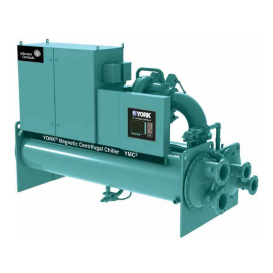
York YMC 2 Manual
Centrifugal liquid chillers
Hide thumbs
Also See for YMC 2:
- Operation and maintenance (146 pages) ,
- Installation and assembly manual (74 pages) ,
- Manual (71 pages)

Subscribe to Our Youtube Channel
Related Manuals for York YMC 2


Summary of Contents for York YMC 2
- Page 1 Centrifugal Liquid Chillers Installation Guide Supersedes: 160.78-N1 (512) Form 160.78-N1 (222) Model A with OptiView™ Control Center R-134a Issue Date: February 2, 2022...
- Page 2 Form 160.78-N1 Issue date: 2/02/2022 Important Read before proceeding General safety guidelines This equipment is a relatively complicated apparatus. which it is situated, as well as severe personal injury or During installation, operation maintenance or service, death to themselves and people at the site. individuals may be exposed to certain components or This document is intended for use by owner-authorized conditions including, but not limited to: refrigerants,...
- Page 3 Form 160.78-N1 Issue date: 2/02/2022 Changeability of this document In complying with Johnson Controls’ policy for con- Operating/service personnel maintain responsibility for tinuous product improvement, the information con- the applicability of these documents to the equipment. tained in this document is subject to change without If there is any question regarding the applicability of notice.
- Page 4 Form 160.78-N1 Issue date: 2/02/2022 System nomenclature Y M C 2 - S 0756 A A YORK Mod level Magnetic bearing Refrigerant R-134a Centrifugal chiller Capacity in kW S = Single stage T = Two stage Compressor nomenclature M1 B - 197 F A A...
-
Page 5: Table Of Contents
Form 160.78-N1 Issue date: 2/02/2022 Table of contents Section 1 - Shipping ..............................7 General ................................7 Component combinations ..........................7 Field assembled units only ..........................8 shipment forms ............................8 Form 1 ..............................8 Form 2 ..............................9 Form 3 ..............................9 Form 7 ..............................10 Form 9 ..............................10 Form 10 .............................. - Page 6 Form 160.78-N1 Issue date: 2/02/2022 List of figures Figure 1 - YMC chiller components ......................... 7 Figure 2 - Rigging ..............................13 Figure 3 - Neoprene isolators ..........................15 Figure 4 - Neoprene isolators ..........................16 Figure 5 - Spring isolators ............................17 Figure 6 - Spring isolators............................18 Figure 7 - Typical refrigerant vent piping ........................19 Figure 8 - Schematic of a typical piping arrangement ....................20 Figure 9 - FAA unit insulation ..........................22...
-
Page 7: Section 1 - Shipping
Form 160.78-N1 Issue date: 2/02/2022 Section 1 - Shipping General Component combinations This manual provides instructions for rigging and in- Figure 1 identifies the major components of the YMC stalling a YMC Liquid Chilling Unit. Chiller. The chiller is customized based on the selected combination of motor, compressor, evaporator, and Chillers can be shipped as a single factory assembled, condenser. -
Page 8: Field Assembled Units Only
Form 160.78-N1 Section 1 - Shipping Issue date: 2/02/2022 Field assembled units only • Form 10 (shipped in two assemblies) • Form 11 (shipped in two assemblies) If the chiller is not shipped complete as shown in Form 1 or 2 below, use the YMC Unit Reassembly Manual (Form 160.78-N2) in conjunction with this installation Units that are shipped dismantled MUST... - Page 9 Form 160.78-N1 Section 1 - Shipping Issue date: 2/02/2022 • Variable speed drive inhibitor Refrigerant charges are shipped separately. • Other shipped loose items, including piping, wa- Arrangements with the local service office ter temperature controls, wiring, etc. must be made to ensure refrigerant is on- site when the unit is ready to be charged.
- Page 10 Form 160.78-N1 Section 1 - Shipping Issue date: 2/02/2022 • Other shipped loose items, including piping, wa- • All openings the shells are closed and charged ter temperature controls, and wiring with a 2 psig to 3 psig (14 kPa to 20 kPa) holding charge of dry nitrogen.
- Page 11 Form 160.78-N1 Section 1 - Shipping Issue date: 2/02/2022 • Interconnecting piping is assembled and the com- • The complete unit is factory leak-tested, evacuat- plete unit is factory leak-tested then evacuated ed, and shipped charged with R-134a refrigerant. and shipped charged with a 2 psig to 3 psig (14 •...
-
Page 12: Inspection, Damage, And Shortage
Form 160.78-N1 Section 1 - Shipping Issue date: 2/02/2022 Inspection, damage, and shortage Condenser-side assembly (condenser, OptiView™ control center, and variable speed Check the unit shipment on arrival to see that all major drive) pieces, boxes and crates are received. Check each unit The condenser-side assembly consists of the condens- on the trailer or rail car when received, before unload- er, the OptiView™... -
Page 13: Section 2 - Installation
Form 160.78-N1 Issue date: 2/02/2022 Section 2 - Installation Overview Rig chiller unit The installation process consists of the following steps: The complete standard chiller is shipped without skids. When optional skids are used it may be necessary to 1. Rig chiller unit remove the skids so riggers skates can be used under the unit end sheets to reduce overall height. -
Page 14: Determine Location
Form 160.78-N1 Section 2 - Installation Issue date: 2/02/2022 The rigging, operating weights, and over- Rig unit to final location all dimensions are provided in Section Rig the unit to its final location on the floor or mount- 3 - Dimensions, nozzle arrangements, ing pad, lift the unit (or shell assembly) by means of an and weights to help you determine the overhead lift and lower the unit to its mounting posi-... -
Page 15: Figure 3 - Neoprene Isolators
Form 160.78-N1 Section 2 - Installation Issue date: 2/02/2022 LD12638 LD12639 Unit weight up to 5,500 lb (2,494 kg) Unit weight 5,501 lb to 8,000 lb (2,495 kg to 3,628 kg) LD12641 LD12640 Unit weight 8,001 lb to 15,000 lb (3,629 kg to 6,804 kg) Unit weight 15,001 lb to 29,000 lb (6,805 kg to 13,154 kg) Note: Dimensions are shown in in. -
Page 16: Figure 4 - Neoprene Isolators
Form 160.78-N1 Section 2 - Installation Issue date: 2/02/2022 LD12642 Operating unit weight Dimension A Dimension B Dimension C Dimension D Dimension E 15,001 lb to 29,000 lb 62 in. (1575) 31 in. (787) 31 in. (787) 10 in. (254) 8 in. -
Page 17: Install Optional Spring Isolators
Form 160.78-N1 Section 2 - Installation Issue date: 2/02/2022 Install optional spring isolators Level the unit The longitudinal alignment of the unit should be Bolt isolators to the unit checked by placing a level on the top center of the If ordered, spring type isolator assemblies are fur- evaporator shell under the compressor/motor assem- nished with the unit. -
Page 18: Figure 6 - Spring Isolators
Form 160.78-N1 Section 2 - Installation Issue date: 2/02/2022 LD12643 Operating unit weight Dimension A Dimension B Dimension C Dimension D Dimension E Dimension F 6 7/8 in. 5 1/2 in. Up to 35,000 lb (15,880 kg) 62 in. (1575) 31 in. -
Page 19: Make Connections
Form 160.78-N1 Section 2 - Installation Issue date: 2/02/2022 Make connections Piping connections After the unit is leveled (and wedged in place for op- After the unit is leveled, place wedges and/or shims un- tional spring isolators) the piping connections may be der each corner to solidly support the unit in this position made;... -
Page 20: Figure 8 - Schematic Of A Typical Piping Arrangement
Form 160.78-N1 Section 2 - Installation Issue date: 2/02/2022 LD08529 Figure 8 - Schematic of a typical piping arrangement ter circuits to protect the chiller and other components Evaporator and condenser water piping including the pumps, tower spray nozzles, chilled water The evaporator and condenser liquid heads of chiller coils and controls. -
Page 21: Refrigerant Relief Piping
Form 160.78-N1 Section 2 - Installation Issue date: 2/02/2022 than the required minimum. Refer to the YMC vent line should be sized in accordance with the ANSI/ Engineer- ing Guide (Form 160.78-EG1) for required minimum ASHRAE-15, or local code. The vent line must include Condenser and Evaporator temperatures. -
Page 22: Figure 9 - Faa Unit Insulation
Form 160.78-N1 Section 2 - Installation Issue date: 2/02/2022 HOT GAS LIQUID LINE LINE SIGHT GLASS CONDENSER EVAPORATOR CONDENSER EVAPORATOR Tape Insulation around flanges to allow for removal. HOT GAS CONNECTION SIGHT GLASS LD03827a Bold lines and shaded components represent insulation. Figure 9 - FAA unit insulation JOHNSON CONTROLS... -
Page 23: Figure 10 - Fab Unit Insulation
Form 160.78-N1 Section 2 - Installation Issue date: 2/02/2022 HOT GAS LIQUID LINE LINE SIGHT GLASS CONDENSER EVAPORATOR CONDENSER EVAPORATOR Tape Insulation around flanges to allow for removal. HOT GAS CONNECTION INSULATE LINE LD03827b Bold lines and shaded components represent insulation. Figure 10 - FAB unit insulation JOHNSON CONTROLS... -
Page 24: Apply Insulation
Form 160.78-N1 Section 2 - Installation Issue date: 2/02/2022 Apply insulation Units are furnished factory anti-sweat insulated on or- der at additional cost. This includes all low tempera- Do not field insulate until the unit has ture surfaces except the two cooler liquid heads. been leak tested under the supervision of the Johnson Controls representative. -
Page 25: Section 3 - Dimensions, Nozzle Arrangements, And Weights
Form 160.78-N1 Issue date: 2/02/2022 Section 3 - Dimensions, nozzle arrangements, and weights Compressor unit dimensions Additional operating height clearance to floor Ft - in. (mm) Type of chiller mounting Neoprene pad isolators 1 3/4 in. (45) Spring isolators 1 in. deflection 1 in. -
Page 26: Evaporator Nozzle Arrangements (150 Psi Compact Waterboxes)
Form 160.78-N1 Section 3 - Dimensions, nozzle arrangements, and weights Issue date: 2/02/2022 Evaporator nozzle arrangements (150 psi compact waterboxes) 1-pass evaporator nozzle arrangements Left end Right end Right end Left end LD14004 Figure 12 - Evaporators - compact waterboxes (1-pass nozzle arrangements) 2-pass evaporator nozzle arrangements Lower right end Upper right end... -
Page 27: Figure 15 - Evaporators - 150 Psi Compact Waterboxes
Form 160.78-N1 Section 3 - Dimensions, nozzle arrangements, and weights Issue date: 2/02/2022 Evaporator nozzle arrangements (150 psi compact waterboxes) LD14020 Dimensions, ft - in. (mm) Evaporator shell code EA25 1 ft 2 1/8 in. (359) 0 ft 6 5/16 in. (160) NOTES: 1. -
Page 28: Condenser Nozzle Arrangements (150 Psi Compact Waterboxes)
Form 160.78-N1 Section 3 - Dimensions, nozzle arrangements, and weights Issue date: 2/02/2022 Condenser nozzle arrangements (150 psi compact waterboxes) 1-pass condenser nozzle arrangements Left end Right end Right end Left end LD14008 Figure 16 - Condensers - compact waterboxes (1-pass nozzle arrangements) 2-pass condenser nozzle arrangements Lower right end Upper right end... -
Page 29: Figure 19 - Condensers - 150 Psi Compact Waterboxes
Form 160.78-N1 Section 3 - Dimensions, nozzle arrangements, and weights Issue date: 2/02/2022 Condenser nozzle arrangements (150 psi compact waterboxes) LD14020 Dimensions, ft - in. (mm) Condenser shell code CA21 1 ft 1 3/4 in. (349) 0 ft 5 13/16 in. (148) CA25 1 ft 1 3/4 in. -
Page 30: Evaporator Nozzle Arrangements (150 Psi Marine Waterboxes)
Form 160.78-N1 Section 3 - Dimensions, nozzle arrangements, and weights Issue date: 2/02/2022 Evaporator nozzle arrangements (150 psi marine waterboxes) 1-pass evaporator nozzle arrangements Left end Right end Right end Left end LD14012 Figure 20 - Evaporators - marine waterboxes (1-pass nozzle arrangements) 2-pass evaporator nozzle arrangements Lower right end Upper right end... -
Page 31: Figure 23 - Evaporators - 150 Psi Marine Waterboxes
Form 160.78-N1 Section 3 - Dimensions, nozzle arrangements, and weights Issue date: 2/02/2022 Evaporator nozzle arrangements (150 psi marine water boxes) LD14021 1-pass 2-pass 3-pass Evaporator shell code 1 ft 6 5/8 in. 0 ft 8 11/16 in. 1 ft 4 1/2 in. 0 ft 7 5/8 in. -
Page 32: Condenser Nozzle Arrangements (150 Psi Marine Waterboxes)
Form 160.78-N1 Section 3 - Dimensions, nozzle arrangements, and weights Issue date: 2/02/2022 Condenser nozzle arrangements (150 psi marine waterboxes) 1-pass condenser nozzle arrangements Left end Right end Right end Left end LD14016 Figure 24 - Condensers - marine waterboxes (1-pass nozzle arrangements) 2-pass condenser nozzle arrangements Lower right end Upper right end... -
Page 33: Figure 27 - Condensers - 150 Psi Marine Waterboxes
Form 160.78-N1 Section 3 - Dimensions, nozzle arrangements, and weights Issue date: 2/02/2022 Condenser nozzle arrangements (150 psi marine waterboxes) LD14021 1-pass 2-pass 3-pass Condenser shell code 1 ft 8 9/16 in. 0 ft 9 3/4 in. 1 ft 4 7/16 in. 0 ft 7 11/16 in. -
Page 34: Weights
Form 160.78-N1 Section 3 - Dimensions, nozzle arrangements, and weights Issue date: 2/02/2022 Weights 150 psi compact and marine waterboxes, lb (kg) Table 2 - Approximate unit weight* (max tube count using 150 psi compact waterboxes) Shipping weight, Operating weight, Est. -
Page 35: Table 5 - Si Metric Conversion
Form 160.78-N1 Issue date: 2/02/2022 The following factors can be used to convert from English to the most common SI Metric values. Table 5 - SI metric conversion Measurement Multiply English unit By factor To obtain metric unit Capacity Tons refrigerant effect (ton) 3.516 Kilowatts (kW) Power... - Page 36 5000 Renaissance Drive, New Freedom, Pennsylvania USA 17349 1-800-524-1330 Subject to change without notice. Printed in USA Copyright © by Johnson Controls 2022 www.johnsoncontrols.com ALL RIGHTS RESERVED Form 160.78-N1 (222) Issue Date: February 2, 2022 Supersedes: 160.78-N1 (512)
Need help?
Do you have a question about the YMC 2 and is the answer not in the manual?
Questions and answers