York YMC2 Manual
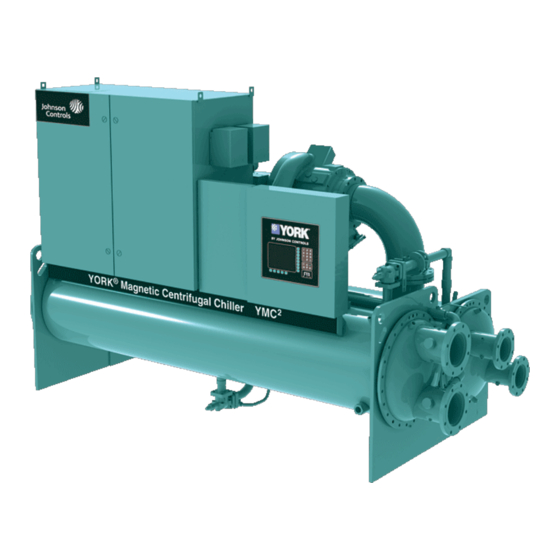
Magnetic bearing centrifugal liquid chillers.
165-1000 tons
580-3520 kw
50 & 60 hz
hfc-134a
or hfc-513a
Hide thumbs
Also See for YMC2:
- Operation and maintenance (146 pages) ,
- Installation and assembly manual (74 pages) ,
- Wiring (56 pages)

Related Manuals for York YMC2


Summary of Contents for York YMC2
- Page 1 FORM 160.84-EG1 (617) MODEL YMC MAGNETIC BEARING CENTRIFUGAL LIQUID CHILLERS 165-1000 Tons 580-3520 kW 50 & 60 Hz HFC-134a or HFC-513A...
- Page 2 FORM 160.84-EG1 (617) Nomenclature SYSTEM NOMENCLATURE Y M C 2 - S 0756 A B YORK Mod Level A = Refrigerant R-134a Magnetic Bearing B = Refrigerant R-513A Centrifugal Chiller Capacity in KW S = Single Stage T = Two Stage...
-
Page 3: Table Of Contents
FORM 160.84-EG1 (617) Table Of Contents INTRODUCTION ..............................5 RATINGS .................................. 8 UNIT COMPONENTS ............................10 EQUIPMENT OVERVIEW ............................12 OPTIVIEW CONTROL CENTER ........................... 17 OPTISPEED VARIABLE-SPEED DRIVE ......................24 ACCESSORIES AND MODIFICATIONS ....................... 26 APPLICATION DATA ............................. 27 UNIT DIMENSIONS ............................... 38 WEIGHTS ................................ - Page 4 FORM 160.84-EG1 (617) THIS PAGE INTENTIONALLY LEFT BLANK. JOHNSON CONTROLS...
-
Page 5: Introduction
The largest unit has only a 14’ (4.3m) heat exchanger length. The YORK OptiView™ Control Center, furnished as standard on each chiller, provides the ultimate in efficiency, monitoring, data recording, chiller protection and operating ease. - Page 6 OIL FREE, with no oil management system required. OPTISOUND™ CONTROL YMC² chillers are equipped with the YORK OptiSound Control as standard. OptiSound Control is a patented combination of centrifugal-chiller hardware and software that re- The OptiSound Control...
- Page 7 Introduction (Cont'd) RELIABILITY Designed for the most reliable chillers we have ever made, the YMC² YORK Magnetic Bearing Compressor will achieve a much better performance because it is based on a successful line of efficient YORK single-stage compressors. With fewer moving parts and straightforward design, YORK single-stage compressors have proven durability in numer- ous applications, especially applications where minimal downtime is a critical concern.
-
Page 8: Ratings
Ratings AHRI CERTIFICATION PROGRAM YORK YK chillers have been tested and certified by Air-Conditioning, Heating and Refrigeration Institute (AHRI) in accordance with the latest edition of AHRI Standard 550/590 (I-P). Under this Certification Program, chillers are regularly tested in strict compliance with this Standard. - Page 9 FORM 160.84-EG1 (617) Ratings (Cont'd) The chiller is engineered for maximum efficiency at both design and part-load operation by taking advantage of the colder cooling tower water temperatures which naturally occur during the winter months. Appreciable power savings are realized from these reduced heads. The minimum entering condenser water temperature for other full and part-load conditions is provided by the following equation: where:...
-
Page 10: Unit Components
FORM 160.84-EG1 (617) Unit Components LD18605 COMPONENT DESCRIPTION OptiView Control Panel Keypad Suction Hot Gas Bypass (Optional) Refrigerant Relief Valves Endsheet Condenser Sight Glass Lockout Handle JOHNSON CONTROLS... - Page 11 FORM 160.84-EG1 (617) Unit Components (Cont'd) LD18606 COMPONENT DESCRIPTION VSD Coolant Reservoir Nozzles Compact Waterbox Power Panel Evaporator Suction Direct Dive Compressor Motor with Active Magnetic Bearings JOHNSON CONTROLS...
-
Page 12: Equipment Overview
FORM 160.84-EG1 (617) Equipment Overview YORK YMC² Centrifugal Liquid Chillers are completely factory-packaged including the evaporator, condenser, compressor, motor, VSD, control center, and all interconnecting unit piping and wiring. The initial charge of refrigerant is supplied for each chiller. Actual shipping procedures for the chiller will depend on a number of project-specific details. - Page 13 Equipment Overview (Cont'd) OPTISOUND CONTROL YMC² chillers are equipped with the YORK OptiSound Control as standard. The YORK OptiSound Control is a patented combination of centrifugal-chiller hardware and software that reduces operational sound levels, expands the chiller operating range, and improves chiller performance.
- Page 14 316 stainless steel, which is suited to very high working pressures. REFRIGERANT FLOW CONTROL Refrigerant flow to the evaporator is controlled by the YORK variable orifice control sys- tem. Liquid refrigerant level is continuously monitored to provide optimum subcooler, condenser and evaporator performance. The variable orifice electronically adjusts to all Real-World operating conditions, providing the most efficient and reliable operation of refrigerant flow control.
- Page 15 FORM 160.84-EG1 (617) Equipment Overview (Cont'd) CODES AND STANDARDS • ASME Boiler and Pressure Vessel Code – Section Vlll Division 1. • AHRI Standard 550/590 • c/U.L. – Underwriters Laboratory • ASHRAE 15 – Safety Code for Mechanical Refrigeration • ASHRAE Guideline 3 – Reducing Emission of Halogenated Refrigerants in Refrig- eration and Air-Conditioning Equipment and Systems • N.E.C.
- Page 16 FORM 160.84-EG1 (617) Equipment Overview (Cont'd) The unit is first factory assembled, refrigerant piped, wired and leak tested; then disman- tled for shipment. Close-coupled compressor/hermetic motor assembly removed from shells and skidded. Evaporator/condenser is not skidded. FORM 7 – Driveline Separate from Split Shells Shipped as four major assemblies: • Driveline (motor/compressor assembly) • Evaporator...
-
Page 17: Optiview Control Center
NOTE: Please refer to the OptiView Control Center Operator's Manual for a complete description of features and functionality. The YORK OptiView Control Center is a factory mounted, wired and tested microproces- sor based control system for HFC-134a centrifugal chillers. For the YMC², it controls the leaving chilled liquid temperature and limits the motor current via control of the Variable Geometry Diffuser (VGD) and Variable Speed Drive (VSD). - Page 18 FORM 160.84-EG1 (617) OptiView Control Center (Cont'd) also as a team. This new protocol allows increased remote control of the chiller, as well as 24-hour performance monitoring via a remote site. In addition, compatibility is maintained with the present network of BAS communications. The chiller also maintains the standard digital remote capabilities as well.
- Page 19 FORM 160.84-EG1 (617) OptiView Control Center (Cont'd) EVAPORATOR SCREEN This screen displays a cutaway view of the chiller evaporator. All setpoints relating to the evaporator side of the chiller are maintained on this screen. Animation of the evaporation process indicates whether the chiller is presently in a RUN condition (bubbling) and liquid flow in the pipes is indicated by alternating shades of color moving in and out of the pipes.
- Page 20 FORM 160.84-EG1 (617) OptiView Control Center (Cont'd) COMPRESSOR SCREEN This screen displays a cutaway view of the chiller compressor, revealing the impeller, and shows all conditions associated with the compressor. Animation of the compressor impel- ler indicates whether the chiller is presently in a RUN condition. This screen also serves as a gateway to subscreens for the Magnetic Bearing Controller (MBC), the Variable Ge- ometry Diffuser (VGD), and the Power Panel.
- Page 21 FORM 160.84-EG1 (617) OptiView Control Center (Cont'd) VARIABLE GEOMETRY DIFFUSER This can be accessed from the COMPRESSOR screen and gives the basic stall, position, and pressure details. LD18613 CAPACITY CONTROL This screen displays all of the data and settings relating to top level capacity control. From this screen you can view readings and setpoints relating to temperature control, override limits, anti-surge control, and status of the capacity control devices.
- Page 22 FORM 160.84-EG1 (617) OptiView Control Center (Cont'd) VARIABLE SPEED DRIVE (VSD) This screen displays a view of the VSD and includes a programmable pulldown demand to automatically limit VSD input loading for minimizing building demand charges. Pulldown time period control over four hours, and verification of time remaining in pulldown cycle from display readout.
- Page 23 FORM 160.84-EG1 (617) OptiView Control Center (Cont'd) HISTORY This screen allows the user to browse through the last ten faults; either safety or cycling shutdowns with the conditions while the chiller is running or stopped. The faults are color coded for ease in determining the severity at a glance, recording the date, time and de- scription.
-
Page 24: Optispeed Variable-Speed Drive
FORM 160.84-EG1 (617) OptiSpeed Variable-Speed Drive The new YORK OptiSpeed VSD is a liquid-cooled, insulated-gate, bipolar-transistor- based (IGBT), pulse-width-modulated (PWM) rectifier/inverter in a highly integrated pack- age. This package is small enough to mount directly onto the chiller. The power section of... - Page 25 FORM 160.84-EG1 (617) OptiSpeed Variable-Speed Drive (Cont'd) The OptiSpeed output sine filter network is composed of inductors and capacitors. The job of the output filter network is to eliminate voltage harmonics from the inverter’s output, and provide a high-quality, almost-sinusoidal voltage to the motor. This completely eliminates all issues related to premature motor insulation failures due to high voltage peaks gen- erated by the inverter, and it additionally allows the motor to run cooler, thus increasing system reliability.
-
Page 26: Accessories And Modifications
FORM 160.84-EG1 (617) Accessories and Modifications ITEM DESCRIPTION STANDARD OPTIONAL Single point Disconnect Switch or Incoming power Connection circuit breaker 50 Hz: 380V, 400V, 415V Incoming Customer Wiring 60 Hz: 460 Volts 60 Hz: 380V, 440V, 480V, Sediment VSD Cooling Hx Protection (For Condenser Fluid Lines) None Accumulator Tube Wall Thickness... -
Page 27: Application Data
FORM 160.84-EG1 (617) Application Data The following discussion is a user’s guide in the application and installation of YMC² chill- ers to ensure the reliable, trouble-free life for which this equipment was designed. While this guide is directed towards normal, water-chilling applications, a Johnson Controls sales engineer can provide complete recommendations on other types of applications. - Page 28 FORM 160.84-EG1 (617) Application Data (Cont'd) The chillers can tolerate a 50% flow rate change in one minute that is typically associ- ated with the staging on or off of an additional chiller; however a lower flow rate change is normally used for better system stability and set point control.
- Page 29 FORM 160.84-EG1 (617) Application Data (Cont'd) Condenser Water – The chiller is engineered for maximum efficiency at both design and part-load operation by taking advantage of the colder cooling tower water temperatures which naturally occur during the winter months. Appreciable power savings are realized from these reduced heads.
- Page 30 FORM 160.84-EG1 (617) Application Data (Cont'd) Series/Parallel Arrangement – Chillers may be applied in pairs with chilled water circuits connected in series and condenser water circuits connected in parallel. All of the chilled water flows through both evaporators with each unit handling approximately one-half of the total load.
- Page 31 FORM 160.84-EG1 (617) Application Data (Cont'd) REFRIGERANT RELIEF PIPING Each chiller is equipped with a dual pressure relief valve on the condenser and either a dual relief valve on the evaporator, or a single relief valve on the evaporator if the optional refrigerant isolation valves are ordered.
- Page 32 FORM 160.84-EG1 (617) Application Data (Cont'd) ELECTRICAL CONSIDERATIONS Unit input conductor size must be in accordance with the National Electrical Code (N.E.C.), or other applicable codes, for the unit full load amperes (FLA). Please refer to the sub- mittal drawings for the FLA and Minimum Current Ampacity (MCA) specific to each ap- plication.
- Page 33 FORM 160.84-EG1 (617) Application Data (Cont'd) TABLE 2 - WATER FLOW RATE LIMITS IN GPM (L/S) – BASED UPON STANDARD TUBES @ DESIGN FULL LOAD CONDITIONS EVAPORATOR CONDENSER EVAPORATOR CONDENSER 1 PASS 2 PASS 3 PASS 1 PASS 2 PASS 3 PASS MODEL MODEL...
- Page 34 FORM 160.84-EG1 (617) Application Data (Cont'd) TABLE 2 - WATER FLOW RATE LIMITS IN GPM (L/S) – BASED UPON STANDARD TUBES @ DESIGN FULL LOAD CONDITIONS (CONT'D) EVAPORATOR CONDENSER EVAPORATOR CONDENSER 1 PASS 2 PASS 3 PASS 1 PASS 2 PASS 3 PASS MODEL MODEL...
- Page 35 FORM 160.84-EG1 (617) Application Data (Cont'd) TABLE 2 - WATER FLOW RATE LIMITS IN GPM (L/S) – BASED UPON STANDARD TUBES @ DESIGN FULL LOAD CONDITIONS (CONT'D) EVAPORATOR CONDENSER EVAPORATOR CONDENSER 1 PASS 2 PASS 3 PASS 1 PASS 2 PASS 3 PASS MODEL MODEL...
- Page 36 FORM 160.84-EG1 (617) Application Data (Cont'd) TABLE 2 - WATER FLOW RATE LIMITS IN GPM (L/S) – BASED UPON STANDARD TUBES @ DESIGN FULL LOAD CONDITIONS (CONT'D) EVAPORATOR CONDENSER EVAPORATOR CONDENSER 1 PASS 2 PASS 3 PASS 1 PASS 2 PASS 3 PASS MODEL MODEL...
- Page 37 FORM 160.84-EG1 (617) Application Data (Cont'd) TABLE 2 - WATER FLOW RATE LIMITS IN GPM (L/S) – BASED UPON STANDARD TUBES @ DESIGN FULL LOAD CONDITIONS (CONT'D) EVAPORATOR CONDENSER EVAPORATOR CONDENSER 1 PASS 2 PASS 3 PASS 1 PASS 2 PASS 3 PASS MODEL MODEL...
-
Page 38: Unit Dimensions
FORM 160.84-EG1 (617) Unit Dimensions 1. The following notes apply to the dimension drawings on pages 41 through 67. 2. All dimensions are approximate. Certified dimensions are available on request. 3. The standard water nozzles are Schedule 40 pipe size, furnished as welding stub- outs with ANSI/AWWA C-606 grooves, allowing the option of welding, flanges, or use of ANSI/AWWA C-606 couplings. Factory-installed, class 150 (ANSI B16.5, round slip-on forged carbon steel with 1/16" raised face), water flanged nozzles are optional (add 1/2" to nozzle length). Companion flanges, nuts, bolts, and gaskets are not furnished. - Page 39 FORM 160.84-EG1 (617) Unit Dimensions (Cont'd) M1 MOTOR LD18621 ADDITIONAL OPERATING HEIGHT CLEARANCE TO FLOOR - IN (MM) TYPE OF CHILLER MOUNTING 1 3/4" NEOPRENE PAD ISOLATORS (45) 1" SPRING ISOLATORS 1" DEFLECTION (25) 3/4" DIRECT MOUNT (19) M1 MOTOR DIMENSIONS FT-IN (MM) EVAPORATOR CONDENSER CODE...
- Page 40 FORM 160.84-EG1 (617) Unit Dimensions (Cont'd) M2 MOTOR LD18627 ADDITIONAL OPERATING HEIGHT CLEARANCE TO FLOOR - IN (MM) TYPE OF CHILLER MOUNTING NEOPRENE PAD ISOLATORS 1 3/4" (45) SPRING ISOLATORS 1" DEFLECTION 1" (25) DIRECT MOUNT 3/4" (19) M2 MOTOR DIMENSIONS FT - IN (MM) EVAPORATOR CONDENSER CODE...
- Page 41 FORM 160.84-EG1 (617) Unit Dimensions (Cont'd) M6 MOTOR LD18627 ADDITIONAL OPERATING HEIGHT CLEARANCE TO FLOOR - IN (MM) TYPE OF CHILLER MOUNTING NEOPRENE PAD ISOLATORS 1 3/4" (45) SPRING ISOLATORS 1" DEFLECTION 1" (25) DIRECT MOUNT 3/4" (19) M6 MOTOR DIMENSIONS FT - IN (MM) EVAPORATOR CONDENSER CODE...
- Page 42 FORM 160.84-EG1 (617) Unit Dimensions (Cont'd) EVAPORATORS – COMPACT WATER BOXES 1-PASS NOZZLE ARRANGEMENTS EVAPORATOR Left End Right End Right End Left End 2-PASS NOZZLE ARRANGEMENTS EVAPORATOR Lower Right End Upper Right End Lower Left End Upper Left End 3-PASS NOZZLE ARRANGEMENTS EVAPORATOR Right End...
- Page 43 FORM 160.84-EG1 (617) Unit Dimensions (Cont'd) EVAPORATORS – COMPACT WATER BOXES COMPACT WATER BOXES-150 AND 300 PSI NOZZLE PIPE SIZE (IN) EVAPORATOR NOZZLE DIMENSIONS FT-IN (MM) NUMBER EVAPORATOR 1-PASS 2-PASS 3-PASS SHELL CODE OF PASSES 5" 1' 3-1/2" 1' 10" 1' 5"...
- Page 44 FORM 160.84-EG1 (617) Unit Dimensions (Cont'd) CONDENSERS – COMPACT WATER BOXES 1-PASS NOZZLE ARRANGEMENTS CONDENSER Left End Right End Right End Left End 2-PASS NOZZLE ARRANGEMENTS CONDENSER Lower Right End Upper Right End Lower Left End Upper Left End 3-PASS NOZZLE ARRANGEMENTS CONDENSER Right End...
- Page 45 FORM 160.84-EG1 (617) Unit Dimensions (Cont'd) CONDENSERS – COMPACT WATER BOXES COMPACT WATER BOXES-150 AND 300 PSI NOZZLE PIPE SIZE (IN) CONDENSER NOZZLE DIMENSIONS FT-IN (MM) NUMBER CONDENSER 1-PASS 2-PASS 3-PASS SHELL CODE OF PASSES 1' 3-1/2" 1' 11-1/2" 1' 5" 2' 6"...
- Page 46 FORM 160.84-EG1 (617) Unit Dimensions (Cont'd) EVAPORATORS & CONDENSERS – COMPACT WATER BOXES ONE PASS TWO PASS THREE PASS LD18624 JOHNSON CONTROLS...
- Page 47 FORM 160.84-EG1 (617) Unit Dimensions (Cont'd) EVAPORATORS & CONDENSERS – COMPACT WATER BOXES 150 AND 300 PSI COMPACT WATER BOXES DIMENSIONS FT - IN (MM) NOZZLE PIPE "F" NOZZLE - DIAMETER SIZE (IN) EVAP NUMBER SHELL OF PASSES CODE 1' 2-5/8" 1' 2-11/16"...
- Page 48 FORM 160.84-EG1 (617) Unit Dimensions (Cont'd) EVAPORATORS & CONDENSERS – COMPACT WATER BOXES ONE PASS TWO PASS THREE PASS JOHNSON CONTROLS...
- Page 49 FORM 160.84-EG1 (617) Unit Dimensions (Cont'd) EVAPORATORS & CONDENSERS – COMPACT WATER BOXES 150 AND 300 PSI COMPACT WATER BOXES DIMENSIONS FT - IN (MM) NOZZLE PIPE "F" NOZZLE - DIAMETER SIZE (IN) COND NUMBER COMP CODE SHELL OF PASSES CODE M1B-197FAB 1' 2-5/16"...
- Page 50 FORM 160.84-EG1 (617) Unit Dimensions (Cont'd) EVAPORATORS – MARINE WATER BOXES 1-PASS NOZZLE ARRANGEMENTS EVAPORATOR Left End Right End Right End Left End 2-PASS NOZZLE ARRANGEMENTS EVAPORATOR Lower Right End Upper Right End Lower Left End Upper Left End 3-PASS NOZZLE ARRANGEMENTS EVAPORATOR Right End...
- Page 51 FORM 160.84-EG1 (617) Unit Dimensions (Cont'd) EVAPORATORS – MARINE WATER BOXES MARINE WATER BOXES-150 AND 300PSI NOZZLE PIPE EVAPORATOR NOZZLE DIMENSIONS FT - IN (MM) SIZE (IN) EVAPORATOR NUMBER SHELL CODE 1-PASS 2-PASS 3-PASS OF PASSES 11" 11" 1' 3/12" 3' 7"...
- Page 52 FORM 160.84-EG1 (617) Unit Dimensions (Cont'd) CONDENSERS – MARINE WATER BOXES 1-PASS NOZZLE ARRANGEMENTS CONDENSER Left End Right End Right End Left End 2-PASS NOZZLE ARRANGEMENTS CONDENSER Lower Right End Upper Right End Lower Left End Upper Left End 3-PASS NOZZLE ARRANGEMENTS CONDENSER Right End...
- Page 53 FORM 160.84-EG1 (617) Unit Dimensions (Cont'd) CONDENSERS – MARINE WATER BOXES MARINE WATER BOXES-150 AND 300 PSI NOZZLE PIPE CONDENSER NOZZLE DIMENSIONS FT - IN (MM) SIZE (IN) CONDENSER NUMBER SHELL 1-PASS 2-PASS 3-PASS CODE PASSES FLANGE FLANGE 1' 3-1/2" 3' 8-1/2"...
- Page 54 FORM 160.84-EG1 (617) Unit Dimensions (Cont'd) EVAPORATORS – MARINE WATER BOXES LD01342B_1 MARINE WATER BOXES DIMENSIONS FT - IN (MM) 150 AND 300 PSI EVAPORATOR 1-PASS 2-PASS 3-PASS SHELL CODE 1' 7" 8-13/16" 1' 4-7/8" 7-3/4" 6-7/16" 1' 4-7/8" 7-3/4" EA25 (483) (224)
- Page 55 FORM 160.84-EG1 (617) Unit Dimensions (Cont'd) CONDENSERS – MARINE WATER BOXES LD01342B_1 MARINE WATER BOXES DIMENSIONS FT - IN (MM) 150 AND 300 PSI CONDENSER 1-PASS 2-PASS 3-PASS SHELL CODE 9-7/8" 1' 9" 1' 4-7/8" 7-13/16" 5-29/32" 1' 4-7/8" 7-13/16" CA21 (533) (429)
-
Page 56: Weights
FORM 160.84-EG1 (617) Weights M1 MOTOR TABLE 3 - EVAPORATOR WEIGHTS, DRY* 150PSI COMPACT 300PSI COMPACT 150PSI MARINE 300PSI MARINE WATER BOX WEIGHT WATER BOX WEIGHT WATER BOX WEIGHT WATER BOX WEIGHT EVAPORATOR LBS (KG) LBS (KG) LBS (KG) LBS (KG) WEIGHT CODE 1-PASS 2-PASS 3-PASS 1-PASS 2-PASS 3-PASS 1-PASS 2-PASS 3-PASS 1-PASS 2-PASS 3-PASS... - Page 57 FORM 160.84-EG1 (617) Weights (Cont'd) M1 MOTOR TABLE 8 - REFRIGERANT & WATER WEIGHT REFRIGERANT WEIGHT WATER WEIGHT EVAPORATOR CONDENSER LBS (KG)* LBS (KG)** 1106 EA2508 CA2508 (221) (502) CA2110 (249) (437) EA2510 1289 CA2510 (274) (585) 1656 EA2514 CA2514 (387) (751) *Refrigerant weight based on maximum tube bundle.
- Page 58 FORM 160.84-EG1 (617) Weights (Cont'd) M2 MOTOR TABLE 10 - EVAPORATOR WEIGHTS, DRY* 150PSI COMPACT 300PSI COMPACT 150PSI MARINE 300PSI MARINE WATER BOX WEIGHT WATER BOX WEIGHT WATER BOX WEIGHT WATER BOX WEIGHT EVAPORATOR LBS (KG) LBS (KG) LBS (KG) LBS (KG) WEIGHT CODE...
- Page 59 FORM 160.84-EG1 (617) Weights (Cont'd) M2 MOTOR TABLE 12 - VSD WEIGHTS TABLE 14 - UNIT ASSEMBLY – PANELS, PIPING, WIRING, ETC WEIGHT LBS (KG) UNIT ASSEMBLY - 1226 HYP490XH30B-46 PANELS, PIPING, WEIGHT LBS (KG) (556) WIRING, ETC. 1934 HYP612XH30B-46 1254 (886) M2C-218FAC...
- Page 60 FORM 160.84-EG1 (617) Weights (Cont'd) M2 MOTOR TABLE 15 - REFRIGERANT & WATER WEIGHT REFRIGERANT WATER EVAPORATOR CONDENSER WEIGHT LBS (KG)* WEIGHT LBS (KG)** 1510 CB2510 (290) (690) EB2910 1840 CB2910 (390) (840) 1940 CB2514 (410) (880) EB2914 2350 1210 CB2914 (550) (1070)
- Page 61 FORM 160.84-EG1 (617) Weights (Cont'd) M6 MOTOR TABLE 17 - EVAPORATOR WEIGHTS, DRY* 150PSI COMPACT 300PSI COMPACT 150PSI MARINE 300PSI MARINE WATER BOX WEIGHT WATER BOX WEIGHT WATER BOX WEIGHT WATER BOX WEIGHT EVAPORATOR LBS (KG) LBS (KG) LBS (KG) LBS (KG) WEIGHT CODE...
- Page 62 FORM 160.84-EG1 (617) Weights (Cont'd) M6 MOTOR TABLE 19 - VSD WEIGHTS TABLE 21 - UNIT ASSEMBLY – PANELS, PIPING, WIRING, ETC WEIGHT LBS (KG) UNIT ASSEMBLY - 2060 HYP0774XHC30B-46 PANELS, PIPING, WEIGHT LBS (KG) (935) WIRING, ETC. 3806 1300 HYP1278XHC30B-46 M6C-295FAC (1727)
-
Page 63: Guide Specifications
Guide Specifications GENERAL Furnish YORK YMC² Unit(s) as indicated on the drawings. Each unit shall produce a capacity of ____ tons, cooling ____ gpm of _____ from ____ to ____ °F when supplied with ____ gpm of condenser water at ____°F. Power input shall not exceed ____ kW with an IPLV of ____. - Page 64 FORM 160.84-EG1 (617) Guide Specifications (Cont'd) MOTOR The compressor motor shall be a hermetic, oil free, permanent magnet type directly cou- pled to the compressor. The motor will be bolted to a cast iron adapter plate mounted on the compressor to provide factory alignment of the shaft. The motor shaft shall be supported on active magnetic radial and thrust bearings.
- Page 65 FORM 160.84-EG1 (617) Guide Specifications (Cont'd) • KW Meter - The unit’s input power consumption will be measured and displayed digitally via the unit’s control panel. The KW meter accuracy is typically +/- 3% of reading. KW meter scale is 0 - 788 KW. • KWh Meter –...
- Page 66 FORM 160.84-EG1 (617) Guide Specifications (Cont'd) internally and externally enhanced type having plain copper lands at all intermediate tube supports to provide maximum tube wall thickness at the support area. Each tube shall be roller expanded into the tube sheets providing a leak proof seal, and be individually replaceable.
- Page 67 FORM 160.84-EG1 (617) Guide Specifications (Cont'd) STARTUP AND OPERATOR TRAINING The services of a factory trained, field service representative will be provided to supervise the final leak testing, charging and the initial startup and conduct concurrent operator instruction. FACTORY INSULATION Factory-applied, anti-sweat insulation shall be attached to the cooler shell, flow chamber, tube sheets, suction connection, and (as necessary) to the auxiliary tubing.
-
Page 68: Metric (Si) Conversion
FORM 160.84-EG1 (617) Metric (SI) Conversion Values provided in this manual are in the English inch-pound (I-P) system. The following factors can be used to convert from English to the most common Sl Metric values. MULTIPLY THIS TO OBTAIN THIS MEASUREMENT ENGLISH VALUE METRIC VALUE... - Page 69 FORM 160.84-EG1 (617) Notes JOHNSON CONTROLS...
- Page 70 Printed on recycled paper Form 160.84-EG1 (617) Supersedes: 160.84-EG1 (516) © 2016 Johnson Controls, Inc. P.O. Box 423, Milwaukee, WI 53201 Printed in USA www.johnsoncontrols.com Issued on 6/22/2017...
Need help?
Do you have a question about the YMC2 and is the answer not in the manual?
Questions and answers