York YMC2 A Operation And Maintenance
Centrifugal liquid chillers with optiview control center
Hide thumbs
Also See for YMC2 A:
- Operation and maintenance (28 pages) ,
- Connection diagram (18 pages) ,
- Installation manual (78 pages)

Related Manuals for York YMC2 A


Summary of Contents for York YMC2 A
- Page 1 Centrifugal Liquid Chillers Operations and Maintenance Supersedes: 160.78-O1 (820) Form: 160.78-O1 (521) Model A with OptiView™ Control Center 8.1415 R-134a Issue Date: May 19, 2021...
- Page 2 Form 160.78-O1 Issue date: 05/19/2021 Important! Read before proceeding! General safety guidelines This equipment is a relatively complicated apparatus. which it is situated, as well as severe personal injury or During installation, operation maintenance or service, death to themselves and people at the site. individuals may be exposed to certain components or This document is intended for use by owner-authorized conditions including, but not limited to: refrigerants,...
- Page 3 Planned Service Agreement that leverages real time and generalized conditions. In lieu of the traditional and historical data, delivering performance reporting, maintenance program, a Johnson Controls YORK corrective actions required and data enabled guidance Conditioned Based Maintenance (CBM) program can for optimal operation and lifecycle assurance.
- Page 4 Form 160.78-O1 Issue date: 05/19/2021 System nomenclature Y M C 2 - S 0756 A A YORK Mod level Magnetic bearing Refrigerant R-134a Centrifugal chiller Capacity in kW S = Single stage T = Two stage Compressor nomenclature M1 B - 197 F A A...
-
Page 5: Table Of Contents
Form 160.78-O1 Issue date: 05/19/2021 Table of contents SECTION 1 - SYSTEM FUNDAMENTALS ......................7 System components ............................7 Compressor .............................7 Motor ...............................7 Heat exchangers .............................8 Evaporator ...............................8 Condenser ...............................8 Waterboxes .............................8 Refrigerant flow control ...........................8 Optional service isolation valves ......................8 Optional hot gas bypass ..........................8 OptiView Control Center ........................8... - Page 6 Acid cleaning of tubes ...........................22 Testing for evaporator and condenser tube leaks ................. 22 Compressor ..............................23 Electrical controls ............................23 Maintenance inspections for YORK YMC chillers ..................24 Daily ..............................24 Weekly ..............................24 Monthly (or more often as required) ...................... 24 Annually (more often if necessary) ......................
-
Page 7: Section 1 - System Fundamentals
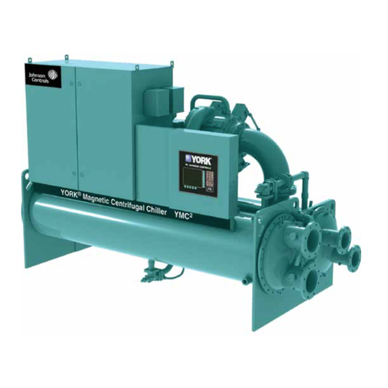
Figure 1 - YMC chiller components System components The motor includes angular contact ball bearings only The YORK Model YMC Centrifugal Liquid Chiller for control of the rotor during shutdown after rotation is completely factory-packaged including evaporator, is stopped or during shutdown due to loss of power to... -
Page 8: Heat Exchangers
Form 160.78-O1 Section 1 - System fundamentals Issue date: 05/19/2021 Heat exchangers Evaporator and condenser shells are fabricated from must be entered at chiller commissioning by a qualified rolled carbon steel plates with fusion welded seams. service technician. Only a qualified service technician Heat exchanger tubes are internally enhanced type. -
Page 9: Variable Speed Drive
At reduced capacity requirements where con- System operation description denser pressure is also reduced, the motor speed is re- The YORK Model YMC Chiller is commonly applied duced as much as possible while maintaining chilled to large air conditioning systems, but may be used on water temperature and sufficient pressure differen- other applications. - Page 10 Form 160.78-O1 Section 1 - System fundamentals Issue date: 05/19/2021 A final optional means to reduce capacity called hot Regardless of chiller compressor model, the chiller gas bypass (HGBP) is available regardless of compres- also has a mechanism called variable geometry dif- sor model.
-
Page 11: Figure 3 - Refrigerant Flow-Through Chiller
Form 160.78-O1 Section 1 - System fundamentals Issue date: 05/19/2021 ROTOR COOLING GAS VENT (M1B-197FAA and M1B-205FAA) COMPRESSOR HOT GAS BYPASS VALVE PRE-ROTATION VANES DISCHARGE (M1B-197FAA and M1B-205FAA) CHECK VALVE SUCTION DISCHARGE LIQUID LEVEL ISOLATION VALVE VALVE EVAPORATOR CONDENSER SUCTION BAFFLE SUB-COOLER ISOLATION... - Page 12 Form 160.78-O1 Issue date: 05/19/2021 THIS PAGE INTENTIONALLY LEFT BLANK. JOHNSON CONTROLS...
-
Page 13: Section 2 - System Operating Procedures
Condenser water temperature control start the pump. The Control Center will not al- low the chiller to start unless chilled liquid flow The YORK YMC chiller is designed to use less power by taking advantage of lower than design temperatures is established through the unit. -
Page 14: Operating Inspections
Form 160.78-O1 Section 2 - System operating procedures Issue date: 05/19/2021 is available for this purpose. Figure 4 shows an ex- Daily ample log sheet used by Johnson Controls Personnel 1. Check OptiView™ Control Center displays. for recording test data on chiller systems. Log sheets 2. -
Page 15: Weekly
Form 160.78-O1 Section 2 - System operating procedures Issue date: 05/19/2021 7. Check for any signs of dirty or fouled condenser To stop the chiller, complete the following steps: tubes. The temperature difference between water 1. Push the soft shutdown key on the Home screen leaving condenser and saturated condensing tem- of the OptiView panel. - Page 16 Form 160.78-O1 Issue date: 05/19/2021 THIS PAGE INTENTIONALLY LEFT BLANK JOHNSON CONTROLS...
-
Page 17: Section 3 - Maintenance
Form 160.78-O1 Issue date: 05/19/2021 Section 3 - Maintenance Renewal parts To test with R-22, complete the following steps: For any required Renewal Parts, refer to the YMC Unit Renewal Parts Manual (Form 160.78-RP1). 1. With no pressure in the system, charge R-22 gas into the system through the charging valve to a Checking system for leaks pressure of 2 psig (14 kPa). -
Page 18: Vacuum Testing
Form 160.78-O1 Section 3 - Maintenance Issue date: 05/19/2021 Table 1 - System pressures *Gauge Absolute Boiling Inches of temperatures mercury (Hg) Millimeters below one psia of mercury Microns water standard (Hg) °F atmosphere 0 in. 14.6960 760.00 760,000 10.240 in. 9.6290 500.00 500,000... -
Page 19: Vacuum Dehydration
Form 160.78-O1 Section 3 - Maintenance Issue date: 05/19/2021 the shells. If a source of hot water is not readily Operation available, use a portable water heater. Do not use A refrigerant system can be dehydrated using this steam. method because the water present in the system reacts to changes in a similar way that a refrigerant does. -
Page 20: Refrigerant Charging
Form 160.78-O1 Section 3 - Maintenance Issue date: 05/19/2021 When this point is reached, practically all of the air system pressure is raised above the point correspond- has been evacuated from the system, but there is still ing to the freezing point of the evaporator liquid. For a small amount of moisture left. -
Page 21: Handling Refrigerant For Dismantling And Repairs
Form 160.78-O1 Section 3 - Maintenance Issue date: 05/19/2021 Handling refrigerant for dismantling and dition. repairs Cleaning evaporator and condenser tubes If it becomes necessary to open any part of the refriger- Evaporator ant system for repairs, it will be necessary to remove the charge before opening any part of the unit. -
Page 22: Tube Cleaning Procedures
Form 160.78-O1 Section 3 - Maintenance Issue date: 05/19/2021 Tube cleaning procedures Testing for evaporator and condenser tube leaks Brush cleaning of tubes Evaporator and condenser tube leaks in R-134a sys- If the tube consists of dirt and sludge, it can usually tems may result in refrigerant leaking into the water be removed by means of the brushing process. -
Page 23: Compressor
Form 160.78-O1 Section 3 - Maintenance Issue date: 05/19/2021 of leakage, the corks may blow from the end of a 6. If any of the tube sheet joints are leaking, the leak tube, indicating the location of the leakage. If not, should be indicated by the detector. -
Page 24: Maintenance Inspections For York Ymc Chillers
Form 160.78-O1 Section 3 - Maintenance Issue date: 05/19/2021 Maintenance inspections for YORK YMC Monthly (or more often as required) chillers • Log and compare the VSD input voltage current for balanced values in the readings. To avoid serious operating difficulty, follow a regular inspection procedure. -
Page 25: Section 4 - Troubleshooting
Form 160.78-O1 Issue date: 05/19/2021 Section 4 - Troubleshooting Table 3 - Operation analysis chart Results Possible cause Remedy 1. Symptom: abnormally high discharge pressure Temperature difference between Condenser tubes dirty condensing temperature and water off Clean condenser tubes. Check water conditioning. or scaled. - Page 26 Form 160.78-O1 Issue date: 05/19/2021 THIS PAGE INTENTIONALLY LEFT BLANK JOHNSON CONTROLS...
-
Page 27: Table 4 - Si Metric Conversion
Form 160.78-O1 Issue date: 05/19/2021 The following factors can be used to convert from English to the most common SI metric values. Table 4 - SI metric conversion Measurement Multiply English unit By factor To obtain metric unit Capacity Tons refrigerant effect (ton) 3.516 Kilowatts (kW) Power... - Page 28 5000 Renaissance Drive, New Freedom, Pennsylvania USA 17349 1-800-524-1330 Subject to change without notice. Printed in USA Copyright © by Johnson Controls 2021 www.johnsoncontrols.com ALL RIGHTS RESERVED Form 160.78-O1 (521) Issue Date: May 19, 2021 Supersedes: 160.78-O1 (820)
Need help?
Do you have a question about the YMC2 A and is the answer not in the manual?
Questions and answers