Table of Contents
Advertisement
Quick Links
Advertisement
Table of Contents
Troubleshooting

Related Manuals for Barco IEX Series


Summary of Contents for Barco IEX Series
- Page 1 IEX series Installation & user guide ENABLING BRIGHT OUTCOMES...
- Page 2 Barco NV Beneluxpark 21, 8500 Kortrijk, Belgium www.barco.com/en/support www.barco.com Registered office: Barco NV President Kennedypark 35, 8500 Kortrijk, Belgium www.barco.com/en/support www.barco.com...
- Page 3 Changes Barco provides this manual 'as is' without warranty of any kind, either expressed or implied, including but not limited to the implied warranties or merchantability and fitness for a particular purpose. Barco may make improvements and/or changes to the product(s) and/or the program(s) described in this publication at any time without notice.
-
Page 5: Table Of Contents
Setting Coefficients for a New Receiving Card ..................33 4.3.6 Setting Coefficients for a New Module......................35 4.3.7 Replace Module with Flash ...........................36 4.3.8 Pre-storing Picture..............................37 Software Control Setting................................39 4.4.1 Setting Coefficients for a New Module......................39 5 LED Display Playing Setting...............................43 R5915190 /01 IEX series... - Page 6 Replacement of Module ............................69 7.2.2 Replacement of Power Supply ..........................70 7.2.3 Replacement of Receiving Card.........................72 8 Packaging Transportation and Storage ...........................75 Packaging ......................................76 Transportation....................................76 Storage .........................................76 A Environmental information................................77 Turkey RoHS compliance................................78 Disposal information..................................78 Contact information..................................78 R5915190 /01 IEX series...
-
Page 7: Safety
Read and follow these “warnings” and “cautions” as well. Clarification of the term “IEX” used in this document When referring in this document to the term “IEX” means that the content is applicable for following Barco products: •... -
Page 8: Safety Guidelines
Assembly parts are designed for intended use only in conjunction with IEX displays. Do not modify and/or replicate any component. Barco uses specific materials and manufacturing processes in order to achieve part strength. Consult Barco for assistance with custom applications. -
Page 9: Important Safety Instructions
Structural & mounting components should be kept dry, clean, lubricated (only if recommended), coated properly, and otherwise maintained in a manner consistent with part design. Barco products must be used in a manner consistent with their design and inspected on a routine basis for security, wear, deformation, corrosion and any other circumstances that may affect the load handling capability of the part. - Page 10 Safety to the mains through the power box from Barco this protection device is already incorporated and no extra measures need to be taken. If this product is connected to the mains through a power distribution box from another party, please verify that a Low Voltage Surge Protection Device according EN61643-11 or UL 1449 is in place.
-
Page 11: Proper Usage
IEX modules. • No force can be applied to the LEDs. Any LEDs damaged due to mechanical stress are not covered by the warranty. • Safety and functional features of the display cannot be defeated. R5915190 /01 IEX series... -
Page 12: Led Display Humidity Precautions
• Only Barco cables specified to be used with the IEX display are to be used to connect components in the IEX wall. Further, care must be taken to connect signal only according to the installation manual. -
Page 13: Product Introduction
Scope of Applications ........................20 About IEX series The IEX series is a new generation of small pitch LED display product launched by Barco. Designed for HD display application scenarios, with high protection, high reliability, stable pictures, wide viewing angle, the IEX series supports wide-range adjustment of the color temperature and brightness. -
Page 14: Features
4. High-precision structure and fine adjustment of joints. 5. With the flash memory chip, calibration data is saved at module. 6. Wide color gamut, and adjustable brightness and colour temperature, making it available for different application sites. R5915190 /01 IEX series... -
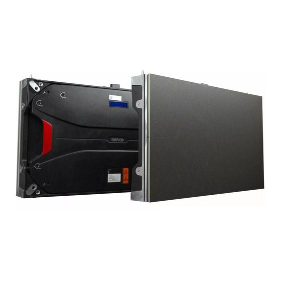
Page 15: Cabinet Appearance
Product introduction 2.2 Cabinet Appearance Overview Image 2–1 Cabinet appearance Upper/lower shoulder screw hole Signal and power socket Positioning pin Screw hole of fixing rear cover Monitoring LCD Handle Test button R5915190 /01 IEX series... -
Page 16: Specifications
Redundant power supply Optional Concave curvature Up to 5° inter-tile Dimensions 600 x 337.5 x 74mm (WxHxD) / 23.62 x 13.29 x 2.91 inch (WxHxD) Aspect ratio 16:9 Serviceability Front and back access Cables No external cabling R5915190 /01 IEX series... - Page 17 600 x 337.5 x 74mm (WxHxD) / 23.62 x 13.29 x 2.91 inch (WxHxD) Aspect ratio 16:9 Serviceability Front and back access Cables No external cabling Weight / Tile 8 kg / 17.6 lbs Warranty Extended warranty up to 5 years R5915190 /01 IEX series...
- Page 18 No external cabling Weight / Tile 8 kg / 17.6 lbs Warranty Extended warranty up to 5 years IEX2.5 Pixel pitch 2.5 mm Pixels per tile 240 x 135 (HxV) Brightness >600 nit LED lifetime 100,000h R5915190 /01 IEX series...
-
Page 19: System Solution
Extended warranty up to 5 years 2.4 System Solution System parts The display system can consist of the LED display, sending box, control PC, matrix, splicing controller and power distribution box. The following shows a topology of the system for reference: R5915190 /01 IEX series... -
Page 20: Scope Of Applications
Image 2–2 System topology 2.5 Scope of Applications Overview The IEX series products can be assembled seamless into a screen of any size and are extensively used as fixed LED displays for corporate, control room, and TV studio visualization. R5915190 /01... -
Page 21: Installation And Wiring
Installation and Wiring Package inspection........................22 General installation ........................22 Fixed installation...........................22 Wiring for LED Display ........................24 Signal and Power Cable Connection ....................24 R5915190 /01 IEX series... -
Page 22: Package Inspection
Installation and Wiring 3.1 Package inspection What should be checked Check the package for damage. If intact, check the main components against the shipping list. If any inconsistency is found, contact Barco in time. The main components include: • cabinets, •... - Page 23 M8 x 75 inner hexagon bolt M8 x 75 inner hexagon bolt Front installation hole Rear installation hole Image 3–5 Front side mounting plate Image 3–6 Rear side mounting plate Image 3–7 M8x75 inner hexagon bolt R5915190 /01 IEX series...
-
Page 24: Wiring For Led Display
(Height). Signal cables shall be connected based on the wiring diagram of the delivered products for the project. Image 3–12 Signal cable connection diagram Remark: • Nerwork cable: cat5e • System: 1 sending card 32 receiving cards. R5915190 /01 IEX series... - Page 25 (Height). Power cables shall be connected based on the wiring diagram of the delivered products for the project. Image 3–13 Power cable connection diagram Remark: • Main line (3x2.5mm): copper cable. Image 3–14 • The max power consumption for Single cabinet is 0.160kW. R5915190 /01 IEX series...
- Page 26 Installation and Wiring R5915190 /01 IEX series...
-
Page 27: Led Display Control Setting
LED Display Control Setting Power-on testing ..........................28 Starting the hardware........................28 Software Control Setting .......................28 Software Control Setting .......................39 R5915190 /01 IEX series... -
Page 28: Power-On Testing
You can follow the software installation wizard to install the software. 4.3.2 Display Configuration How to start up Run NovaLCT-Mars. Make sure that Control System on the main window is 1 Click the User option and select Advanced Login. R5915190 /01 IEX series... - Page 29 The screen configuration is updated with the information of the selected port. Sending Board setup Click Sending Board and set Sending Board Resolution (1920×1080 recommended). Set Graphics Output Resolution to the same value as Sending Board Resolution. R5915190 /01 IEX series...
- Page 30 Click Load File to load the file xxxx.rcfg stored on the optical disk. Click Send to HW. After sending, confirm that the loaded picture received by scan board is normal on the screen. Click Save. Screen connection Click Screen connection. R5915190 /01 IEX series...
-
Page 31: Brightness Adjustment
4.3.3 Brightness Adjustment General On the main window, click Brightness to display the brightness adjustment interface. Image 4–10 Main window advanced user - Brightness There are four brightness adjustment modes: • Manual • Schedule • Auto R5915190 /01 IEX series... -
Page 32: Correction Coefficient Management
4.3.4 Correction Coefficient Management About correction coefficient The IEX series products have been subject to correction before shipment. To ensure the optimum displaying effect of the screen, you need to activate the correction function when using the LED display, and to reload the correction coefficients after replacing the modules or receiving card. -
Page 33: Setting Coefficients For A New Receiving Card
Reset Correction Coefficients: Reset the calibration coefficients on whole or selected section of LED display. 4.3.5 Setting Coefficients for a New Receiving Card How to set Select Topology or List. Image 4–14 Selecting area for new receiving card R5915190 /01 IEX series... - Page 34 Select Stable Upload and click Next. Image 4–16 Uploading correction coefficients Adjust Coefficient: Perform a simple adjustment if the displaying effect is not good enough after you upload the coefficient. Then click Next. Image 4–17 Simple adjustment R5915190 /01 IEX series...
-
Page 35: Setting Coefficients For A New Module
Image 4–19 Selecting cabinet for the new module Select the position of the receiving card where the new module is located. Double click the selected position Next to Display Mode, select Modules. Select the position of the new module and click Next. R5915190 /01 IEX series... -
Page 36: Replace Module With Flash
The module of IEX has Flash, which can save the calibration coefficient. After replacing the module, make sure that the receiving have read coefficient from the Flash and save. How to replace Click Setting on the main window. R5915190 /01 IEX series... -
Page 37: Pre-Storing Picture
On the Pre-store Picture interface, you can save a picture as the prestored picture for the screen. This pre- stored picture can be set as a screen displayed upon booting, signal cable disconnection, or DVI signal absence. On the main window, click Tool and select Prestore Picture. R5915190 /01 IEX series... - Page 38 No DVI Signal: Set the picture to be displayed in the period in which the screen does not receive any DVI signals. Click Send to the settings to the hardware (the settings will be lost if you do not click Save to Hardware). R5915190 /01 IEX series...
-
Page 39: Software Control Setting
Image 4–26 Screen size and count In the main window, click Control → By Point Calibration → Brightness Calibration. Image 4–27 Main window - Control The Brightness calibration interface opens. Click Get Screen Information → Read. R5915190 /01 IEX series... - Page 40 Enter the location of the module that needs to resend the correction coefficient. Image 4–30 Starting point setting Selecting a correction coefficient file for the module of the corresponding area. After importing the calibration file, click Send to enable brightness correction. R5915190 /01 IEX series...
- Page 41 Open the LED screen setting window, on the screen parameter page 1. Next to Calibration Mode select Brightness. 2. Next to Calibration select From Receiver Card. 3. Click Save to Receivers. Image 4–32 LED Screen Setting R5915190 /01 IEX series...
- Page 42 LED Display Control Setting R5915190 /01 IEX series...
-
Page 43: Led Display Playing Setting
5.12 LED Display Playing Setting - Playing the Program .................58 5.13 LED Display Playing Setting - Edit Window ..................58 5.14 LED Display Playing Setting - Timed Playback and Control ..............59 5.15 LED Display Playing Setting - Timed Playback and Control ..............59 R5915190 /01 IEX series... -
Page 44: Selecting A Playing Solution
Image 5–1 Switching schedule mode On the editing mode setting window, select Professional playing program and click OK. Image 5–2 Edit mode setting 5.2 Playing Setting Display window settings Run the NovaStudio, click Settings and select Display Setting. R5915190 /01 IEX series... - Page 45 This function can prevent damages to the uploaded data caused by forcible exit of the software. Enable Auto Play: If you enable this function and specify a playing solution for the screen, the software will automatically activate the specified playing solution once the software is started. R5915190 /01 IEX series...
-
Page 46: Professional Playing Solution - Edit Time Segment
Edit the properties of the playing solution After adding a general time segment or interstitial segment, click General Segment 1 to edit the properties displayed in the segment editing area on the right side. Image 5–6 R5915190 /01 IEX series... -
Page 47: Professional Playing Solution - Edit Program Page
If you select Cycle, the current program page will be played cyclically all the time. When the current program page is played, the background picture or colour of the program page is displayed in the area not covered by the display window. R5915190 /01 IEX series... -
Page 48: Professional Playing Solution - Edit Display Window
Adding a display window. After adding a program page, you need to add a display window to this program page. Click Add Window on the toolbar of the program page to add a window to the current program page. R5915190 /01 IEX series... - Page 49 1. Directly specify the new location and size in the setting pane. Image 5–13 Set Window size 2. Click the display window on the screen and adjust its size by using the mouse. R5915190 /01 IEX series...
-
Page 50: Professional Playing Solution - Edit The Media
How to edit Add the media. The type of window for adding the media is Common Window. Click Add Media button of a common window to select media of different types to be added into the media list. R5915190 /01 IEX series... - Page 51 Different media have different properties. After a medium in the media list is selected, the property page of this medium is displayed below the selected medium. On this property page, you can change the properties of the medium. Image 5–19 Properties of Medium R5915190 /01 IEX series...
- Page 52 Image 5–21 Changing the Media Playing Times - Modify Right click the media to perform operations on the selected media. Image 5–22 Media Operation menu Right click a blank area in the media playlist. A media playing menu is displayed. R5915190 /01 IEX series...
-
Page 53: Professional Playing Solution - Play Media
Image 5–25 Clicking Pause or Stop on the toolbar can pause or stop the currently played program. you can also perform this operation by using the operation menu that appears when you right click the display window. R5915190 /01 IEX series... -
Page 54: Saving And Opening A Playing Solution
After a playing solution is created, you can click Schedule on the toolbar and select Save or Save As to save the playing solution in the format of xxxx.plym. Image 5–28 Saving a Playing Solution File R5915190 /01 IEX series... -
Page 55: Led Display Playing Setting - Set The Count And Size Of The Screen
Global Page: The program page that is played continuously during playback, can contain multiple windows. Only one global page can be set per screen. Normal Page: The normal page can contain multiple windows, and each normal page can have different window layouts. R5915190 /01 IEX series... - Page 56 After creating the program page, click the Add button (“+”) or right click on the program page node to bring up the add program window menu. Image 5–33 Add Program Window menu After adding the file window, select the file window and click the Add button (“+”) to select the desired material. R5915190 /01 IEX series...
-
Page 57: Led Display Playing Setting - Adjust Window Position And Size
Set it in the window properties. Image 5–36 Window Properties • Coordinate X: It lies on the top left corner of the window in pixels, which is accordingly on the left boundary of the LED screen. R5915190 /01 IEX series... -
Page 58: Led Display Playing Setting - Playing The Program
5.13 LED Display Playing Setting - Edit Window Delete Select the material/window to be deleted, click the delete button to delete the material/window; or right click on the material/window to be deleted, and in the pop-up options, click Delete. R5915190 /01 IEX series... -
Page 59: Led Display Playing Setting - Timed Playback And Control
Image 5–39 Control - Timing Command List Click Add... to add an instruction. In the Timing Command List window, set the execution content and time of the instruction. If there are multiple instructions, repeat the operation. R5915190 /01 IEX series... - Page 60 LED display, show off LED display, set brightness, show LED play screen, hide LED play screen, restart this application, close this application, restart computer, shut down computer. Image 5–42 Settings Timing Command List R5915190 /01 IEX series...
-
Page 61: Startup, Shutdown, And Maintenance
Startup, Shutdown, and Maintenance Startup Sequence.........................62 Shutdown Sequence........................62 Daily Maintenance ........................62 Warm-up Operation ........................62 Warm-up Operation - Setting the Pre-stored Picture - NovaLCT ............62 Warm-up Operation - Ageing Operation..................63 Warm-up Operation - Aging Operation ...................64 R5915190 /01 IEX series... -
Page 62: Startup Sequence
For details about how to set the prestored picture, refer to xxxx. Select a black background picture. Set Boot Screen to 60 seconds. Set both Cable Disconnect and No DVI Signal to Prestored Picture. Then click Save to Hardware. R5915190 /01 IEX series... -
Page 63: Warm-Up Operation - Ageing Operation
It is recommended that manual brightness adjustment be finished within 60 seconds. Return to the main window. Click Display Control to enter the Screen Control interface. Set Self Test to White. Click Send to finish the operation. R5915190 /01 IEX series... -
Page 64: Warm-Up Operation - Aging Operation
If the display is not used for 14 consecutive days, please follow the instructions below for aging before using it again. In the main window, click Test - Aging Test to enter the aging interface. Drag the playback window on the software to the display area of the display. R5915190 /01 IEX series... - Page 65 Startup, Shutdown, and Maintenance Image 6–6 Aging test Image 6–7 Screen test R5915190 /01 IEX series...
- Page 66 Startup, Shutdown, and Maintenance R5915190 /01 IEX series...
-
Page 67: Troubleshooting And Component Replacing
Troubleshooting and Component Replacing Common Faults and Troubleshooting Methods ................68 Replacement of Main Components ....................69 R5915190 /01 IEX series... -
Page 68: Common Faults And Troubleshooting Methods
The receiving card program is incorrect. Troubleshooting method • Check whether the receiving card signal cable and hub card in the cabinet are connected correctly. • Check the receiving card program for the cabinet or check the receiving card. R5915190 /01 IEX series... -
Page 69: Failure In Lighting Up Of A Cabinet In The Display
Front maintenance steps 1. Disconnect the power, use the big magnet maintenance tool, press the tool by aiming at the center of the module to make the magnet hold the module Image 7–1 2. Remove the module R5915190 /01 IEX series... -
Page 70: Replacement Of Power Supply
When replacing the power supply, cut off the power supply to ensure your personal safety and equipment safety. When installing a new power supply, pay attention to the order of the power cables to prevent short circuits. Replace a power supply of the LED display based on the following steps: R5915190 /01 IEX series... - Page 71 2. Disconnect the AC power input & DC power output (5 cables). Image 7–7 3. Remove the power supply and replace it. Image 7–8 Back maintenance steps Use a screw driver to remove 4 bolts which fixed the back cover. R5915190 /01 IEX series...
-
Page 72: Replacement Of Receiving Card
Replace receiving card of the LED display based on the following steps: Front maintenance steps Disconnecting the power supply and remove the module, use a screw driver to remove the bolts which fixed the receiving card R5915190 /01 IEX series... - Page 73 Use a screw driver to remove 4 bolts which fixed the back cover. Image 7–15 Pull out the connecting cable of the back cover and remove the back cover, then you can see the receiving card Image 7–16 Remove the receiving card. R5915190 /01 IEX series...
- Page 74 Troubleshooting and Component Replacing Image 7–17 R5915190 /01 IEX series...
-
Page 75: Packaging Transportation And Storage
Packaging Transportation and Storage Packaging............................76 Transportation ..........................76 Storage............................76 R5915190 /01 IEX series... -
Page 76: Packaging
Packaging Transportation and Storage 8.1 Packaging Overview The IEX series products would be packaged with anti-static EVA foam cotton carton and carton outside the cabinet. 8.2 Transportation Overview The cabinets must be packaged before transportation. The product shall not be placed upside down or horizontally, and must be protected against the wind, rain, direct sunlight, and corrosive liquid during transportation. -
Page 77: A Environmental Information
Environmental information R5915190 /01 IEX series... -
Page 78: Turkey Rohs Compliance
Registered office address: President Kennedypark 35, 8500 Kortrijk, Belgium Contact address: Beneluxpark 21, 8500 Kortrijk, Belgium Importers contact information To find your local importer, contact Barco directly or one of Barco's regional offices via the contact information given on Barco's web site, www.barco.com. R5915190 /01... - Page 80 R5915190 /01 | 2022-11-30 www.barco.com...
Need help?
Do you have a question about the IEX Series and is the answer not in the manual?
Questions and answers