Table of Contents
Advertisement
Quick Links
Advertisement
Table of Contents

Subscribe to Our Youtube Channel
Related Manuals for Ruck Ventilatoren ROTO KOMPAKT


Summary of Contents for Ruck Ventilatoren ROTO KOMPAKT
- Page 1 Assemb ly an d Op er ati n g M an u a l ROTOLINE ROTO KOMPAKT ROTO K 1050 V WOJL RLI 700 FC ROTO K 1700 V WOJL RLI 900 FC ROTO K 2800 V WOJL RLI 1200 FC...
- Page 2 The original manual has been pro- duced in the German language. Information updated: print 03.12.2021 We reserve the right to make changes ruck Ventilatoren GmbH Max-Planck-Str. 5 D-97944 Boxberg-Windischbuch Tel. +49 7930 9211-0 Fax +49 7930 9211-150 info@ruck.eu...
-
Page 3: Table Of Contents
English Assembly and Operating Manual Contents Important information ................5 1.1. Rules and regulations ..............5 1.2. Guarantee and liability ..............5 General safety instructions ..............5 2.1. Intended use .................. 5 2.2. Improper use .................. 6 2.3. Personnel qualifications ..............6 2.4. - Page 4 English 9.9.2.1. Timer on and off switching ............34 9.9.3. Setting day - night switch-over ............. 35 9.9.4. System drawings ................36 9.10. Functions ..................37 9.10.1 Fan error message contact ............37 9.10.2 Hot water coil ................37 9.10.3 Version with electric heating coil ..........37 10.
-
Page 5: Important Information
English Important information This manual contains important information on the safe and appropriate assembly, transport, commission- ing, operation, maintenance, disassembly and simple troubleshooting of the product. The product has been manufactured according to the accepted rules of current technology. There is, however, still a danger of personal injury or damage to equipment if the following general safety instructions and the warnings before the steps contained in these instructions are not complied with. -
Page 6: Improper Use
English 2.2. Improper use Any use of the product other than described in chapter “Intended use” is considered as improper. The following points are improper and dangerous: Delivery of explosive and flammable media or operation in potentially explosive atmospheres. • Delivery of aggressive and abrasive media. -
Page 7: Adhere To The Following Instructions
English 2.5. Adhere to the following instructions 2.5.1. General instructions Observe the provisions for accident prevention and environmental protection for the country • where the product is used and at the workplace. Persons who assemble, operate, disassemble or maintain ruck products must not consume •... -
Page 8: Safety Labels On The Product
English 2.6. Safety labels on the product 140605 • General warning • Electricity warning (hazardous voltage)! » Failure to observe the warnings may result in personal » Failure to observe the hazard may result in death, injury and / or damage to property. injury or damage to property. -
Page 9: Delivery Contents
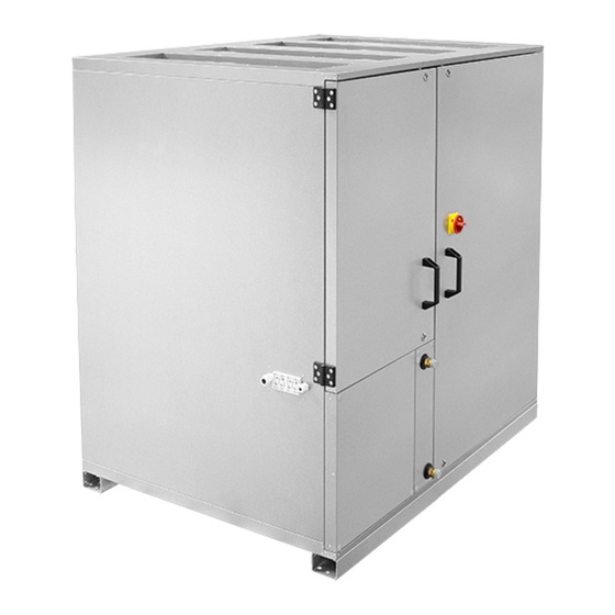
English Delivery contents Included in delivery depending on model type: 1 x ROTO KOMPAKT V, air handling unit • 1 x remote control with control cable • 1 x installation and operating manual • Product and Performance description The ROTO K is a ventilation device with integrated rotating heat exchanger for optimum heat and mois- ture recovery. - Page 10 English Legend Units / Model: ROTO K ... V Heating coil / Heater Frost protection controller Supply air temperature sensor Controller board Safety labels Cover for terminal box Terminal Box Duct Air filter M5 - extract air Rotating heat exchanger Air filter F7 - supply air EC centrifugal fan 1399...
-
Page 11: Transport And Storage
English Transport and storage Transport and storage should only be performed by specialist personnel in accordance with the installation and operating manual and regulations in force. The following points should be noted and followed: Check the delivery according to the delivery note to ensure it is complete and correct and check for •... -
Page 12: Permitted Installation Positions
English 6.1. Permitted installation positions Exclusive mounting in upright position, connection nozzles upwards. 6.2. Duct connections The air tubing has to be executed in such a manner that no condensate/rain or snow from the air duct can enter the unit. Insulate cold ducts in warm rooms. -
Page 13: Electrical Connection
English Injection circuit The combination of these circuits is the injection circuit, which is generally recommended. Fig. 5c: Injection circuit Electrical connection • Electricity warning (hazardous voltage)! » Failure to observe the hazard may result in death, injury or damage to property. →... -
Page 14: Overcurrent Protection
English Fig. 7: Connection compartment (1) Controller board (2) Cover for terminal box (3) Cable duct Fig. 8: Cable glands (4) Cable gland power supply (5) Cable gland sensors / actuators (6) Cable gland Control unit 7.1. Overcurrent protection The unit may only be operated with the correct overcurrent protection. •... - Page 15 English connected must be inherently safe and block-proof. Electrical connection with Vmax =230 VAC and Imax=2 A. Fire detector An external, potential-free fire detection contact switches the device off. The display indicates “Error fire protection”. This signals requires a manual reset. Modbus RTU The communication interface with Modbus RTU protocol is already integrated as standard.
-
Page 16: Commissioning
English Control unit The control unit is connected to the supply air unit’s control system with a control cable. A connector on the control cable is plugged directly into the socket on the control unit from beneath (see Fig. 9). On the unit, the control cable is first fed through a cable gland (see Fig. 8), placed in the cable duct and then connected to the RJ10 socket provided in the controller board. -
Page 17: Operation
English Operation 9.1. Control unit The control unit allows the selection and the command of various unit functions. The control unit has an integrated temperature sensor (set-point sensor) for measuring the room temperature. The display shows the various operating parameters and error messages. You can switch between dis- playing different menu points and make changes to your unit settings and values. -
Page 18: Changing Setpoint Temperature And Fan Steps
English 9.3. Changing setpoint temperature and fan steps Switching the unit on/off on the control unit. 10:44 By selecting „ON/OFF“, the unit is switched on or off The unit‘s status now appears on the display with the current values. » Set-point temperature display »... -
Page 19: Adjustment Of The Control Unit Parameter
English 9.5. Adjustment of the control unit parameter To access the menu for setting the control unit parameters, you have to touch the „Settings“ icon. 9:51 The display shows the selection menu. By touching the desired icon, you can change between the 9:51 parameters you need. -
Page 20: Display User Level
English 9.6. Display user level You access the menu of the user level by touching the „Settings“ icon. The selection menu will then 9:51 appear on the display. 21,0°C Selection menu 9:51 You can see the actual values by touching the „Actual values“ icon. Actual values Display only, no changes are possible. - Page 21 English Control unit outputs 9:51 OUTPUT Display of the assigned outputs on the control unit. UNUSED 0001001001010001 9:51 Position: Consequence: Description: OUTPUT unimplemented UNUSED UNUSED unimplemented UNUSED 0001001001010001 ENABLE COLDNESS 1 = on 1 = on ROTOR MOTOR UNUSED unimplemented 1 = opening HEAT.VALVE OPEN HEAT.VALVE CLOSE...
-
Page 22: Menu Level Operating Parameters (Qualified Personnel) Roto K
English 9.7. Menu level Operating parameters (qualified personnel) ROTO K 9:51 You can access the Commissioning level by selecting the „Settings“ icon. The display then shows 21,0°C the selection menu. Selection menu 9:51 Now you can access the Operating parameters by touching the „Operating parameters“ icon. It is necessary to provide a password. This will remain valid for 30 min. After 30 minutes it is neces- 9:51 sary to retype the password in order to continue making changes. - Page 23 English P 15 Minimum ventilation supply air / P 16 Minimum ventilation extract air 9:51 The volumetric flow can also be adjusted to „MINIMUM VENTILATION“ (night setback). This param- SUPPLY AIR eter is controlled using the timer switch or Level 1 and can be set across the entire air volume range. MIN.VENT 650 m³/h 9:51...
- Page 24 English Sensor type -CO2- P 14 Sensor type CO2 9:51 Volumetric flow, demand controlled by CO2 of the extract air SENSORTYPE W/O EXT.SENSOR 9:51 SENSORTYPE W/O EXT.SENSOR Factory setting 9:51 9:51 SENSORTYPE SENSORTYPE P 23 and P 24 9:51 These settings can be found in the measuring range of the used measuring transducer. The measur- EXT.SENSOR ing range is already preset for devices with integrated CO2 sensor.
- Page 25 English Sensor type -VOC- P 14 Sensor type VOC 9:51 Volumetric flow, demand controlled by external measuring transducer (VOC) SENSORTYPE W/O EXT.SENSOR 9:51 SENSORTYPE W/O EXT.SENSOR Factory setting 9:51 SENSORTYPE 9:51 9:51 SENSORTYPE SENSORTYPE P 23 and P 24 9:51 These settings can be found in the measuring range of the used measuring transducer.
- Page 26 English Sensor type -EXT.CTRL.- P 14 External control 9:51 External volume flow control via 0 - 10 V input (see wiring diagram). SENSORTYPE W/O EXT.SENSOR 9:51 SENSORTYPE W/O EXT.SENSOR Factory setting 9:51 SENSORTYPE 9:51 SENSORTYPE 9:51 9:51 SENSORTYPE SENSORTYPE EXT.CTRL. EXT.CTRL.
-
Page 27: Control Type Roto K-P: Constant Pressure Control
English 9.7.2. Control type ROTO K-P: Constant pressure control P 13 ROTO K-P Constant pressure control 9:51 Operating mode P is the common control mode for the operation with variable air volumes by variable air volume controllers. The desired supply and extract air pressure can be set with the control unit. Two pressure sensors SEN P are necessary for this operating mode. -
Page 28: Control Type Roto K-Pv: Constant Pressure Control With Balanced Air Volume
English 9.7.3. Control type ROTO K-PV: Constant pressure control with balanced air volume P 13 ROTO K-PV Constant pressure control with balanced air volume 9:51 The operating mode PV is set for air-tight low-energy houses with variable air volumes by variable air volume controllers. - Page 29 English The following parameters are for all types of control: P 21 Room, supply or extract air temperature regulation 9:51 The room, supply air or extract air temperature regulator compares the air temperature measured at the temperature sensors with the reference temperature set on the control unit In the case of heating, a difference between the set-point and actual temperature SUP.AIR TEMP.CON causes the controller to increase or reduce the heat output.
- Page 30 English P 22 Heating and cooling (direct expansion) 9:51 Only with option Warm water heating coil or Electric heater* and option cooling coil. DIRECT EVAPORATO Heating: 3-point control or 0-10V HEATING-COOLING Cooling: potential-free contact ON / OFF, 3-point control or 0-10V * The electric heaters are controlled by the internal bus.
-
Page 31: Menu Level Commissionning Roto K
English 9.8. Menu level Commissionning ROTO K 9:51 You can access the parameter settings by selecting the „Settings“ icon. The selection menu will then 21,0°C appear on the display. Selection menu 9:51 Next you enter the Commissioning level by selecting the icon „Commissioning parameters“. It is necessary to provide a password. - Page 32 English P 4 I - component 9:51 A value between 5-20 can be set for the I – component. I-COMPONENT The factory setting is at 10. If the value decreases, the control becomes more sensitive. CAUTION! Due to highly sensitive settings, the control tends to pulsate. P 5 P - component 9:51 A value between 5-20 can be set for the P –...
-
Page 33: Time / Time Switch
English Room EXTRACT EXHAUST AIR KWR/DVR SUPPLY FRESH AIR Control Fig. : V1 - V2 EC centrifugal fan M1** - M2** Flap system drive Connection diagram ROTO K M5/ F7 Air filter (Class M5/F7) Rotating heat exchanger Hot water coil EHM** KWR/DVR* Cold water cooling coil / Direct evaporator... -
Page 34: Setting The Timer
English 9.9.2. Setting the timer With the setting parameters for the timer, the times when the unit is to come on (ON) or off (OFF) can 10:39 be set individually for each day of the week. 21,0°C You can switch from the Operating display to the Selection menu through the „Settings“ icon. You can access them by selecting „Timer settings“... -
Page 35: Setting Day - Night Switch-Over
English 9.9.3. Setting day - night switch-over This menu has the same functions as the timer. The only difference is that the device is not switched 10:45 on (ON) or off (OFF), but from day to night mode. The device runs in day mode with the basic ventilation volume flow. 21,0°C The device runs in night mode with the minimum ventilation volume flow. -
Page 36: System Drawings
English 9.9.4. System drawings Fig. 16: 10:39 Systematic drawing without timer settings 21,0°C Basic ventilation Day 1 Fig. 17: 10:39 10:39 Systematic drawing for timer settings DAY 1 ON 21,0°C 4:00 22:00 0:00 0:00 0:00 0:00 Basic ventilation 4:00 22:00 Day 1 Fig. -
Page 37: Functions
English 9.10. Functions 9.10.1 Fan error message contact Each motor has an error message contact which is closed during fan operation. The unit switches off when the contact opens. After correction of the fault (see 14.2. Fault diagnosis chart), the unit can then be restarted. -
Page 38: Cleaning And Care
English 10.2. Cleaning and care Servicing, troubleshooting and cleaning may only be performed by specialist personnel in ac- cordance with this installation and operating manual and the regulations in force. If operated correctly, ruck products only require a small amount of maintenance. The following work should be performed at regular intervals, in accordance with health and safety regulations: Check the operation of the control system and safety devices. -
Page 39: Air Filter
English Fig. 15 Fig. 16 Fig. 17 Remove the lower control board Opening for replacing the round belt. Removing the defective and the cover. drive belt. 128625 A (1 : 10) Fig. 19 Fig. 20 Fig. 18 Welding the drive belt (3) with clamp (1) Make sure that the belt is running Welding of the new round and welding paddle (2). -
Page 40: Changing The Battery
English Calibrate filter Status display: 9:51 The differential pressure increases as one of the air filters becomes more clogged. When the pres- 100% 100% sure reaches the value set on the corresponding pressure sensor, this can be seen on the status 21,0°C display. -
Page 41: Modbus Communication Interface
English 11. Modbus communication interface 11.1. Wiring diagram Place Jumper K 1 for the last device on the bus Signal line B with 10 kOhm to GND Signal line A with 10 kOhm to +24 V Control unit 120 Ohm Leitung Fig. -
Page 42: Parameter Table
English 11.4. Parameter table Register Protocol Parameter name Value range Data type Authority address address 40001 Reserved integer 100 - 200 corresponds 10.0 - 20.0 °C 40002 Minimum target temperature integer 40003 Maximum target temperature 200 - 350 corresponds 20.0 - 35.0 °C integer 0 = Automatic start 40004... - Page 43 English Register Parameter name Value range address ROTO K 1050 V ROTO K 1700 V ROTO K 2800 V ROTO K 4200 V ROTO K 7600 V 40016 Minimum ventilation supply air 500 - 1400 m³/h 500 - 2000 m³/h 700 - 3200 m³/h 1200 - 6200 m³/h 40017...
-
Page 44: Current Value Table
English 11.5. Current value table Register Protocol Parameter name Value range Data type Authority address address 30001 Unit identification 10000 integer 30002 Room temperature Temp in 1/10 ° - 500 to 1000 integer 30003 Supply-air temperature Temp in 1/10 ° - 500 to 1000 integer Temp in 1/10 °... -
Page 45: Expansion And Reconfiguration
English Current value table, protocol addresses 14 (outputs) Bit 0 Reserved Bit 1 Reserved Bit 2 1 = Cooling requirement Bit 3 1 = Rotor motor Bit 4 Reserved Bit 5 1 = Heating valve open Bit 6 1 = Heating valve closed Bit 7 1 = Heating pump on Bit 8... -
Page 46: Disassembling The Product
English 13.1. Disassembling the product Observe the safety instructions given in Sections 2 to 8 and Section 13 when decommissioning and disassembling the unit. 13.2. Disposal Careless disposal of the unit may be cause pollution. Please therefore dispose of the unit in accordance with the national requirements that apply in your country. - Page 47 English Faults displayed Type of fault and repair 8:37 21,0°C Battery » Battery of the remote control unit is empty » Replace battery 10:48 ERROR » The control unit has no connection. » Check the connection or replace the cable if necessary. SUPPLY AIR TEMP 8:32 FAULT...
- Page 48 English Faults displayed Type of fault and repair SAFTY THERMOSTAT 8:52 Fault in the safety thermostat - electric heating element temperature monitoring FAULT » The housing temperature is higher than 75 °C. The control circuit is broken, the electric heater is switched off. Pos- sible cause: defective supply air valve, fan has failed, etc.
-
Page 49: Technical Data
English Faults displayed Type of fault and repair NOT ENABLE 11:59 No release » The release contact is not closed. » Close the release contact. The unit can then be started. 9:51 Device is off and cannot be switched on »... -
Page 50: Appendix
English Ø Ø Fig. 27: Fig. 28: Outside dimensions of the control unit. Installation dimensions of the control unit. TeileId Control unit Size W+H+T 82+82+30 Ø W Assembly size Fig. 26: Ø D Dimensions of the supply air unit 16. Appendix 16.1. -
Page 51: Technical Drawings
English 16.2. Technical drawings ROTO K 1050 V www.ruck.eu... - Page 52 English ROTO K 1050 V - Transition Ø 315 Tel. +49 7930 9211-0 Fax +49 7930 9211-150...
- Page 53 English ROTO K 1700 V www.ruck.eu...
- Page 54 English ROTO K 1700 V - Transition Ø 400 Tel. +49 7930 9211-0 Fax +49 7930 9211-150...
- Page 55 English ROTO K 2800 V www.ruck.eu...
- Page 56 English ROTO K 2800 V - MAK Motor shut-off flap Tel. +49 7930 9211-0 Fax +49 7930 9211-150...
- Page 57 English ROTO K 4200 V www.ruck.eu...
- Page 58 English ROTO K 4200 V - MAK Motor shut-off flap Tel. +49 7930 9211-0 Fax +49 7930 9211-150...
- Page 59 English 16.3. Wiring diagrams ROTO K 1050 V Wiring diagrams No.: 144290 Power input www.ruck.eu...
-
Page 60: Wiring Diagrams
English ROTO K 1050 V Wiring diagrams No.: 144290 Power input Tel. +49 7930 9211-0 Fax +49 7930 9211-150... - Page 61 English ROTO K 1700 V Wiring diagrams No.: 139797 Power input www.ruck.eu...
- Page 62 English ROTO K 2800 V Wiring diagrams No.: 139798 Power input Tel. +49 7930 9211-0 Fax +49 7930 9211-150...
- Page 63 English ROTO K 4200 V Wiring diagrams No.: 139799 Power input www.ruck.eu...
- Page 64 English ROTO K ... V Connection diagram rotor drive Tel. +49 7930 9211-0 Fax +49 7930 9211-150...
- Page 65 English ROTO K ... V Control unit www.ruck.eu...
- Page 66 English ROTO K ... V Connection plan for parameter P14 external sensors Differenzdrucksensor Differential pressure sensor Abluft Extract air 15 - 30 V= -X15 -X14 A - In 2 3 4 5 6 7 8 9 10 11 12 13 A - In A - In 0 - 10V...
- Page 67 English External sensor (CO2, VOC) -X15 -X14 A - In 2 3 4 5 6 7 8 9 10 11 12 13 A - In A - In A - Out A - Out +24V D - In B1: Volumenstrom Zuluft / 0 - 10V Supply air flow B2: Volumenstrom Abluft /...
- Page 68 This document, as well as the data, specifica- tions and other information set forth in it, are the exclusive property of ruck Ventilatoren GmbH. It may not be reproduced or given to third parties without its consent.
Need help?
Do you have a question about the ROTO KOMPAKT and is the answer not in the manual?
Questions and answers