
Subscribe to Our Youtube Channel
Related Manuals for Siemens SD 270


Summary of Contents for Siemens SD 270
- Page 1 SD 270 Diagnostic Audiometer Operating Manual (Applies from Serial Number 8200 onwards)
-
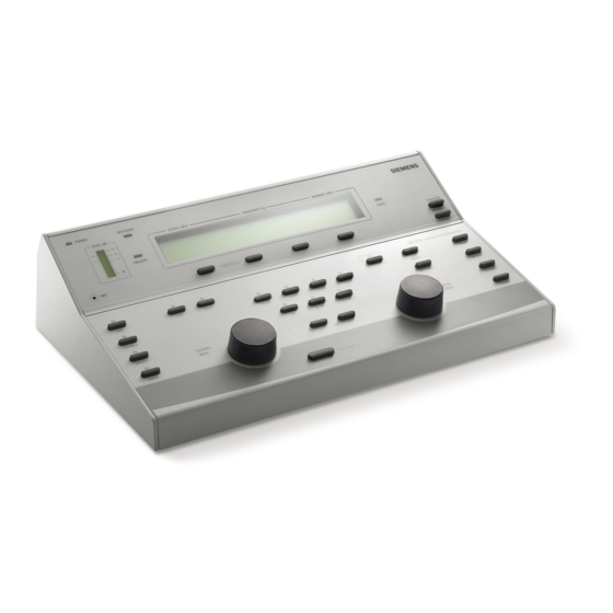
Page 2: Overview Of Sd 270 Audiometer Controls
Overview of SD 270 Audiometer Controls... -
Page 3: Table Of Contents
Contents Overview of SD 270 Audiometer Controls Contents 1 Introduction 1.1 Intended applications 1.2 Unpacking 1.3 Standard contents 1.4 Optional accessories 1.5 Frequently used functions 1.6 Known contradictions 2 Important Safety Instructions 2.1 Precautions 2.2 Electromagnetic compatibility (EMC) considerations 2.3 Mains supply operation 2.4 Audiometer connections... - Page 4 4 Sequence of Operation and Suggested Test Procedure 4.1 Pre-test 4.2 Test 4.3 Post-test 5 Specification 5.1 Output data 5.2 Maximum hearing levels provided at each frequency 5.3 Physical Data 5.4 Equipment classification 6 Symbols 7 Technical Information 8 Routine Maintenance 8.1 Audiometer maintenance 8.2 Transducer maintenance 8.3 Mains adapter maintenance...
- Page 5 5. Free Field Live Voice Speech Audiometry 6. Free Field Recorded Speech Audiometry 7. Free Field Recorded Speech Audiometry with Competing Noise (Audiometer-Generated) 8. Free Field Recorded Speech Audiometry with Competing Noise (Recorded) Appendix 2 ‒ Free Field Calibration Procedure 1.
-
Page 6: Introduction
Introduction Thank you for purchasing a Siemens audiometer. The Siemens SD 270 is a diagnostic audiometer that will give many years of reliable service if treated with care. 1.1 Intended applications The Siemens SD 270 diagnostic audiometer is designed for use by audiologists, general practitioners, hearing aid dispensers and child health professionals. -
Page 7: Optional Accessories
1.5 Frequently used functions How to switch on/off or set the language or control the level? Please refer to section 3 of this instruction. 1.6 Known contradictions There are no contradictions known for the use and application of the SD 270 Audiometer. -
Page 8: Important Safety Instructions
Safety Note! The SD 270 diagnostic audiometer must be used only by practitioners qualified to perform audiometric tests. It is intended for use as a screening and diagnostic tool. -
Page 9: Electromagnetic Compatibility (Emc) Considerations
Do not drop or otherwise impact this instrument. If the instrument is dropped or damaged, return it to the manufacturer for repair and/or calibration. Do not use the instrument if any damage is suspected. The instrument must be stored and used within the specified temperature, pressure and humidity ranges (see Sections 7 and 9). -
Page 10: Mains Supply Operation
2.3 Mains supply operation The audiometer is designed for continuous operation and is powered by a mains adapter which is supplied, and specified as part of the equipment. If a replacement is required, please contact your local Service department (see Annexx 5). All other connections must be made before connecting the output lead from the adapter into the POWER input socket on the back of the audiometer. -
Page 11: Audiometer Connections
2.4 Audiometer connections To disconnect the device from mains supply, unplug the DC-con- nector from the input socket. All the relevant accessory terminals and connections are labeled to ensure correct identification and connection as follows: Socket Socket Type Colour Connected Part Notes Label Code... -
Page 12: Data Transfer To A Printer
Safety Note! For connected parts marked * only connect the accessories supplied with the instrument. These parts have been tested for use with the Siemens SD 270 Diagnostic Audiometer for compliance with the standards IEC 60601-1 and IEC 60601-1-2. The use of accessories other than those specified may compromise compliance with these standards. -
Page 13: Data Transfer To A Computer
Please refer to Appendix 4 for important information regar- ding the connection of non-medical electrical equipment to medical electrical equipment. The Siemens SD 270 has audio line in/out connections for CD or tape player input (e.g. for recorded speech testing) and amplifier output. -
Page 14: Using The Audiometer
Using the Audiometer 3.1 Ambient conditions Audiometric testing should always be performed in a quiet room or in an acoustic booth. 3.2 Switching the audiometer on and off Press the key highlighted centre right of front panel. No warm-up time is required. The display will briefl y show the model and the type of headphones currently selected for use. -
Page 15: Testing The Patient Response Switch
3.4 Testing the patient response switch Press the patient response switch and the light labeled RESPONSE (to the left of the display) will illuminate green. 3.5 Audiometer display On start-up the display will show the following default setting: This indicates that when the PRESENT key is pressed, the tone presented will be at 30dBHL at a frequency of 1kHz (1000 Hz) to the designated ear. - Page 16 3.6.2 OPTIONS key Pressing the OPTIONS key and then using the softkeys allows the operator to step through the options (use the NEXT softkey) and modify the settings as required. Pressing the softkey below QUIT exits the options menu and saves the settings. Menu Option Description Clear test?:...
- Page 17 Load audiogram no (1): Use UP key to select the required sto- rage location and press LOAD key to retrieve test results Contrast: Adjust using the UP and DOWN keys Bone masking: Selects the headset or the optional masking earpiece as the means of mas- king;...
- Page 18 Select phones: This option is only available if a se- condary headphone is enabled; use Softkeys 1 or 2 to select the required headphone type. FF equiv speech?: This option is only available if eit- her DD45 or TDH39 is the selected headphone;...
- Page 19 Store on 2 of 3?: Automatically stores a threshold if the responses made to two out of three test signals are at the same hearing level. Set freefield levels?: This option provides access to the freefield calibration function; refer to Appendix 2 for details.
- Page 20 Display Counter?: Activates a percentage counter for use with speech testing (refer to Appendix 1). Omit 750/1k5/3k/6k?: To exclude these frequencies from those available for testing press the YES key.
- Page 21 Present Time: Select the minimum and maximum times that a stimulus can sound when the PRESENT key is pressed; either 0.5 sec (min) & 10sec (max) or 1.0 sec (min) & 2.0 sec (max). FF Speech units: The units for freefield speech may be switched between dBHL and dBSPL.
- Page 22 3.6.3 Description of Function of Other Keys SIGNAL The rotary control is used to increase or decrease the signal level in the selected step size. MASK The rotary control is used to increase or decrease the masking level in the selected step size. (The MASK key must be selected.) SINE Selects a pure tone as the test signal;...
- Page 23 PULSE Enables pulse tone present function, the indicator above the key illuminates green. INVERSE Presents the signal continuously, the indicator above the key illuminates green. Pressing the PRESENT key interrupts the signal presented. +20dB This enables tone levels to be presented with up to 20dB higher output;...
- Page 24 FREEFIELD Routes signals to LINE output socket; the indica- tor above the key illuminates green. Press the ⇦ key to lower the frequency and the ⇨ key to increase the frequency. PRESENT Press to present the displayed test signal to the test subject.
- Page 25 TALKBACK While selected (as indicated by the indicator above the key) the signal from MIC2 is routed continuously to the MONITOR output. Press the key again to de-select. The talkback level may be adjusted by the SIGNAL control while key is held down.
- Page 26 PHONES If the optional insert earphones are supplied in addition to DD45 earphones this feature will enable the operator to select the required out- put transducers. In case only DD45 headphone is installed, the display will show the message: „Only one set available“. Push Softkey 4 to quit the screen.
- Page 27 3.6.4 TEST MENU This key enables the selection of the following standard tests. Exit each test by pressing the TEST MENU key again. Menu Option Description STENG Stenger: Routes tone or speech to both ear- phones simultaneously. Use the SIGNAL rotary control to adjust the Left channel level and the MASK rotary control to adjust the right.
- Page 28 ABLB Alternate Binaural Loudness Balance: Routes tone to each earphone alternately. Use the SI- GNAL rotary control to adjust the Left channel level and the MASK rotary control to adjust the right. Pressing the PRESENT key interrupts the signal presented. SISI Short Increment Sensitivity Index: Presents a tone continuously at the level and frequency dis-...
- Page 29 • Use Softkey 1 to record a response • Use Softkey 2 to record no response • Use Softkey 3 to clear the results display • Use Softkey 4 to return to the initial SISI display...
-
Page 30: Threshold Retention Function
3.7 Threshold Retention Function This function stores the last presented combination of ear, tone and frequency for every frequency tested in the audiometer’s memory (air conduction, bone conduction and ULL). Each value is stored by pressing the STORE key. The operator can then review the results at the end of the test and record them on an audiogram card, print with the optional printer and/or transfer results to a NOAH database on a computer. -
Page 31: Uncomfortable Loudness Levels
3.8 Uncomfortable loudness levels If it is required to record uncomfortable loudness levels (ULL) then pressing Softkey 4 with Air conduction selected will enable this function. The display will be similar to that shown below, and ULL thresholds are stored and retrieved as described in Section 3.7. 3.9 Saving audiograms in internal memory The user may store up to 12 audiograms, referenced by number, in the internal memory of the audiometer. -
Page 32: Loading Audiograms From Internal Memory
3.10 Loading audiograms from internal memory Press the OPTIONS key, press NEXT repeatedly until “Load Audio- gram no.” appears on screen. Select the required audiogram (1-12), using the UP key then press the LOAD key. Press the QUIT key once confirmation that the thresholds have been retrieved appears on screen. -
Page 33: Data Transfer To A Noah Database
3.12 Data transfer to a NOAH database For transfer of test results stored within the audiometer to a NOAH database you will need the Siemens link driver disc (stock number 105 98 699). This option includes a USB cable to connect to a PC and the necessary installation & operating... -
Page 34: Sequence Of Operation And Suggested Test Procedure
Sequence of Operation and Suggested Test Procedure The following applies to air conduction measurements – refer also to ISO 8253 for further guidance. 4.1 Pre-test 1. Switch the audiometer on. 2. Perform a listening check. (see 8.4) 3. Decide whether to use the Threshold Retention Function, the Store on 2 of 3 option, or an audiogram card to record the thresholds. -
Page 35: Post-Test
11. If Store on 2 of 3 is selected, go to step 13. 12. Repeat step 10 until the patient responds three out of a ma- ximum of five times at the same signal level, indicating the patient’s hearing threshold level for that frequency; mark the threshold on an audiogram card or press the STORE key once to activate the Threshold Retention Function which displays the threshold on screen. -
Page 36: Specification
Specification 5.1 Output data Outputs: Left earphone, Right earphone, Bone (L&R) Insert masking and Freefield Frequency range (Hz): Air: 125-8kHz Bone: 250Hz-8kHz Frequency accuracy: <1% Distortion: <2% Output level range (AC): -10dBHL to 120dBHL maximum Output level range (BC): -10dBHL to 70dBHL maximum Output level range (FF): Up to 90dB Insert masking output:... -
Page 37: Maximum Hearing Levels Provided At Each Frequency
5.2 Maximum hearing levels provided at each frequency Frequency, Hz Air conduction, dBHL Bone conduction, dBHL (DD45) (B-71) ‒ 1000 1500 2000 3000 4000 6000 8000 5.3 Physical Data Display: 2 lines of 24 characters Mains Power: 100 – 240 Vac; 50/60Hz; 0.25A Dimensions: 355mm long x 230mm deep x 100mm high Weight:... -
Page 38: Equipment Classification
Mode of operation Continuous operation Equipment mobility Portable The SD 270 Audiometer is classified as a Class IIa device under Annex IX (Section 1) of the EU Medical Devices Directive. It is intended for use as a diagnostic audiometer instrument. -
Page 39: Symbols
Symbols The following symbols appear on the audiometer, the manual or mains adapter: Definition: Refer to instruction manual (mandatory) Definition: Type B applied part – an applied part provi- ding protection against electric shock, particularly regarding allowable patient leakage current and patient auxiliary current. -
Page 40: Technical Information
Technical Information Audiometer Audiometer type: Type 2 (EN60645-1) Type B-E (IEC 60645-2) Frequency Modulation Carrier frequencies: 125Hz – 8kHz as per pure tones Modulation waveform: Sinusoidal Rising and falling symmetry: Symmetrical on linear frequency scale Modulating frequency: 15.625Hz Frequency deviation: +/-10% Speech Channel Frequency response:... - Page 41 Insert Masking Earpiece Calibration method: With 2cc coupler compliant with IEC 126 Transducers Types and reference levels: DD45: ISO 389-1, Table 2 E-5A: ISO 389-2, Table 1 B-71: ISO 389-3, Table 1 Static headband force: Headphones: 4.5N Bone vibrator: 5.4N Bone vibrator calibrated: For mastoid placement Sound attenuation...
- Page 42 Patient response input: 6.3 mm Jack socket Left / Right / Bone outputs: 6.3 mm Jack socket Monitor output: Mono 3.5mm Jack socket Insert output: Mono 3.5mm Jack socket USB: Type B socket Max. voltage at any output: 12V peak...
-
Page 43: Routine Maintenance
Routine Maintenance 8.1 Audiometer maintenance The Siemens SD 270 audiometer is a precision instrument. Handle it carefully in order to ensure its continued accuracy and service. When cleaning the instrument, first disconnect it from the Mains supply. Use a soft cloth and mild detergent to clean the instrument panel when required. - Page 44 Earphones Clean the ear cushions with a recognised disinfectant, e.g. a “Mediswab”. Insert Masker Never insert or in any way use the insert masker without using a new, clean and fault-free test tip. This part is for single use only - that is, each test tip is intended to be used once only for a single ear for a single patient.
-
Page 45: Mains Adapter Maintenance
8.3 Mains adapter maintenance Before use check the mains AC adapter for signs of wear and/or damage. If you find any, please replace it immediately by contacting your local service department (see Annexx 5), requesting part number: 106 75 033. CAUTION! Do not use any other mains adapter with this instrument. -
Page 46: Instrument Storage And Transportation
Instrument Storage and Transportation Please note that this instrument can be stored or transported with the following environmental parameters: Temperature: -20°C to +70°C Humidity: 10% to 90% (non-condensing) Atmospheric Pressure: 500 hPa to 1060 hPa... -
Page 47: Calibration & Return Of The Instrument
10 Calibration & Return of the Instrument We recommend that this audiometer should be calibrated on an annual basis. Please contact our service departments for details of calibration services (see Appendix 5). Important Note: The instrument should be returned to the manufacturer for service &... -
Page 48: Guarantee
11 Guarantee All Siemens SD 270 instruments are guaranteed against faulty materials and manufacture. The instrument will be repaired free of charge for a period of one year from the date of despatch if re- turned, carriage paid, to one of the service departments listed in Annexx 5. -
Page 49: Ordering Consumables & Accessories
100 55 806 Insert earphones* 106 00 115 6 pin printer cable for audiometer to printer 105 98 699 Siemens link driver disk (NOAH) incl. USB type B cable 106 00 116 Printer (Able AP1300) 106 00 117 Thermal printer paper for Able AP1300... -
Page 50: Appendix 1 - Speech Audiometry
Appendix 1 ‒ Speech Audiometry The Siemens SD 270 audiometer may be used in the following speech modes of operation. However users should be aware that there is a growing body of professional opinion that Live Voice speech audiometry is generally not recommended. For recorded speech audiometry, only material with a stated relationship with the calibration signal should be used. -
Page 51: Test Modes In Speech Audiometry
Test Modes in Speech Audiometry Initially in speech mode either ear may be selected, with the output level controlled by the SIGNAL rotary control. Pressing TEST MENU followed by Softkey 1 routes the speech to both ears (Stenger test with speech), with the left output level controlled by the SIGNAL rotary control and the right output level controlled by the MASK rotary control. -
Page 52: Live Voice Speech Audiometry To Headphones
1. Live Voice Speech Audiometry to Headphones 1.1 Set Up Connect a microphone to the MIC1 input on the audiometer Press SPEECH and use Softkey 1 to ensure that ‘MIC’ is displayed in capitals (indicating that the external microphone is selected). The microphone is initially routed to the left earphone. -
Page 53: Live Voice Speech Audiometry With Contralateral Masking
2. Live Voice Speech Audiometry with Contralateral Masking 2.1 Set Up ‒ as described in 1.1 then Select MASK Speech-weighted masking is now routed to the opposite earphone to that selected. The MASK rotary control changes the masking level in 5dB steps. If required, readjustment of the input signal level can be accessed by temporarily deselecting the MASK key ‒... -
Page 54: Recorded Speech Audiometry To Headphones
3. Recorded Speech Audiometry to Headphones 3.1 Set Up Connect a CD, tape player, or other sound source to the LINE IN jack socket; refer to Section 2.7 of this operating manual. Press SPEECH and use Softkey 1 to ensure that ‘LINE’ is displayed in capitals (indicating that the line input is selected). -
Page 55: Recorded Speech Audiometry To Headphones With Contralateral Masking
4. Recorded Speech Audiometry to Headphones with Contralateral Masking 4.1 Set up ‒ as described in 3.1 then Select MASK. Speech-weighted masking is now routed to the opposite ear- phone to that selected. Select INT or EXT masking source using Softkey 4 (the option selected is displayed in capitals);... -
Page 56: Free Field Live Voice Speech Audiometry
5. Free Field Live Voice Speech Audiometry Important Notes ‒ Free Field Modes: For the following Free Field modes of operation it is essential for the Free Field calibration procedure described in Appen- dix 2 of this operating manual to have been performed. This aspect may also be subject to local requirements or legislati- 5.1 Set Up Connect an external amplifier/speaker to the LINE OUT jack... -
Page 57: Free Field Recorded Speech Audiometry
6. Free Field Recorded Speech Audiometry 6.1 Set Up Connect an external amplifier/speaker to the LINE OUT jack socket, and a CD, tape player, or other sound source to the LINE IN jack socket; refer to Section 2.7 of this operating manual. -
Page 58: Free Field Recorded Speech Audiometry With Competing Noise (Audiometer-Generated)
7. Free Field Recorded Speech Audiometry with Competing Noise (Audiometer-Generated) 7.1 Set Up – as described in 6.1 then Select MASK. Select internal masking source using Softkey 4 (the INT option is displayed in capitals); wideband noise is routed to the competing LINE OUT channel. -
Page 59: Free Field Recorded Speech Audiometry With Competing Noise (Recorded)
8. Free Field Recorded Speech Audiometry with Competing Noise (Recorded) 8.1 Set Up – as described in 7.1 except Select external masking source using Softkey 4 (the EXT option is displayed in capitals); competing noise from the signal source is routed to the competing LINE OUT channel. -
Page 60: Appendix 2 - Free Field Calibration Procedure
1. Assurance Of Calibration The following is a brief description of the equipment and proce- dures to be used with the Siemens SD 270 audiometer as a means of performing free-field calibration. However it must be emphasi- sed that it is the responsibility of the equipment operator to ensure that correct free field calibration has been achieved and it is recom- mended that the standards for free-field &... -
Page 61: Free-Field Speech Calibration
For calibration, the measuring microphone of a sound level meter (SLM) is placed at the reference point (the point that the subject’s head will be located). The procedures outlined below cover calibration for both speech and warble tone modes of audiometry. If both modes are to be use then speech calibration must be carried out first. - Page 62 4.1. Calibrating the Speech Channel 4.1.1. Equalisation (Optional) To perform equalisation, connect an external speech source to the audiometer (e.g. CD or tape player). From the default (switch-on) condition of the audiometer select SPEECH and FREEFIELD and then play the test signal from the speech recording. This should either •...
- Page 63 lidate any previous free-field warble tone calibration, and this must be repeated when warble tone testing is required. 4.1.2. Level Setting The calibration tone from the speech recording should be played and the external amplifier volume control used to give a reading of 90dBSPL for a 70dBHL instrument setting.
-
Page 64: Free-Field Warble Tones Calibration
5. Free-field Warble Tones Calibration 5.1. Entering Free Field Calibration Mode • Press OPTIONS and then the NEXT key to move through the menu items and access the ‘Set freefield levels’ screen. Press the YES key. • Press QUIT and you are now presented with the freefield calibration screen for Warble tones. - Page 65 If a calibration of the speech channel is not required: The output of the external amplifier should be set in order to achieve the level specified above at 1000Hz (i.e. 72dBSPL) as measured by the SLM with the audiometer set to 0dB compen- sation.
- Page 66 • Set all of the frequencies for which calibration can be achieved. • For frequencies where this is not possible, adjust each to be a multiple of 5dBs from the required level. • Produce a correction table for each frequency for which calibra tion could not be achieved to be applied to the output level of the audiometer while conducting a test to relate the instrument dis play to actual output level from the speakers.
-
Page 67: Free-Field Live Speech Calibration
6. Free-field Live Speech Calibration Note: as stated in Appendix 1 of this operating manual, users should be aware that there is a growing body of professional opinion that Live Voice speech audiometry is generally not recommended. Exceptional skill and concentration are required to achieve accurate and consistent levels. -
Page 68: Appendix 3 - Emc Guidance & Manufacturer's Declaration
Guidance and manufactuer‘s declaration ‒ electromagnetic emissions The SD 270 Audiometer is intended for use in the electromagnetic envi- ronment specified below. The customer or user of SD 270 Audiometer should assure that it is used in such an environment. - Page 69 Guidance and manufacturer‘s declaration ‒ electromagnetic immunity (1) The SD 270 Audiometer is intended for use in the electromagnetic envi- ronment specified below. The customer or user of the SD 270 Audiome- ter should assure that it is used in such an environment.
- Page 70 UT) for in UT) for tage variations pital environment. If the 0.5 cycle 0.5 cycle on power supply user of the SD 270 Audi- input lines ometer requires continu- 40% UT 40% UT ed operation during po- (60% dip in...
- Page 71 Guidance and manufacturer‘s declaration ‒ electromagnetic immunity (2) The SD 270 Audiometer is intended for use in the electromagnetic environment specified below. The customer or user of the SD 270 Audiometer should assure that it is used in such an environment. Immunity test...
- Page 72 RF transmitters, an electromagnetic site survey should be considered. If the measured field strength in the location in which the SD 270 Audiometer is used exceeds the applicable RF compliance level above, the SD 270 Audiometer should be observed to verify normal operation.
- Page 73 Recommended separation distances between portable and mobile RF communications equipment and the SD 270 Audiometer The SD 270 Audiometer is intended for use in an electromagnetic envi- ronment in which radiated RF disturbances are controlled. The customer or the user of the SD 270 Audiometer can help prevent electromagnetic...
-
Page 74: Appendix 4 - Use With Non-Medical Electrical Equipment
16 of IEC 60601-1:2005 are met. The following signal inputs and outputs on the SD 270 audiometer are electrically isolated to the requirements of IEC 60601-1 in order... - Page 75 External equipment intended for connection to signal input, signal output or other connectors, shall comply with the relevant IEC or international standards (e.g. IEC 60950, CISPR 22 & CISPR 24 for IT equipment, and the IEC 60601 series for medical electrical equipment).
- Page 76 Diagram 1: SD 270 used with the medically-approved mains adapter Mains Outlet Medical Mains Adapter SD 270 Audiometer...
- Page 77 Diagram 2: SD 270 used with the medically-approved mains adapter and printer Mains Outlet Medical Mains Adapter SD 270 Audiometer Mains Outlet Printer Printer via DATA socket Power Supply...
- Page 78 Diagram 3: SD 270 used with the medically-approved mains adapter and PC Mains Outlet Medical Mains Adapter SD 270 Audiometer Mains Outlet Power Supply via USB socket...
- Page 79 Diagram 4: SD 270 used with the medically-approved mains adapter and CD/Tape player Mains Outlet Medical Mains Adapter SD 270 Audiometer Mains Outlet CD/Tape Player via Line In Socket...
- Page 80 Diagram 5: SD 270 used with the medically-approved mains adapter and external amplifier Mains Outlet Medical Mains Adapter SD 270 Audiometer Mains Outlet Amplifier via Line Out Socket...
-
Page 81: Appendix 5 - Technical Support Contacts
Appendix 5 ‒ Technical Support Contacts Our Technical Support Centres worldwide: USA, Canada Phone: 888 231 1333 E-mail: tech.support@sivantos.com Internet: usa.bestsoundtechnology.com Germany Phone: 09131 - 308 33 33 E-mail: connexx@sivantos.com Internet: www.bestsound-technology.de France Phone: 01 49 33 15 15 puis taper 3 Internet: www.bestsound-technology.fr South East Asia Phone: +65 63 70 96 66... - Page 82 Australia / New Zealand Phone: 0011 61 7 3858 7700 E-mail: techsupport.shia@sivantos.com Internet: www.bestsound-technology.co.au...
-
Page 83: Disposal Information
Disposal information Within the European Union, the marked equipment is covered by „Directive 2002/96/EC of the European Par- liament and of the Council of 27 January 2003 on waste electrical and electronical equipment“. Amended by „Directive 2003/108/EC“ (WEEE). fRecycle the device according to national regulations. For disposal within the EU please send device to the following address: United Kingdom... - Page 84 The required features should therefore be specified in each individual case at the time of conclusion of the respective contract. Legal Manufacturer: Sivantos GmbH Henri-Dunant-Strasse 100 91058 Erlangen Germany www.bestsound-technology.com Doc.No. A91SAT-00898-99T8-7600 · Item No.104 261 35 · © Siemens AG, 02.2016...
Need help?
Do you have a question about the SD 270 and is the answer not in the manual?
Questions and answers