Table of Contents
Advertisement
Quick Links
Advertisement
Table of Contents

Related Manuals for Metrohm 872


Summary of Contents for Metrohm 872
- Page 1 872 Extension Module IC Module – 2.872.0030 Manual 8.872.8004EN...
- Page 3 Metrohm AG CH-9100 Herisau Switzerland Phone +41 71 353 85 85 Fax +41 71 353 89 01 info@metrohm.com www.metrohm.com 872 Extension Module IC Module – 2.872.0030 Manual 8.872.8004EN 01.2010 zst...
- Page 4 Teachware Metrohm AG CH-9100 Herisau teachware@metrohm.com This documentation is protected by copyright. All rights reserved. Although all the information given in this documentation has been checked with great care, errors cannot be entirely excluded. Should you notice any mistakes please send us your comments using the address given above.
-
Page 5: Table Of Contents
Eluent ................... 23 4.4.1 Connecting eluent bottle ............23 Eluent degasser ..............27 High pressure pump ............29 4.6.1 Capillary connections high pressure pump/purge valve ... 29 4.6.2 Deaerating the high pressure pump ........31 ■■■■■■■■ 872 Extension Module IC Module... - Page 6 Inline sample preparation ..........55 Rinsing the sample path ............ 55 Injection valve ..............57 6.8.1 Protection ................57 Quality Management and validation with Metrohm ..57 7 Troubleshooting Problems and their solutions ..........58 8 Technical specifications Reference conditions ............60 Instrument ................
- Page 7 8.10 Electromagnetic compatibility (EMC) ........ 63 8.11 Weight ................. 63 9 Conformity and warranty Declaration of Conformity ..........64 Quality Management Principles ........65 Warranty (Guarantee) ............66 10 Accessories 10.1 Scope of delivery ..............68 Index ■■■■■■■■ 872 Extension Module IC Module...
- Page 8 ■■■■■■■■■■■■■■■■■■■■■■ Table of figures Table of figures Figure 1 Front 872 Extension Module IC Module ..........7 Figure 2 Rear 872 Extension Module IC Module ..........8 Figure 3 Setup versions ................. 10 Figure 4 Dismounting the bottle holder ............11 Figure 5 Mounting the bottle holder .............
-
Page 9: Introduction
In a system with photometric detection with a 886 Professional Thermo- stat/Reactor as column holder and thermostat and an 887 Professional UV/VIS Detector, it is also possible to use the 872 Extension Module IC Module for conveying reagents. The extension module is operated with MagIC Net software, just like the IC instrument. -
Page 10: Intended Use
Intended use The present instrument is suitable for processing chemicals and flammable samples. The usage of the 872 Extension Module therefore requires that the user has basic knowledge and experience in the handling of toxic and caustic substances. Knowledge with respect to the application of the fire prevention measures prescribed for laboratories is also mandatory. -
Page 11: Symbols And Conventions
Warning This symbol draws attention to a possible biological hazard. Caution This symbol draws attention to a possible damage of instruments or instrument parts. Note This symbol marks additional information and tips. ■■■■■■■■ 872 Extension Module IC Module... -
Page 12: Safety Instructions
The electrical safety when working with the instrument is ensured as part of the international standard IEC 61010. Warning Only personnel qualified by Metrohm are authorized to carry out service work on electronic components. Warning Never open the housing of the instrument. The instrument could be damaged by this. -
Page 13: Tubing And Capillary Connections
This product is covered by European Directive 2002/96/EC, WEEE – Waste from Electrical and Electronic Equipment. The correct disposal of your old equipment will help to prevent negative effects on the environment and public health. ■■■■■■■■ 872 Extension Module IC Module... - Page 14 ■■■■■■■■■■■■■■■■■■■■■■ 1.4 Safety instructions More details about the disposal of your old equipment can be obtained from your local authorities, from waste disposal companies or from your local dealer. ■■■■■■■■ 872 Extension Module IC Module...
-
Page 15: Overview Of The Instrument
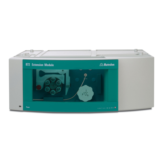
2 Overview of the instrument Front Sample Eluent Degasser Standard Eluent Figure 1 Front 872 Extension Module IC Module Standby indicator High pressure pump See Chapter 4.6 Coupling 6.2744.230 Purge valve For connecting the eluent aspiration tubing. See Chapter 4.6... -
Page 16: Rear
Vacuum Exhaust Transport locking screws Made by Metrohm Herisau Switzerland Figure 2 Rear 872 Extension Module IC Module Connector In Connector Out To connect the extension module to the IC To connect an additional extension module. instrument or to a previous extension mod- ule. -
Page 17: Assembly
(3-C) with a separate 6.2061.110 base tray and ■ a 6.2061.100 bottle holder (to be ordered additionally). For this, the longer 6.2156.070 connection cable (to be ordered additionally), is necessary, too. ■■■■■■■■ 872 Extension Module IC Module... -
Page 18: 3.2 Mounting The Extension Module Onto The Ic Instrument
2 Clearing the bottle holder If there are bottles and other items on the bottle holder, remove them. 3 Removing drainage tubings Loosen the drainage tubing from the drainage tubing connector on the bottle holder. ■■■■■■■■ 872 Extension Module IC Module... -
Page 19: Figure 4 Dismounting The Bottle Holder
Remove covering stoppers (4-1). ■ Loosen the cylinder screws with a 6.2621.100 3 mm hexagon ■ key. Remove the bottle holder ■ 5 Attaching the extension module(s) Place the extension module(s) on the IC instrument. ■■■■■■■■ 872 Extension Module IC Module... -
Page 20: Figure 5 Mounting The Bottle Holder
In of the second extension module and screw it tight. Plug the other end of the cable into the Out connector of the first ■ extension module and screw it tight. ■■■■■■■■ 872 Extension Module IC Module... -
Page 21: Mounting The Extension Module Below The Ic Instru- Ment
IC instrument (see manual for the IC instrument). 5 Removing the base tray Tilt the IC instrument sideways and lay it down flat. ■ Loosen the cylinder screws with a 6.2621.100 3 mm hexagon ■ key. Remove base tray. ■ ■■■■■■■■ 872 Extension Module IC Module... -
Page 22: Figure 6 Removing The Base Tray
Tilt the extension module sideways and lay it down flat. ■ Attach base tray. ■ Slide the washers onto the cylinder screws (7-2) and tighten these ■ with a 3 mm hexagon key (6.2621.100). ■■■■■■■■ 872 Extension Module IC Module... -
Page 23: Figure 7 Mounting The Base Tray
In of the second extension module and screw it tight. Plug the other end of the cable into the Out connector of the first ■ extension module and screw it tight. ■■■■■■■■ 872 Extension Module IC Module... -
Page 24: Setting Up The Extension Module Next To The Ic Instrument
2 Mounting the base tray Tilt the extension module sideways and lay it down flat. ■ Attach base tray. ■ Tighten the washers and the cylinder screws (8-2) with a 3 mm ■ hexagon key (6.2621.100). ■■■■■■■■ 872 Extension Module IC Module... -
Page 25: Figure 8 Mounting The Base Tray
■■■■■■■■■■■■■■■■■■■■■■ 3 Assembly Figure 8 Mounting the base tray Base tray Cylinder screws With washer. Set up the extension module. ■ Optional: Set up further extension modules. ■ ■■■■■■■■ 872 Extension Module IC Module... -
Page 26: Figure 9 Mounting The Bottle Holder
In of the second extension module and screw it tight. Plug the other end of the cable into the Out connector of the first ■ extension module and screw it tight. ■■■■■■■■ 872 Extension Module IC Module... -
Page 27: Figure 10 Connecting The Drainage Tubings
7 Connecting the drainage tubings Figure 10 Connecting the drainage tubings Drainage tubing connector Drainage tubing For draining escaped liquid from the bottle Section of the 6.1816.020 silicon tubing. For holder. draining escaped liquid from the bottle holder. ■■■■■■■■ 872 Extension Module IC Module... -
Page 28: Transport Locking Screws
Warning In order to avoid damage to the pump, the transport locking screws must be remounted each time the instrument undergoes major trans- port. ■■■■■■■■ 872 Extension Module IC Module... -
Page 29: Installation
The Installation chapter contains this overview ■ a brief set of instructions for the installation of the 872 Extension Mod- ■ ule IC Module (see Chapter 4.2, page 21). At each step you will find cross-references to more detailed installation instructions for individual components, should you require such aids. -
Page 30: Installation Diagram
■ 4.6.2, page 31). Installation diagram Figure 11 Installation diagram shows the capillary connections of the 872 Extension Module IC Module as an additional IC Module which can be integrated into any existing system. The arrangement of the modules in the diagram corresponds to the front view of the extension module. -
Page 31: Eluent
■ To equip the eluent aspiration tubing proceed as follows: Assembling eluent aspiration tubing 1 Guide the free end of the eluent aspiration tubing (12-1) out of the instrument through a suitable capillary feed-through. ■■■■■■■■ 872 Extension Module IC Module... -
Page 32: Figure 12 Installing Eluent Bottle Attachment
From accessories set 6.1602.160. 3 Mounting aspiration filter Insert filter holder (13-1) into the aspiration filter (13-2) and screw ■ tight. Figure 13 Mounting aspiration filter Filter holder Aspiration filter 6.2821.090 From accessories set 6.2744.210. ■■■■■■■■ 872 Extension Module IC Module... -
Page 33: Figure 14 Install Tubing Weighting And Aspiration Filter
Screw together clamping screw (14-4) and filter holder (13-1). ■ Figure 15 Eluent aspiration tubing fully equipped. 5 Mounting eluent aspiration tubing to the eluent bottle Insert the eluent aspiration tubing into the eluent bottle (16-10). ■ ■■■■■■■■ 872 Extension Module IC Module... -
Page 34: Figure 16 Eluent Bottle - Connected
Fasten the adsorber tube (16-2) using the SGJ clip (16-12) onto ■ the bottle attachment (16-11). Figure 16 Eluent bottle – connected Eluent aspiration tubing 6.1834.080 Adsorber tube 6.1609.000 For aspirating the eluent. Pre-installed. ■■■■■■■■ 872 Extension Module IC Module... -
Page 35: Eluent Degasser
Note The eluent degasser is already installed in the newly delivered instru- ment. The following installation instructions must only be followed, if the connections to the degasser had to be disconnected for mainte- nance. ■■■■■■■■ 872 Extension Module IC Module... -
Page 36: Figure 17 Eluent Degasser
Carefully tighten the clamping screw (17-4). ■ Connect the other end of the connection capillary (17-6) (with ■ the shorter clamping screw ) to the high pressure pump (18-9) (see "Connecting inlet to the high pressure pump", page 30). ■■■■■■■■ 872 Extension Module IC Module... -
Page 37: High Pressure Pump
Figure 18 Capillary connections high pressure pump/purge valve Connection capillary PEEK pressure screw, short 6.2744.070 PEEK capillary, connects main piston and auxiliary piston. Outlet valve holder Pump head 6.2824.110 ■■■■■■■■ 872 Extension Module IC Module... -
Page 38: Figure 19 High Pressure Pump - Connect Inlet
For connecting the coupling (19- ) to the (19- ) to the input of the high pressure pump head input capillary (18- pump. Can be ordered together with the coupling under the number 6.2744.230. ■■■■■■■■ 872 Extension Module IC Module... -
Page 39: Deaerating The High Pressure Pump
Deaerate the high pressure pump as follows (see Figure 20, page 32): Deaerating the high pressure pump The instrument must be connected to the PC and switched on to deaerate the high pressure pump. ■■■■■■■■ 872 Extension Module IC Module... -
Page 40: Figure 20 Deaerating The High Pressure Pump
4 Setting the flow rate Start MagIC Net (if not yet started). ■ Ensure that the eluent aspiration tubing is immersed sufficiently in ■ the eluent. Let the high pressure pump run. ■ ■■■■■■■■ 872 Extension Module IC Module... -
Page 41: Inline Filter
The following installation instructions need not be carried out at the time of initial installation. Installing the inline filter Caution Observe the flow direction marked on the filter housing for the connec- tion of the inline filter. ■■■■■■■■ 872 Extension Module IC Module... -
Page 42: Pulsation Damper
(see Chapter 4.6, page 29) and injection valve (see Chapter 4.9, page 35). The pulsation damper can be operated in both directions. ■■■■■■■■ 872 Extension Module IC Module... -
Page 43: Injection Valve
1 and 2), two for the eluent path (connectors 4 and 5) and two for the sample loop (connectors 3 and 6). Note The capillaries of the eluent path and the sample path and the sample loop are already installed in the newly delivered instrument. ■■■■■■■■ 872 Extension Module IC Module... -
Page 44: Figure 23 Injection Valve - Connected
Fasten one end of the sample loop (23-2) with a 6.2744.010 ■ PEEK pressure screw (23-7) to connector 3. Fasten the other end of the sample loop (23-2) with a second ■ 6.2744.010 PEEK pressure screw (23-7) to connector 6. ■■■■■■■■ 872 Extension Module IC Module... -
Page 45: Mode Of Operation Of The Injection Valve
The flow in the sample path is either stopped or the sample flows directly to the waste container. ■■■■■■■■ 872 Extension Module IC Module... -
Page 46: Selecting The Sample Loop
The choice is made on the basis of the application. The fol- lowing sample loops are normally used: Cation determination 10 µL Anion determination with suppression 20 µL Anion determination without suppression 100 µL ■■■■■■■■ 872 Extension Module IC Module... -
Page 47: Set To Work
Putting IC instrument into operation with extension mod- ules 1 Start MagIC Net. 2 Connect the 872 Extension Module to the 850 Professional IC. 3 Connect the 850 Professional IC instrument to the PC and switch on. The extension module is recognized automatically by MagIC Net. -
Page 48: Operation And Maintenance
Metrohm. If working frequently with caustic and corrosive chemicals, a shorter mainte- nance interval is recommended. The Metrohm service department offers every form of technical advice for maintenance and service of all Metrohm instruments. 6.1.3... -
Page 49: Shutting Down
The composition of the eluent has a crucial effect on the chromatographic analysis: Concentration An increase in the concentration generally leads to shorter retention times and faster separation, but also to higher background conductivity. ■■■■■■■■ 872 Extension Module IC Module... -
Page 50: Operation
To protect the high pressure pump against foreign particles, we recom- mend that the eluent undergoes a microfiltration (filter 0.45 µm) before being aspirated via a 6.2821.090 aspiration filter (see "Assembling eluent aspiration tubing", page 23). ■■■■■■■■ 872 Extension Module IC Module... -
Page 51: Maintenance
3 Unscrew the pump head output capillary (18-13) from the pump head. 4 Remove pump head from the pump housing by loosening the 4 fas- tening screws (18-5) using the 6.2621.030 hexagon key. The main ■■■■■■■■ 872 Extension Module IC Module... -
Page 52: Figure 25 Removing Piston
Loosen the screw of the piston cartridge with a wrench and ■ unscrew carefully by hand and by holding pressure towards the taut spring. Remove the zirconium oxide piston and lay on a tissue. ■ ■■■■■■■■ 872 Extension Module IC Module... -
Page 53: Figure 26 Components Of The Piston Cartridge
■ piston cartridge. Slide the zirconium oxide piston carefully into the piston cartridge ■ until its tip emerges from the small opening of the piston car- tridge. Attach screw and tighten by hand. ■ ■■■■■■■■ 872 Extension Module IC Module... -
Page 54: Figure 27 Tool For Piston Seal 6.2617.010
Avoid touching the sealing surface in the pump head (18-4) with the tool. Screw the special tool for the piston seal (27-1) with the narrow side just as far into the piston seal as the same can be removed. ■■■■■■■■ 872 Extension Module IC Module... -
Page 55: Figure 28 Removing The Piston Seal
Guide the sleeve of the tool for the piston seal (27-2) with inserted piston seal into the pump head and press the seal with the wide end of the tool for the piston seal (27-1) into the pump head recess. ■■■■■■■■ 872 Extension Module IC Module... -
Page 56: Figure 30 Inserting The Piston Seal Into The Pump Head
Cleaning the inlet valve and outlet valve 1 Removing valves Unscrew the connection capillary for the auxiliary piston (18-1) ■ from the outlet valve holder. Unscrew the holders for the inlet and outlet valves and remove ■ valves. ■■■■■■■■ 872 Extension Module IC Module... -
Page 57: Figure 31 Removing Valves
Only if this cleaning is useless, dismantle the valves separately and clean the components. 3 Dismantling valve Dismantle every valve separately. Note For dismantling the valve the 6.2617.020 tool for valve cartridges is required. ■■■■■■■■ 872 Extension Module IC Module... -
Page 58: Figure 32 Dismantling Valve
The components of the valve are very small. In order not to lose them, put the components into a dish. The inlet valve and the outlet valve consist of the same, just differ- ■ ently arranged components (see Figure 33, page 51). ■■■■■■■■ 872 Extension Module IC Module... -
Page 59: Figure 33 Components Of The Inlet Valve And Outlet Valve
Reassemble valve components according to figure 33, page 51. Insert the seal with the larger opening faced downwards into the ■ recess of the tool. Lay the other valve components above another in the correct ■ sequence (see Figure 33, page 51). ■■■■■■■■ 872 Extension Module IC Module... - Page 60 Insert the outlet valve into the outlet valve holder the way the seal ■ is visible. Screw the outlet valve holder into the top of the pump head and ■ tighten with a wrench (31-1). ■■■■■■■■ 872 Extension Module IC Module...
-
Page 61: Inline Filter
PEEK pressure screws, short Filter housing 6.2744.070 Housing of the inline filter. Part of the 6.2821.120 accessories. 6.2821.130 filter Filter screw Packaging contains 10 items. Screw of the inline filter. Part of the 6.2821.120 accessories. Connection capillaries ■■■■■■■■ 872 Extension Module IC Module... - Page 62 Screw the pressure screws (34-1) back onto the inline filter. ■ 6 Rinsing the inline filter Dismantle the guard column (if present) and the separation col- ■ umn and replace with a 6.2744.040 coupling. Rinse the instrument with eluent. ■ ■■■■■■■■ 872 Extension Module IC Module...
-
Page 63: Inline Sample Preparation
H ) and cation exchange (replacement of e.g. heavy metals with H ), a sample preparation module (SPM) is used. For an overview of all Metrohm inline sample preparation methods go to the following website:http://misp.metrohm.com Rinsing the sample path... - Page 64 A. The lower the ratio, the lower the sample carry-over. This ratio can be modified by varying the rinsing time – thus allowing the rinsing time required for the application to be ascertained. ■■■■■■■■ 872 Extension Module IC Module...
-
Page 65: Injection Valve
Metrohm» available from your local Metrohm agent. Validation Please contact your local Metrohm agent for support in validating instru- ments and software. Here you can also obtain validation documentation to provide help for carrying out the Installation Qualification (IQ) and the Operational Qualification (OQ). -
Page 66: Troubleshooting
6.2821.120 inline filter Replace 6.2821.130 filter (see Chapter 6.5, sure blocked. page 53). Injection valve – valve Have the valve cleaned (by Metrohm service blocked. technicians). Drift of the baseline Eluent – Evaporation of the Check the eluent bottle attachment (see Figure organic solvent in the elu- 14, page 25). - Page 67 Request Metrohm Service. tograms defective. Vacuum is not being Eluent Degasser – Connec- Seal the connector Vacuum tightly with a ■ built tor Vacuum on the rear of 6.1446.040 threaded stopper. the instrument not (tightly) sealed. ■■■■■■■■ 872 Extension Module IC Module...
-
Page 68: Technical Specifications
Painted polyurethane hard foam without CFCs, fire class V0 Material Intelligent com- MagIC Net ponents Ambient conditions Operation Ambient tem- +5…+45 °C perature Humidity 20…80 % relative humidity Storage Ambient tem- –20…+70 °C perature Transport Ambient tem- –40…+70 °C perature ■■■■■■■■ 872 Extension Module IC Module... -
Page 69: Housing
< 0.1 % deviation of the eluent flow Pressure range Pump 0…50.0 MPa (0…500 bar) Pump head 0…35.0 MPa (0…350 bar) (applies for the standard PEEK pump head) Residual pulsa- < 1 % tion ■■■■■■■■ 872 Extension Module IC Module... -
Page 70: Injection Valve
Material PEEK Interfaces Auxiliary 1 DSUB plug 15-pin (female) Analog Output Analog Output (optional) Safety specification Design / testing EN/IEC 61010-1 ■ UL 61010-1 ■ CSA-C22.2 No. 61010-1 ■ Protection class III ■ ■■■■■■■■ 872 Extension Module IC Module... -
Page 71: Electromagnetic Compatibility (Emc)
Electromagnetic compatibility (EMC) Emission EN/IEC 61326-1 ■ EN/IEC 61000-6-3 ■ EN 55011 / CISPR 11 ■ Immunity EN/IEC 61326-1 ■ EN/IEC 61000-6-1 ■ EN/IEC 61000-4-2 ■ EN/IEC 61000-4-3 ■ 8.11 Weight 1.872.0030 7.7 kg (without accessories) ■■■■■■■■ 872 Extension Module IC Module... -
Page 72: Conformity And Warranty
Name of commodity 872 Extension Module The 872 Extension Module is an expansion tool for upgrading all 850 Professional IC instruments. This instrument has been built and has undergone final type testing... -
Page 73: Quality Management Principles
Components All components used in the Metrohm instruments have to satisfy the qual- ity standards that are defined and implemented for our products. Suppli- ers of components are audited by Metrohm as the need arises. -
Page 74: Warranty (Guarantee)
System Validation for the quantitative determi- nation of a substance in a given matrix. Warranty (Guarantee) Metrohm guarantees that the deliveries and services it provides are free of errors in materials, design or manufacturing. The general warranty period is 36 months (exclusions below) from the date of delivery or 18 months in the event of continuous operation. - Page 75 Metrohm, such as improper storage or improper use, etc. are expressly excluded from the warranty. Metrohm also offers a 120-month spare parts warranty and a 5-year PC software support warranty, calculated from the date on which the prod- uct is withdrawn from the market. The content of this warranty is the abil- ity of the customer to obtain functioning spare parts or appropriate soft- ware support at market prices during the time of the warranty period.
-
Page 76: 10 Accessories
■■■■■■■■■■■■■■■■■■■■■■ 10.1 Scope of delivery 10 Accessories Note Subject to change without notice. 10.1 Scope of delivery 2.872.0030 872 Extension Module – IC Module Qty. Order no. Description 1.872.0030 872 Extension Module – IC Module 6.1602.160 Eluent bottle attachment GL 45 For eluent bottles;... - Page 77 PTFE Outer diameter (inches): 1/16 Inner diameter (mm): Length (m): 6.1825.230 PEEK sample loop 10 µL For injection valve, with 2 PEEK pressure screws Material: PEEK (metal-free) Outer diameter (inches): 1/16 Volume (mL): 0.01 ■■■■■■■■ 872 Extension Module IC Module...
- Page 78 Length (m): 6.2023.020 Clip for SGJ 14/15 Clip for SGJ 14/16 Material: 6.2156.060 Cable Extension Module - Professional IC, 40 cm Cable connecting the extension module with a Professional IC instru- ment Length (m): ■■■■■■■■ 872 Extension Module IC Module...
- Page 79 For removing and assembling the piston seal for all standard pump heads 6.2621.000 Adjustable wrench Max. opening: 20 mm. For IC instruments Length (mm): 6.2621.030 Hexagon key 4 mm Length (mm): 6.2621.050 1/4 in. wrench For 1/4 in. screws. For IC instruments Length (mm): ■■■■■■■■ 872 Extension Module IC Module...
- Page 80 Hexagon key 3 mm for IC Sample Processors Length (mm): 6.2739.000 Wrench For tightening connectors Length (mm): 6.2744.010 Pressure screw 5x With UNF 10/32 connection. For the connection of PEEK capillaries Material: PEEK Length (mm): ■■■■■■■■ 872 Extension Module IC Module...
- Page 81 Short version. With UNF 10/32 connection. 5 pieces. For the connec- tion of PEEK capillaries Material: PEEK Length (mm): 6.2744.120 Coupling pressure screw / Luer-F Connection pressure screw and syringe. Material: PEEK 6.2744.210 Tubing adaptor for aspiration filter (ProfIC) For Professional IC instruments ■■■■■■■■ 872 Extension Module IC Module...
- Page 82 6.1821.040 and 6.1821.050 Filter tubes. Material: Outer diameter (mm): Length (mm): 35.5 6.2821.130 Spare filter for inline filter Spare filters for inline filter. 8.872.8004EN Manual for 872 Extension Module, 2.872.0030 IC Module, English ■■■■■■■■ 872 Extension Module IC Module...
-
Page 83: Index
Eluent bottle ....... 23 Eluent bottle Regeneration ......40 Eluent degasser ....27 Figure ......... 26 Rinsing High pressure pump ... 29 Installation ......23 Sample path ....... 55 Injection valve ....35, 62 ■■■■■■■■ 872 Extension Module IC Module... - Page 84 High pressure pump ... 61 Sample path Reference conditions ..60 Warranty ........66 Rinsing ....... 55 Temperature ......60 Sample preparation ....55 Transfer time ......55 Scope of delivery ...... 68 Transport ......... 60 ■■■■■■■■ 872 Extension Module IC Module...
Need help?
Do you have a question about the 872 and is the answer not in the manual?
Questions and answers