Table of Contents
Advertisement
Quick Links
Advertisement
Table of Contents

Related Manuals for Metrohm 872


Summary of Contents for Metrohm 872
- Page 1 872 Extension Module Liquid handling – 2.872.0060 Manual 8.872.8003EN...
- Page 3 Metrohm AG CH-9101 Herisau Switzerland Phone +41 71 353 85 85 Fax +41 71 353 89 01 info@metrohm.com www.metrohm.com 872 Extension Module Liquid handling – 2.872.0060 Manual 8.872.8003EN 06. 2009 zst...
- Page 4 Teachware Metrohm AG CH-9101 Herisau teachware@metrohm.com This documentation is protected by copyright. All rights reserved. Although all the information given in this documentation has been checked with great care, errors cannot be entirely excluded. Should you notice any mistakes please send us your comments using the address...
-
Page 5: Table Of Contents
Setting up the extension module next to the IC instru- ment ..................19 Mounting the accessories ..........23 5 Installation About this chapter .............. 26 Installation overview ............26 Installation diagram ............27 ■■■■■■■■ 872 Extension Module – Liquid handling... - Page 6 Door ..................39 Peristaltic pump ..............39 7.3.1 Operation ................39 7.3.2 Maintenance ................. 40 Quality Management and validation with Metrohm ..42 8 Troubleshooting Problems and their solutions ..........43 9 Technical specifications Reference conditions ............44 Instrument ................44 Ambient conditions ............
- Page 7 ■■■■■■■■■■■■■■■■■■■■■■ Table of contents 10.2 Quality Management Principles ........48 10.3 Warranty (guarantee) ............49 11 Accessories 11.1 Scope of delivery ..............50 11.2 Optional accessories ............53 Index ■■■■■■■■ 872 Extension Module – Liquid handling...
- Page 8 ■■■■■■■■■■■■■■■■■■■■■■ Table of figures Table of figures Figure 1 Front 872 Extension Module – Liquid handling ........5 Figure 2 Rear 872 Extension Module – Liquid handling ........5 Figure 3 10-port valve – positions ..............6 Figure 4 Valve switchover, normal and with secured position ......7 Figure 5 6.1562.160 transfer tubing ...............
-
Page 9: Introduction
Every 850 Professional IC instrument can be supplemented with up to 3 extension modules. The 872 Extension Module – Liquid handling extends the possibilities of inline sample preparation and liquid handling. Up to six auxiliary solu- tions can be provided in the instrument. -
Page 10: Intended Use
■■■■■■■■■■■■■■■■■■■■■■ 1.2 Intended use Intended use With the 872 Extension Module – Liquid handling, an 850 Profes- sional IC instrument can be extended to include a broad range of addi- tional sample preparation possibilities without having to modify the instru- ment in between. -
Page 11: Safety Instructions
The electrical safety when working with the instrument is ensured as part of the international standard IEC 61010. WARNING Only personnel qualified by Metrohm are authorized to carry out service work on electronic components. ■■■■■■■■ 872 Extension Module – Liquid handling... -
Page 12: Tubing And Capillary Connections
The correct disposal of your old equipment will help to prevent negative effects on the environment and public health. More details about the disposal of your old equipment can be obtained from your local authorities, from waste disposal companies or from your local dealer. ■■■■■■■■ 872 Extension Module – Liquid handling... -
Page 13: Overview Of The Instrument
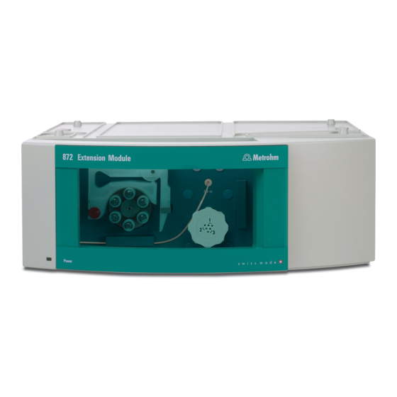
■■■■■■■■■■■■■■■■■■■■■■ 2 Overview of the instrument 2 Overview of the instrument Front Figure 1 Front 872 Extension Module – Liquid handling Standby indicator Peristaltic pump 10-port valve Injection valve Rear Made by Metrohm Herisau Switzerland Figure 2 Rear 872 Extension Module – Liquid handling... -
Page 14: Functioning
Connector for the connection to an auxiliary Connector for the connection to e.g. the solution. waste container. Position 9 10 Position 10 Connector for the connection to an auxiliary Connector for the connection to e.g. the ion solution. exchanger. ■■■■■■■■ 872 Extension Module – Liquid handling... -
Page 15: Figure 4 Valve Switchover, Normal And With Secured Position
4 is defined as the secured position, then the 10-port valve will automatically switch via the connectors 1 – 10 – 9 – 8 – 7 – 6 (see illustration 4, left). Figure 4 Valve switchover, normal and with secured position ■■■■■■■■ 872 Extension Module – Liquid handling... -
Page 16: Transfer Tubing
10-port valve through the central position and into the transfer tubing. During ejection, the liquid that has collected in the transfer tubing is ■ transported through the central position of the 10-port valve and from there to the active position. ■■■■■■■■ 872 Extension Module – Liquid handling... -
Page 17: Mixing Vessel
Connector For the 10-port valve. Like the other Metrohm sample vessels, the mixing vessel is made of poly- propylene PP. It has an extremely smooth surface which permits no drop formation. The mixing vessel can be readily rinsed out and dried. It can be used for anions as well as for cations. -
Page 18: Peristaltic Pump And Injection Valve
Following the switchover of the valve (8-2), the measured sample seg- ment (8-5) is conveyed by aspiration with the Dosino (8-1) through the 10-port valve (8-4) into the transfer tubing (8-6), from where it can be conveyed onward to a different outlet. ■■■■■■■■ 872 Extension Module – Liquid handling... -
Page 19: Figure 8 Measuring Volume - Aspirating Sample Segment
■■■■■■■■■■■■■■■■■■■■■■ 3 Functioning Figure 8 Measuring volume – Aspirating sample segment Dosino Injection valve Container with transfer solution 10-port valve Sample Transfer tubing ■■■■■■■■ 872 Extension Module – Liquid handling... -
Page 20: Assembly
(9-C) with a separate 6.2061.110 base tray and ■ a 6.2061.100 bottle holder (to be ordered additionally). For this, the longer 6.2156.070 connection cable (to be ordered additionally), is necessary, too. ■■■■■■■■ 872 Extension Module – Liquid handling... -
Page 21: Mounting The Extension Module Onto The Ic Instru- Ment
2 Clearing the bottle holder If there are bottles and other items on the bottle holder, remove them. 3 Removing drainage tubings Loosen the drainage tubing from the drainage tubing connector on the bottle holder. ■■■■■■■■ 872 Extension Module – Liquid handling... -
Page 22: Figure 10 Dismounting The Bottle Holder
Remove covering stoppers (10-1). ■ Loosen the cylinder screws with a 6.2621.100 3 mm hexagon ■ key. Remove the bottle holder ■ 5 Attaching the extension module(s) Place the extension module(s) on the IC instrument. ■■■■■■■■ 872 Extension Module – Liquid handling... -
Page 23: Figure 11 Mounting The Bottle Holder
In of the second extension module and screw it tight. Plug the other end of the cable into the Out connector of the first ■ extension module and screw it tight. ■■■■■■■■ 872 Extension Module – Liquid handling... -
Page 24: Mounting The Extension Module Below The Ic Instru- Ment
IC instrument (see manual for the IC instrument). 5 Removing the base tray Tilt the IC instrument sideways and lay it down flat. ■ Loosen the cylinder screws with a 6.2621.100 3 mm hexagon ■ key. Remove base tray. ■ ■■■■■■■■ 872 Extension Module – Liquid handling... -
Page 25: Figure 12 Removing The Base Tray
Tilt the extension module sideways and lay it down flat. ■ Attach base tray. ■ Slide the washers onto the cylinder screws (13-2) and tighten ■ these with a 3 mm hexagon key (6.2621.100). ■■■■■■■■ 872 Extension Module – Liquid handling... -
Page 26: Figure 13 Mounting The Base Tray
In of the second extension module and screw it tight. Plug the other end of the cable into the Out connector of the first ■ extension module and screw it tight. ■■■■■■■■ 872 Extension Module – Liquid handling... -
Page 27: Setting Up The Extension Module Next To The Ic Instrument
2 Mounting the base tray Tilt the extension module sideways and lay it down flat. ■ Attach base tray. ■ Tighten the washers and the cylinder screws (14-2) with a 3 mm ■ hexagon key (6.2621.100). ■■■■■■■■ 872 Extension Module – Liquid handling... -
Page 28: Figure 14 Mounting The Base Tray
4.4 Setting up the extension module next to the IC instrument Figure 14 Mounting the base tray Base tray Cylinder screws With washer. Set up the extension module. ■ Optional: Set up further extension modules. ■ ■■■■■■■■ 872 Extension Module – Liquid handling... -
Page 29: Figure 15 Mounting The Bottle Holder
In of the second extension module and screw it tight. Plug the other end of the cable into the Out connector of the first ■ extension module and screw it tight. ■■■■■■■■ 872 Extension Module – Liquid handling... -
Page 30: Figure 16 Connecting The Drainage Tubings
Figure 16 Connecting the drainage tubings Drainage tubing connector Drainage tubing For draining escaped liquid from the bottle Section of the 6.1816.020 silicon tubing. For holder. draining escaped liquid from the bottle holder. ■■■■■■■■ 872 Extension Module – Liquid handling... -
Page 31: Mounting The Accessories
(16-4) and guide the other end into a waste container. Mounting the accessories The bottle holder for the 872 Extension Module – Liquid handling 6.2057.200 can be mounted on the instrument in order to set up the dif- ferent small bottles, the mixing vessel and the transfer tubing in proper sequence in front of the instrument. - Page 32 Hang up the bottle holder (1) and slide it downwards (2) 4 Equipping the bottle holder Place the transfer tubing, the mixing vessel and PE bottles in the recesses of the bottle holder. ■■■■■■■■ 872 Extension Module – Liquid handling...
- Page 33 ■■■■■■■■■■■■■■■■■■■■■■ 4 Assembly 6.1562.160 transfer tubing 6.2057.200 bottle holder 6.1608.100 PE bottle 6.2762.000 mixing vessel 50mL content. 50 mL content, with 6.2762.010 cover. ■■■■■■■■ 872 Extension Module – Liquid handling...
-
Page 34: Installation
IC instrument ■ and extension module. a brief set of instructions for the installation of the 872 Extension Mod- ■ ule Liquid handling (see Chapter 5.2, page 26). At each step you will find cross-references to more detailed installation instructions for indi- vidual components, should you require such aids. -
Page 35: Installation Diagram
■■■■■■■■■■■■■■■■■■■■■■ 5 Installation Installation diagram The peristaltic pump, the injection valve and the 10-port valve of the 872 Extension Module – Liquid handling can be installed in different ways, depending on the application. The installation illustrated in the following shows only one out of many possible installations. -
Page 36: 10-Port Valve
Connection to the injection valve in the extension module. ■ Connection to the injection valve in the IC instrument. ■ Connection to the mixing vessel. ■ Connection to different solutions. ■ Connection to an ion exchanger. ■ etc. ■ ■■■■■■■■ 872 Extension Module – Liquid handling... -
Page 37: Peristaltic Pump
(18-2), so that the rollers (18-3) push the liquid for- ward in the pump tubing. Figure 18 Peristaltic pump Knurled screw in the mounting pin Roller hub Rollers Cartridge holder Tubing cartridges 6.2755.000 Contact pressure lever Snap-action lever ■■■■■■■■ 872 Extension Module – Liquid handling... -
Page 38: Installing The Peristaltic Pump
Release the tubing cartridge from the cartridge holder by pressing the snap-action lever and unhooking from the mounting pins (18-1). 2 Connecting the aspiration side Place a 6.2744.034 tubing olive (19-2) on the aspiration side of the pump tubing. ■■■■■■■■ 872 Extension Module – Liquid handling... -
Page 39: Figure 20 Install Pump Tubing Connection With Filter
Place the tubing olive with filter holder (20-3) onto the pump tub- ■ ing. Screw the union nut (20-1) onto the tubing olive (20-3). ■ Case B: 6.2744.160 pump tubing connection without filter: ■■■■■■■■ 872 Extension Module – Liquid handling... -
Page 40: Figure 21 Install Pump Tubing Connection Without Filter
Screw the respective capillaries tightly to the two tubing olives ■ with PEEK pressure screws (19-1). Table 1 Pump tubings and suitable adapters Pump tubing Adapter 6.1826.020 (blue/blue) 6.1826.310 (orange/green) 6.1826.320 (orange/yellow) 6.1826.330 (orange/white) ■■■■■■■■ 872 Extension Module – Liquid handling... - Page 41 NOTE Pump tubings are consumable material. The service life of the pump tubings depends on the contact pressure amongst other factors. ■■■■■■■■ 872 Extension Module – Liquid handling...
-
Page 42: Injection Valve
Transfer solution outlet capillary Transfer solution aspirating capillary to the 10-port valve. to the container with transfer solution. Sample outlet capillary Sample inlet capillary to the waste container. from the peristaltic pump PEEK pressure screw 6.2744.010 ■■■■■■■■ 872 Extension Module – Liquid handling... -
Page 43: Mode Of Operation Of The Injection Valve
The following figure provides a schematic dis- play of the flow paths of the two valve positions. Figure 23 Injection valve – Positions Position FILL Position INJECT Transfer solution outlet Transfer solution inlet ■■■■■■■■ 872 Extension Module – Liquid handling... - Page 44 10- port valve to the transfer tubing. ■■■■■■■■ 872 Extension Module – Liquid handling...
-
Page 45: Start-Up
The extension module is recognized automatically by MagIC Net. Additional information can be found in the Start-up chapter in the manual for the IC instrument as well as in the MagIC Net online Help. ■■■■■■■■ 872 Extension Module – Liquid handling... -
Page 46: Operation And Maintenance
In such cases, the Metrohm Service must be informed. Spillages of chemicals and solvents should be cleaned up immediately. In particular, the plug connections on the rear panel of the instrument (espe- cially the mains plug) should be protected from contamination. -
Page 47: Shutting Down
Therefore fully lift the tubing cartridges by loosening the snap- action lever (19-10) on the right-hand side if the peristaltic pump is to be turned off for a longer period. Once set, the contact pressure remains unaffected. ■■■■■■■■ 872 Extension Module – Liquid handling... -
Page 48: Maintenance
Pump tubing for bromate (orange/green), 3- determination using the stopper triiodide method. 6.1826.320 Pump tubing LFL PVC (Tygon) 0.48 mm For suppressor solutions, (orange/yellow), 3- acceptor solutions for stopper inline dialysis and for inline ultrafiltration. ■■■■■■■■ 872 Extension Module – Liquid handling... -
Page 49: Figure 24 Pump Tubing Connection - Changing The Filter
6.2621.000 adjustable wrenches. 2 Replacing the filter Remove the old filter (24-2) with tweezers. ■ Place the new filter (24-2) flat in the tubing olive (24-1) with ■ tweezers. ■■■■■■■■ 872 Extension Module – Liquid handling... -
Page 50: Quality Management And Validation With Metrohm
Metrohm» available from your local Metrohm agent. Validation Please contact your local Metrohm agent for support in validating instru- ments and software. Here you can also obtain validation documentation to provide help for carrying out the Installation Qualification (IQ) and the Operational Qualification (OQ). -
Page 51: Troubleshooting
33). delivery rate Peristaltic pump – filter Replace the filter (see Chapter 7.3.2.2, page blocked. 41). Peristaltic pump – pump Replace pump tubing (see Chapter 7.3.2.1, tubing defective. page 40). ■■■■■■■■ 872 Extension Module – Liquid handling... -
Page 52: Technical Specifications
Painted polyurethane hard foam without CFCs, fire class V0 Material Intelligent com- MagIC Net ponents Ambient conditions Operation Ambient tem- +5…+45 °C perature Humidity 20…80 % relative humidity Storage Ambient tem- –20…+70 °C perature Transport Ambient tem- –40…+70 °C perature ■■■■■■■■ 872 Extension Module – Liquid handling... -
Page 53: Housing
Counterclockwise/Clockwise rotation Rotational speed 0…42 rpm in 7 stages at 6 rpm. Pumping proper- 0.3 mL/min at 18 rpm; with 6.1826.320 standard pump tubing. ties Material of pump recommended: Tygon Long Flex Life tubings ■■■■■■■■ 872 Extension Module – Liquid handling... -
Page 54: Injection Valve
Emission EN/IEC 61326-1 ■ EN/IEC 61000-6-3 ■ EN 55011 / CISPR 11 ■ Immunity EN/IEC 61326-1 ■ EN/IEC 61000-6-1 ■ EN/IEC 61000-4-2 ■ EN/IEC 61000-4-3 ■ 9.11 Weight 1.872.0060 7.7 kg (without accessories) ■■■■■■■■ 872 Extension Module – Liquid handling... -
Page 55: Conformity And Warranty
Name of commodity 872 Extension Module The 872 Extension Module is an expansion tool for upgrading all 850 Professional IC instruments. This instrument has been built and has undergone final type testing... -
Page 56: Quality Management Principles
Components All components used in the Metrohm instruments have to satisfy the qual- ity standards that are defined and implemented for our products. Suppli- ers of components are audited by Metrohm as the need arises. -
Page 57: Warranty (Guarantee)
10.3 Warranty (guarantee) Metrohm guarantees that the deliveries and services it provides are free from material, design or manufacturing errors. The warranty period is 36 months from the day of delivery; for day and night operation it is 18 months. -
Page 58: Accessories
■■■■■■■■■■■■■■■■■■■■■■ 11.1 Scope of delivery 11 Accessories NOTE Subject to change without notice. 11.1 Scope of delivery 2.872.0060 872 Extension Module – Liquid handling Qty. Order no. Description 1.872.0060 872 Extension Module – Liquid handling 6.1562.160 Transfer tubing 15 mL, 2 x M6 For liquid handling in ion chromatography. - Page 59 0.25 Length (m): 6.2057.200 Bottle holder to Extension Module - Liquid Handling 6.2156.060 Cable Extension Module - Professional IC, 40 cm Cable connecting the extension module with the Professional IC instrument Length (m): ■■■■■■■■ 872 Extension Module – Liquid handling...
- Page 60 PEEK capillaries Material: PEEK Length (mm): 6.2744.090 Pressure screw long Long version. With UNF 10/32 connection. 2 pieces. For the connec- tion of PEEK capillaries (MCS and Sample degasser) Material: PEEK ■■■■■■■■ 872 Extension Module – Liquid handling...
-
Page 61: Optional Accessories
Mixing vessel 50 mL to Extension Module - Liquid Handling 6.2762.010 Cover to mixing vessel 6.2762.000 11.2 Optional accessories 2.872.0060 872 Extension Module – Liquid handling Order no. Description 6.2061.100 Bottle holder (ProfIC) Bottle holder to Professional IC instruments ■■■■■■■■... - Page 62 Adaptor to connect two leak sensors to one Professional IC instrument 6.2156.070 Cable Extension Module - Professional IC, 1 m Cable connecting the extension module with the Professional IC instrument Length (m): 6.5332.000 IC tubing kit for second extension module ■■■■■■■■ 872 Extension Module – Liquid handling...
- Page 63 ■■■■■■■■■■■■■■■■■■■■■■ 11 Accessories Order no. Description 6.9988.503 Validation Documentation for 850 (English / German) – CD ■■■■■■■■ 872 Extension Module – Liquid handling...
-
Page 64: Index
Pump tubings Inject see also "10-port valve" ..28 Installing ......30 Injection valve ....36 Service life ......39 Injection valve ......1 Fill ........36 Warranty ........49 Inject ........36 ■■■■■■■■ 872 Extension Module – Liquid handling...
Need help?
Do you have a question about the 872 and is the answer not in the manual?
Questions and answers