Advertisement
Quick Links
+050001462 - rel. 1.7 - 30.07.2018
zz
V-Z - 電子膨張弁 / Electronic expansion valve
E
2
JPN
コード
説明
サイトグラス付き
E2V**Z**A*
サイトグラス無し
E2V**Z**B*
シングル梱包
E2V**Z***0
マルチ梱包
E2V**Z***1
E2VSTA***0: シングル梱包
E2VSTA***1: マルチ梱包
取付位置 / Positioning
コンプレッサ
Compressor
凝縮器
Condenser
電子膨張弁 E
V
2
E
V expansion valve
2
OK
ろう付けと取扱注意 / Welding and handling
T. Max
650°C
PTFE 製
ガスケット
フィルター
オーリング
Max 20Nm
A
B
C
重要な警告
JPN
CAREL製品は最先端の製品であり、その動作は製品に付属の技術文書で指定されているか、購入前であってもWebサイトwww.carel.com
からダウンロードできます。 クライアント(最終機器の製造業者、開発者または設置業者)は、特定の最終設置および/または機器に
関して期待される結果に達するために、製品の構成段階に関するすべての責任とリスクを負います。 ユーザーマニュアルに要求され
ている/示されているそのような研究段階の欠如は、最終製品に誤動作を引き起こし、その結果、CARELは責任を負いかねます。
クライアントは、製品自体に関連する文書に記載されている方法でのみ製品を使用しなければなりません。 CARELの自社製品に対する
責任は、Webサイトwww.carel.comで編集されたCARELの一般契約条件および/または顧客との特定の契約によって規定されています。
物や人への損害を避けるためにこれらの指示を注意深く読んでください。 詳細については、本製品をイン
ストールする前に、「EEVシステムズオペレーティングマニュアル(コード+030220811)」をお読みくだ
JPN
さい。 このマニュアルは、www.carel.comの「ドキュメント」ダウンロードエリアにあります。
概要説明
E2V-Z型電子膨張弁は、冷媒膨張装置として冷媒回路に設置するように設計されており、蒸発器の出口に取付けた圧
力プローブと温度プローブによって計算された過熱度を制御信号として使用します。入口部の流体は、バルブがフ
ラッシュガスで作動するのを防ぐために適切な過冷却が必要です。 冷媒チャージが不十分であるか、またはバルブ
の下流で著しい圧力降下があると、バルブノイズが増加する可能性があります。 E2V-Zの制御にはCAREL製のコント
Code
Description
ローラのみを使用してください。下記に示す通常の操作条件以外では、E2V-Zバルブを使用しないでください。
E2V**Z**A*
valve with sight glass
E2V**Z**B*
valve without sight glass
取付位置
E2V**Z***0
single package
E2V-Zバルブは両流れ式です。 側面の接続部を液冷媒の優先注入口として使用します(図1)。これにより、停電時
E2V**Z***1
multi-package
にディスクをシートに押し込む圧力でバルブを閉弁状態にキープするのを補助してくれます。膨張弁の前に遮断弁
E2VSTA***0: single package
を使用する場合は、弁の近くに液ハンマーが発生しないように回路を設定する必要があります。 回路内の危険な過
E2VSTA***1: multi-package
剰圧力を回避するために、シャットオフバルブと膨張弁を同時に閉じることは絶対にしないでください。
冷膨張弁の上流には必ず機械式フィルタを取り付けてください。
ステーターが下を向いていてはならない(バルブが上下逆になっている)ことを除けば、バルブはどの方向にも向
けることができます。
E2V-Zバルブの推奨取付け位置は、従来の温度式膨張弁と同じ、つまり蒸発器とディストリビュータの上流です。
温度センサと圧力センサ(E2V-Zには付属していません)は、蒸発器のすぐ下流に取付ける必要があります。
• 温度センサは導電性ペーストを使用して吸入管に取付け、外部から十分に断熱処理をします。
過熱度測定
• 両方のセンサは、圧力(例えば弁)および/または温度を変える装置(例えば熱交換器)の上流側に設置する必要
Superheating detection
があります。
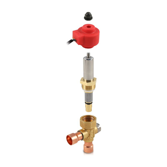
ろう付けと取扱注意
E2V-Zバルブは、銅製継手を凝縮器出口(IN)および蒸発器入口(OUT)の配管にろう付け溶接することによって回
蒸発器
路に取付けます。 図2のように進めます。
包装からバルブの本体を取り出します。
Evaporator
1.
継手の配管挿入停止位置を超えないように注意しながら、パイプを雌継手に挿入します。 図2-Aに示すように継
2.
手の端に火炎を向けてろう付けします(本体と継手の間の溶接部のシールに影響を与えずにろう付け溶接を改善
するには、溶融温度が650°C未満の合金を使用する。 または25%を超える銀含有量のろう材を使用します。
カートリッジを箱から取り出します。
3.
4.
PTFEとOリングが取り付けられていることを確認してください(図2)。
金属製メッシュフィルターが真鍮製ブッシュに挿入されていることを確認してください(図2)。 それ以外の場
5.
合は、図のように配置して、正しく配置されていることを確認します。
警告! 当該フィルターは、入口側からの流体に対して効果的です。 逆方向に使用する場合は、付属のフィル
ターを外して回路内に専用のフィルタ(バイフローフィルタードライヤ等)を取り付けてください。
カートリッジ用オーリングの外面をオイル(冷媒回路で通常使用されるもののいずれか)で潤滑する必要があり
6.
ます(図2)。
カートリッジを挿入時に無理に押し込まないように注意しながら、ろう付け本体の内側に挿入します(図2)。
7.
限界に達するまで真鍮ナットを手でねじ込みます(図2)。
8.
バルブ本体のナットを24インチのフォークレンチで45Nmの締め付けトルクで締め付けます(図2)。 既存の
9.
カートリッジを別のサイズに交換するだけで(バルブ本体を変更せずに)バルブサイズを変更することができま
す。
別売の赤い固定子(「電気接続」を参照)を固定子のゴムリングが変形するまで黒いナットをしっかりと締め付
10.
けてカートリッジに挿入します(締め付けトルク0.3 Nm)(図2)。
モーター(ステーター)に配線済みでない場合は、互換性のあるケーブルでモーターをドライバーに接続します。
11.
(「電気接続」参照)
Carel製のドライバで駆動する場合に限り、CarelはCarel製 ExVシステムの正しい動作を保証します。 Carelと明示的に
OK
NO
合意のない場合、他の製造元のドライバでCarel ExVsシステムを使用すると、自動的に保証が無効になります。
Fig.1
重要:CAREL製バルブは全開位置で供給されます。 回路に溶接する前にバルブを作動させた場合、ろう付け時の
高温によって内部部品が損傷するのを防ぐため、バルブを全開位置に戻す必要があります。
注:
• バルブや接続パイプをねじったり、ひねったりしないでください。
• ハンマーなどでバルブを叩かないでください。
• ペンチやその他の工具を使用して外部構造を変形させたり、内部部品を損傷させたりしないでください。
0,3 Nm
• 火炎を絶対にバルブ側に向けないでください。
• バルブを磁石や磁界の近くに置かないでください。
• 次のような場合には、バルブを取り付けたり使用したりしないでください。変形や外部構造の損傷。 落下などに
よる大きな損傷。 電気部品(ステータ、コンタクトキャリア、コネクタなど)の損傷。
• CARELは、外部構造の変形や電気部品の損傷が発生した場合のバルブの動作を保証するものではありません。
• ゴミの混入はバルブの故障の原因となります。
• カートリッジやサイトグラスを取り外した後は、OリングをCarel純正スペアパーツと交換してください。
40-45Nm
電気接続
ステーターにケーブルが付いていない場合は、適合ケーブルをモーターに接続します。
ポーラモーターの場合は、E2VCAB****を使用してください。:マッピングは1に緑、2に黄色、3に茶色、4に白です。
D
E
重要:フェーズ4はバルブのステータにアース記号で表示されています。 2004/108 / EC指令およびそれに続く修正
に準拠した用途には、オプションのシールドケーブル(E2VCABS ***)が利用可能です。
CAREL E
V-Zの動作仕様
2
適合性
最高使用圧力(MOP、PS)
本体許容最大圧力 UL / CSA(MBP)
Fig. 2
バルブの設計圧力
IN / OUT最大差圧
P.E.D.
UL / CSA認証(電気作動弁のUL 429および
CSA C 22.2 no.139-2010規格):
冷媒温度
最終
周囲温度
全閉ステップ数
制御ステップ数
その他の通常の運転条件や冷媒については、CARELにお問い合わせください。
ケーブルが内蔵されたバイ
グループ1: R1234yf, R32, R290, R600, R600a - グループ2: R22, R134a, R404A, R407C, R410A,
R744, R507A, R417A, R1234ze, R448A, R449A, R450A, R513A
60 barg (870 psig)
45 bar (653 psi)
60 barg (870 psig);E2V ** Z ** B *バージョンの場合のみ:サイド継手を入口と
して使用のバルブが閉弁状態で制御状態でないとき 90 barg(1305 psig)
35 bar(508 psi) - バイポーラおよびユニポーラステーター使用時 -
26 bar(377 psi)ユニポーラステーター使用のE2V35Z ****のみ
Groups 1 and 2, Art. 4, par. 3
A1クラス冷媒のみを対象としてULファイル番号E304579
-40T70°C(-40T158°F)
-30T70°C(-22T158°F)
500
480
Carefully read these instructions to avoid damage to objects or people. For more information, read the "EEV systems
operating manual (code +030220811) before installing this product. The manual is available in the "documentation"
download area at www.carel.com.
General features
The E
2
V-Z electronic valve is designed for installation in refrigerant circuits as the refrigerant expansion device, using the superheat
calculated by a pressure and temperature probe located at the evaporator outlet as the control signal. The inlet fluid should be sui-
tably subcooled to prevent the valve from operating with flash gas. Valve noise may increase when refrigerant charge is insufficient
or there is significant pressure drop downstream of the valve. Only CAREL instruments should be used for the control of the E
Do not use the E2V-Z valves outside of the normal operating conditions, shown below.
Positioning
The E
2
V-Z valves are double-acting. Use the side connection as the preferential inlet for the liquid (Fig. 1 ), as this helps the valve remain
closed in the event of power failures, due to the pressure that pushes the disc into the seat. If using shutoff valves before the expansion
valve, the circuit must be set up so that no fluid hammer is created near the valve. The shutoff valve and expansion valve must never
be closed at the same time, to avoid dangerous excess pressure in the circuit.
Always install a mechanical filter upstream of the refrigerant inlet.
The valve can be oriented in any direction, with the exception that the stator must not be pointed downwards (valve upside down) .
The recommended position for the E
2
V-Z valve is the same as for traditional thermostatic valves, that is, upstream of the evaporator and
any distributors.
The temperature and pressure sensors (not supplied with the E
2
V-Z ) must be positioned immediately downstream of the evaporator,
making sure that:
• the temperature sensor is installed using conductive paste and is adequately thermally insulated from the outside;
• both the sensors are installed BEFORE any devices that vary the pressure (e.g. valves) and/or temperature (e.g. exchangers).
Welding and handling
The E2V-Z valves must be joined to the circuit by braze welding the copper fittings to the condenser outlet (IN) and evaporator inlet
(OUT) pipes. Proceed as indicated in Fig. 2:
1.
take the body of the valve from the packaging.
2.
Insert the pipes in the female valve fittings, being careful not to go beyond the specific restrictions present in the joints of the
valve. Weld by aiming the flame at the ends of the fittings as shown in Fig. 2-A (for better braze welding without affecting the seal
of the welded area between the body and the fittings, use alloys with a fusion temperature less than 650 °C or with a silver content
above 25%);
3.
Take the cartridge.
4.
Make sure that the PTFE and l'oring are present and positioned in their site (Fig. 2-B).
5.
Make sure that the metal mesh filter is inserted on the brass bushing (Fig.2-B). Otherwise, position it as shown in the figure
and make sure it's properly in place.
Warning! The filter is efficacious with fluid inlet from the connection side. If using the valve in the opposite direction,
install a special filter in the circuit, removing the one supplied.
It is necessary to lubricate with oil (any of those normally used in refrigerant circuits) the outer surface of the cartridge
6.
oring (Fig. 2-B)
7.
Insert the cartridge inside the braided body, taking care not to force it during insertion (Fig 2-C).
8.
Proceed to manually screw the brass nut until it reaches its limit (Fig. 2-D).
Tighten the nut on the valve body with a 24-inch fork wrench with a tightening torque of 45Nm (Fig. 2-E). It is possible
9.
to change the valve size only by replacing the existing cartridge with a different size (without changing the valve body).
10.
Insert the red stator, not included (see table "Electrical connections"), on the cartridge with the black nut screwed on
tightly until deforming the rubber ring on the stator (tightening torque 0.3 Nm) (Fig. 2-E).
11.
Connect the motor to the driver via a compatible cable if not already integrated in the motor itself. (See Tab. "Electrical connections")
Carel guarantees the correct operation of the Carel ExV system, if driven by Carel drivers only. The use of the Carel
ExVs system with other manufacturers driver, if not expressely agreed with Carel, will automatically void the warranty.
Important: CAREL valves are supplied in the fully open position. If the valve is activated before being welded to the circuit, it
must be returned to the fully open position to prevent high temperatures from damaging the internal components.
Note:
• Do not twist or strain the valve or the connection pipes.
• Do not strike the valve with hammers or other objects.
• Do not use pliers or other tools that may deform the external structure or damage the internal parts.
• Never point the flame at the valve.
• Never bring the valve near magnets or magnetic fields.
• Do not install or use the valve in the event of: deformation or damage to the external structure; heavy impact, for example
due to dropping; damage to the electrical parts (stator, contact carrier, connector,...).
• CAREL does not guarantee the operation of the valve in the event of deformation of the external structure or damage to
the electrical parts.
• The presence of dirt particles may cause valve malfunctions.
• After than any disassembly of cartridge and/or flow indicator, replace the o-rings with original Carel spare parts.
Electrical connections
If it is not present, connect a compatible cable to the motor. If it is a bipolar motor with integrated cable, use E2VCAB****: mapping
is 1 Green, 2 Jellow, 3 Brown, 4 White.
Important: phase 4 is indicated on the valve stator by the earth symbol. Optional shielded
cables are available (E2VCABS***) for applications in accordance with directive 2004/108/EC and subsequent amendments.
Operating specifications CAREL E
V-Z
2
Compatibility
Group 1: R1234yf, R32, R290, R600, R600a - Group 2: R22, R134a, R404A, R407C, R410A,
R744, R507A, R417A, R1234ze, R448A, R449A, R450A, R513A
Maximum allowable pressure (MOP , PS)
60 barg (870 psig)
Maximum Body Pressure UL/CSA (MBP)
45 bar (653 psi)
Valve design pressure
60 barg (870 psig); only for E2V**Z**B* versions: 90 barg (1305 psig) at side fitting
inlet with closed valve not in regulation mode
IN/OUT Maximum Differential Pressure
35 bar (508 psi) - with Bipolar and Unipolar Stator - 26 bar (377 psi) only for
E2V35Z**** with Unipolar Stator
P.E.D.
Groups 1 and 2, Art. 4, par. 3
UL/CSA certification (UL 429 e CSA C22.2 no.139-2010
UL file No. E304579 only for A1 class refrigerant
standard of Electrically Operated Valves):
Refrigerant temperature
-40T70°C(-40T158°F)
Room temperature
-30T70°C(-22T158°F)
Full closing steps
500
regulation steps
480
Contact CAREL for other normal operating conditions or alternative refrigerants.
2
V-Z.
Advertisement

Subscribe to Our Youtube Channel
Related Manuals for Carel E2V-Z Series


Summary of Contents for Carel E2V-Z Series
- Page 1 の下流で著しい圧力降下があると、バルブノイズが増加する可能性があります。 E2V-Zの制御にはCAREL製のコント コード 説明 Code Description ローラのみを使用してください。下記に示す通常の操作条件以外では、E2V-Zバルブを使用しないでください。 or there is significant pressure drop downstream of the valve. Only CAREL instruments should be used for the control of the E V-Z. サイトグラス付き E2V**Z**A* E2V**Z**A* valve with sight glass Do not use the E2V-Z valves outside of the normal operating conditions, shown below.
- Page 2 CAREL can not be held responsible. The final client must use the product only in the manner described in the documentation related to the product itself. The liability of CAREL in relation to its own product is regulated by CAREL’s general contract conditions edited on the website www.carel.com and/or by specific agreements with clients.
Need help?
Do you have a question about the E2V-Z Series and is the answer not in the manual?
Questions and answers