Advertisement
Quick Links
+05C001365 - rel. 4.4 - 26.07.2023
E
V, E
V, E
V -
5
6
7
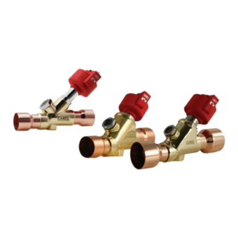
电子膨胀阀 / Electronic expansion valve / Détendeur électronique / Elektronisches Expansionsventil / Válvula de expansión electrónica
电子膨胀阀
IMPORTANT
重要提示
重要提示
仅在配合使用CAREL电子膨胀阀驱动器的情况下,CAREL将确保
Carel guarantees the correct operation of the Carel ExV, if driven by Carel drivers
电子膨胀阀的正确操作。如果未经CAREL同意,使用其他厂家的
only. The use of the Carel ExVs with other manufacturers driver, if not expressely
驱动器,电子膨胀阀的保修将自动失效。
agreed with Carel, will automatically void the warranty.
如需更多信息,请在安装产品前阅读"电子膨胀阀系统操作手
For more information, read the "EEV systems operating manual (code +030220811)
+030220811
www.carel.com的"documentation"(
册(代码
)"。该手册可从
before installing this product. The manual is available in the "documentation" downlo-
文档)下载获取。
ad area at www.carel.com.
/ Positioning
安装位置
Misura del surriscaldamento
过热度检测
Superheating detection
Superheating detection
Compressore
压缩机
Compressor
Compressor
蒸发器
Evaporatore
Condensatore
冷凝器
Evaporator
Condenser
Evaporator
Condenser
Valvola di espansione E
电子膨胀阀
X
V
EXV expansion valve
E
X
V expansion valve
焊接和操作 / Welding and handling
T. Max
650°C
30-35 Nm
1
2
注意:请用油将"O"型密封圈弄湿
Note: wet the "O" ring with oil
/ Electrical connections
电气连接
电气连接
A 款
/ TYPE A
4
Bianco/White
/White
白色
2
Giallo/Yellow
/Yellow
黄色
3
棕色/Brown
Marrone/Brown
1
绿色
/Green
Verde/Green
CAREL
E2VCAB****
0,5 Nm
90°
一般特性
一般特性
E5V , E6V , E7V是设计用于制冷系统中的制冷剂膨胀节流装置(电子膨胀阀),它通过测算过热度进行节流控制。通过安装在蒸发器
出口的压力和温度传感器,电子膨胀阀可以读取温度、压力信号,进而计算出过热度。在工作时,阀入口处的流体需要有充足的过
冷度,以防止阀内产生气态制冷剂的情况。当制冷剂充入不足或阀的下游有明显的压降时,阀的噪声可能会提高。
和CAREL的相关设备配套使用。请不要在正常运行条件之外使用E5V , E6V , E7V阀,如下所述。
安装定位
安装定位
E5V , E6V , E7V 阀是双向运行的。通常在制冷剂入口之前安装一个机械式过滤器。
除了不能上下颠倒
即电机定子朝下安装以外,阀可以朝任何方向,如图1所示。如果在膨胀阀前面使用截止阀,则必须设定好回
路,从而防止在阀附近产生流体锤。截止阀和膨胀阀绝不能同时关闭,以避免回路中压力过大而产生的风险。
建议E5V , E6V , E7V阀的安装位置同传统的机械式阀一样,即在蒸发器和任何分配器的之前。
温度和压力传感器(不和E5V , E6V , E7V阀一起提供)必须安装在紧邻蒸发器出口的位置,确保:
• 温度传感器安装时使用了导热胶,并且能充分地与外部绝热;
• 两个传感器都要安装在任何会改变压力(如阀)和/或温度(如热交换器)装置之前。
焊接和操作
焊接和操作
E5V , E6V , E7V阀必须通过将铜制接头钎焊到冷凝器出口上(IN)和蒸发器入口管上(OUT)与回路连接。如图2的说明:
1. 将阀体从包装盒内取出;
2. 在阀体上包一块湿布,焊接接头,不要使阀过热,如图2.1所示,瞄准火焰朝着接口,(为了使钎焊更好,而不影响阀体与接头之
间的焊接密封性,使用熔化温度低于650 °C的合金或使用银含量超过 25% 的合金);
3. 当阀被冷却后,使用口径为27mm的呆口扳手将视液镜紧固到阀体上有特殊螺纹的槽中,确定安装了O型密封圈(OR2081-内径为
20.35mm–厚度为1.78mm–材质为氯丁橡胶)来确保密封严密。紧固视液镜直到螺纹的末端
注意:为了确保更好的装配紧固性,请使用氯丁橡胶或 HNBR(氢化丁腈) O形圈(仅适用于 R515B 制冷剂)利用匹配的化学相容
注意:为了确保更好的装配紧固性,请使用氯丁橡胶或 HNBR(氢化丁腈) O形圈(仅适用于 R515B 制冷剂)利用匹配的化学相容
油,涂成一个薄层对其进行润滑。不同的材料可能会影响组件的正确使用。
油,涂成一个薄层对其进行润滑。不同的材料可能会影响组件的正确使用。
4. 如果尚未安装,把包装盒内的O型圈用手指套入阀头(ORM 0200-20 对应 E5V,OR3112 对应 E6V,OR3137 对应 E7V)。确保它是完整
的、干净的,安装在密封底座的恰当位置上
5. 安装O型密封圈后,使用呆口扳手(尺寸如图
Fig. 2.3)
图
注意:如果螺杆升出到管头外,请按照下列步骤操作:
• 将螺杆紧固到管头上,电机没有被插入旋转直到听到滴答一声(这表明防回转的装置回到了轴上)。
• 按照下面的指导方式(电气连接),将电机插到管头上,同时将它连接到驱动器上;
• 以手动操作方式设定驱动器,同时设定一个数字为480步(阀完全打开);开始调步数,螺杆将自定位到防回转导管内,以便
正确安装。
6. 确保红色定子已经完全被插入到管头上,用黑色的螺帽紧紧地旋到管头上,直到橡皮圈稍稍变形(紧固扭力为0.8Nm)
2.3)
Fig. 3
所示,将预接线的接头连接到步进电机的槽上,紧固螺丝,扭矩大约为0.5Nm。然后将4-pin的线连接到CAREL EVD***驱
Fig. 1
7. 如图
动器或其它被认可的CAREL控制器相对应的端口上,根据下表所列出的值设定参数。
类型
0
CAREL E
X
V
当关阀时,为了加快关闭速度,电子膨胀阀占空比可从 30% 提高到 100%,要取得更快速度,可使阀的最大励磁速度为150步/秒。
关于驱动器上的参数设置的其它信息,请参考控制器用户手册。
30-35 Nm (E
5
V-E
6
V)
不要对阀或连接管线施加扭力或变形压力。
不要对阀或连接管线施加扭力或变形压力。
35-40 Nm (E
7
V)
不要用锤子或其它物品敲击阀。
不要用锤子或其它物品敲击阀。
不要使用可能使外部结构变形或损坏内部零件的钳子或其它工具。
不要使用可能使外部结构变形或损坏内部零件的钳子或其它工具。
不要使用可调节扳手安装视液镜,以免损伤玻璃。
不要使用可调节扳手安装视液镜,以免损伤玻璃。
切勿将火焰对准阀。
切勿将火焰对准阀。
切勿将阀放在靠近磁场的地方。
切勿将阀放在靠近磁场的地方。
在下列状况下,切勿进行安装或使用阀:
在下列状况下,切勿进行安装或使用阀:
· · 外部结构变形或损坏;
外部结构变形或损坏;
3
· · 发生很严重的意外事件,例如产品摔落;
发生很严重的意外事件,例如产品摔落;
· · 电子部件被损坏(定子,接触运载装置,连接头等等)。
电子部件被损坏(定子,接触运载装置,连接头等等)。
在外部结构变形或电子部件被损坏的情况下,
在外部结构变形或电子部件被损坏的情况下,CAREL
如果有灰尘,可能会使阀出现故障。
如果有灰尘,可能会使阀出现故障。
· · 安装以后,检查密封性。
安装以后,检查密封性。
· · 在安装管头进入阀体之前,不要移动阀头,以避免装配不当。
在安装管头进入阀体之前,不要移动阀头,以避免装配不当。
· · 这个阀是个承压设备,必须安装一个独立的安全压力保护系统。
这个阀是个承压设备,必须安装一个独立的安全压力保护系统。
· · 如果超出规定的范围使用该阀,部分性能规格可能无效
如果超出规定的范围使用该阀,部分性能规格可能无效
Fig. 2
· · 在运行压力下,避免变形,撞击,火苗及液体腐浊。
在运行压力下,避免变形,撞击,火苗及液体腐浊。
· · 当阀运行中,不要拆开阀。
当阀运行中,不要拆开阀。
· · 在进行维修和拆开之前,检查并确认没有受压液体。
在进行维修和拆开之前,检查并确认没有受压液体。
电气连接
电气连接
B 款
/ TYPE B
连接一个防护等级为IP67的模压好的连接头(
1
然后连接四个电机相到驱动器,E5V, E6V , E7V上的相对应驱动器上的端口,依次类推。
Verde/Green
/Green
绿色
4
注意!相在阀定子上标示了接地标志。
Bianco/White
/White
白色
2
Giallo/Yellow
/Yellow
根据
89/336/EEC
指令和之后的修正说明,可提供一个选配的屏蔽式连接头 (E2VCABS***)。
黄色
3
棕色/Brown
Marrone/Brown
避免使用标准 DIN 43650 连接器,因为它们不能保证最佳的产品性能。
CAREL
E2VCAB****
CAREL E5V, E6V, E7V
运行规格
兼容的制冷剂:
第1组
(仅适用于
E5VxxASSx
第2组: R22, R134a, R407C, R410A, R404A, R507A, R417A, R1234ze, R448A, R449A, R450A, R513A, R407H,
R427A, R452A, R407A, R407E, R407F, (
仅适用于
最高运行压力 (PS):
对于E5V & E6V:高达45bar (653 psi) ;
对于E7V: UL认证下高达42 bar (609 psi), CE认证下高达45 bar (653 psi) ;
Tab.1
的第 1 组制冷剂
参见表
最大运行压差(MOPD):对于E6V & E7V为28 bar (406 PSI);对于E5V为35 bar (508 psi)
压力设备认证:液体I & II组,I类
UL/CSA 认证 (UL 429和CSA C22.2 no.139-2010): UL文件 n° E3045579, cURus (A1)
制冷剂温度:-40~70 °C (-40~158°F)
房间温度:-30~70 °C (-22~158°F)
关于其它运行条件或可选择的制冷剂,请联系CAREL
Fig. 3
(
Fig.2.2)
,紧固时扭矩为30-35 Nm;
如图
(
Fig. 2.2)
如图
;
Fig.
4
为30-35Nm或 E7V为35-40Nm
)拧紧阀头,确保密封严实。推荐力矩:
E5V, E6V
最小步数
最大步数
关闭步数
速度 步秒
相电流
mA
静态相电流
50
480
500
50
450
100
CAREL不能保证阀的正常运行。
不能保证阀的正常运行。
E2VCAB0***)
,1为绿色,2为黄色,3为棕色,4为白色。
CAREL E5V, E6V, E7V
定子
两极定子,低电压
)
:
R1234yf, R32, R452B,R454A, R454B, R454C, R455A
-
相电流:450 mA
控制频率:50 Hz
E5-6-7VATTxx4xx): R515B
(紧急关闭情况下,最大到150 Hz)
相电阻(25 °C):36 Ohm ± 10%
防护等级:带E2VCAB*为IP67
步距角:E
5
V & E
6
V为15°,E
7
V为7.5°
线性前进/线性步进式:0.03 mm (0.001 inch)
连接线:4芯(AWG 18/22)
完全关闭步数:500
控制步数:480
General features
The E5V, E6V, E7V electronic valve is designed for installation in refrigerant circuits as the refrigerant expansion device, using the superheat calculated by a pressure and temperature
probe located at the evaporator outlet as the control signal. The inlet fluid should be suitably subcooled to prevent the valve from operating with flash gas. Valve noise may increase
when refrigerant charge is insufficient or there is significant pressure drop downstream of the valve. Only CAREL instruments should be used for the control of the E5V, E6V, E7V. Do
E5V, E6V, E7V
not use the E5V, E6V, E7V valves outside of the normal operating conditions, shown below.
只能
Positioning
The E
5
V, E
6
V, E
7
V valve is double-acting. Always install a mechanical filter before the refrigerant inlet in order to safeguard the reliability of the valve.The valve can be oriented in
any direction with the exception that the stator must not be pointed downwards (valve upside down) as shown in Fig. 1. If using shutoff valves before the expansion valve, the
circuit must be set up so that no fluid hammer is created near the valve. The shutoff valve and expansion valve must never be closed at the same time, to avoid dangerous excess
pressure in the circuit. The recommended position for the E
5
V, E
6
V, E
The temperature and pressure sensors (not supplied with the E
5
V, E
6
• the temperature sensor is installed with conductive paste and is adequately thermally insulated from the outside;
• both the sensors are installed BEFORE any devices that vary the pressure (e.g. valves) and/or temperature (e.g. heat exchangers).
Welding and handling
The E5V, E6V, E7V valves must be joined to the circuit by braze welding the copper fittings to the condenser outlet (IN) and evaporator inlet pipes (OUT). Proceed as indicated in Fig. 2.
1. Take the body of the valve from the packaging;
2. Wrap a wet rag around the body of the valve and weld the fittings, without overheating the valve, aiming the flameat the end of the fittings as shown in Fig. 2 .1 (for better
braze welding without affecting the seal of the weld between the body and the fittings, use alloys with a melting temperature of less than 650 °C or with a silver content
higher than 25%);
3. When the valve has cooled down, tighten the flow sight glass on the valve body into the special threaded socket using a 27 mm spanner, making sure the o-ring is inserted
and intact (OR2081 –inside diameter 20.35 mm – thickness 1.78 mm) to ensure hermetic tightness. Tighten the sight glass to the end of the thread (Fig. 2.2) with 30-35 Nm torque;
Warning! To ensure better tightness of the assembly, use the Neoprene o HNBR O-ring (only with R515B refrigerant) lubricated with a thin layer of compatible
oil. Different materials can compromise the correct use of the assembly.
4. If not already assembled, insert the O-ring included in the packaging (ORM 0200-20 for E
ring, by finger. Make sure it is intact, clean, and in the correct position on the bottom of the seal seat (Fig. 2.2).
5. Tighten the steel cartridge to the special threaded socket in the valve body using fork spanner (for the size see Fig. 4), making sure the O-ring is fitted to ensure hermetic
tightness. Tighten the cartridge by pressing the ring against the valve body with a recommended torque of 30-35 Nm for E
If the threaded rod comes completely out of the cartridge, proceed as follows:
(
如
• Tighten the rod to the cartridge without the motor being inserted – turn until hearing a click (this indicates that the antirotation device is back in axis).
• Insert the motor on the cartridge (points 6-7-8) and connect it to the CAREL driver, following the instructions shown below (electrical connections).
• Set the driver in manual operation and set a number of 480 steps (complete opening); start sequence of steps, the rod will position itself inside the anti-rotation guide to
allow correct installation.
6. Make sure that the red stator is fully inserted on the cartridge with the black nut screwed on tightly until deforming the rubber ring on the stator (tightening torque 0,5 Nm).
(Fig. 2.3).
(
Fig.
如图
7. Connect the pre-wired connector to the socket on the stepper motor and tighten the screw, applying a force of around 0.5 Nm, following the instructions shown in Fig. 3. Then
connect the four-pin end of the cable to the corresponding terminals on the CAREL EVD*** driver or other approved CAREL controller, and set the parameters according to the
values shown in the table below.
no.
Model
Step min
Step max
mA
占空比
0
CAREL E
X
V
50
480
30
Carel controllers for electronic valves increase the duty cycle from 30% to 100% when closing to reduce stopping time; to further speed up this phase, the valve can be control-
led at a maximum frequency of 150 steps/sec. For further information of the parameters to be set in the driver, see the controller manual.
Do not exert torsion or deforming stress on the valve or the connection pipes.
Do not hit the valve with hammers or other objects.
Do not use pliers or other tools that may deform the external structure or damage the internal parts.
Do not use an adjustable open-end key to install the warning sight glass, to avoid damaging the sight glass.
Never aim the flame at the valve.
Never place the valve near magnetic fields.
Never install or use the valve in the event of:
• deformation or damage to the external structure;
• heavy impact, due for example to dropping;
• damage to the electrical parts (stator, contact carrier, connector,...).
CAREL does not guarantee the operation of the valve in the event of deformation of the external structure or damage to the electrical parts. IMPORTANT: the
presence of dirt particles may cause valve malfunctions.
• Following installation, check tightness at assembly pressure.
• Do not move the valve rod before having assembled the cartridge onto the body, to avoid it coming out and thus incorrect assembly on the body
• The valve is not fitted with pressure limiting devices therefore the user must install an independent excess pressure safety system.
• Use outside of the specifications may invalidate the declaration of conformity relating to the valve
• Avoid deformations, knocks, flames and corrosive liquids when operating under pressure
• Do not disassemble the valve when it is operating
• Check there is no pressurised fluid before performing maintenance or dismantling
Electrical connections
Connect an IP67 co-moulded connector only (E2VCAB0***), in which the pin mapping is 1 Green, 2 Yellow, 3 Brown, 4 White. Then connect the four motor phases to your driver
so that phase 1 of the valve corresponds to terminal 1 of the driver, and so on. (!) Important: phase no. 4 is marked on the valve stator with the earth symbol. An optional shielded
co-moulded connector is available (E2VCABS***) for applications with specifi c electromagnetic disturbance, in compliance with the standards in force, 89/336/EEC and later
amendments. Avoid using standard DIN 43650 connectors as these will not guarantee optimum product performance.
CAREL E
5
V, E
6
V, E
7
V operating specifications
Compatible with refrigerants: Group 1 (only codes E5VxxASSx): R1234yf, R32, R452B,
R454A, R454B, R454C, R455A - Group 2: R22, R134a, R407C, R410A, R404A, R507A, R417A, R1234ze, R448A,
R449A, R450A, R513A, R407H, R427A, R452A, R407A, R407E, R407F, (only codes E5-6-7VATTxx4xx): R515B
Maximum operating pressure (PS): up to 45bar (653 psi) for E5V and E6V;
for E7V, 42 bar (609 psi) with UL certification, 45 bar (653 psi) with CE;
see table 1 to Group 1 of fluids
Maximum operating ∆P (MOPD): 28 bars (406 psi) for E
6
V & E
7
V; 35 bars (508 psi) for E
P.E.D. Fluid Gr. 1 and 2, category I
UL/CSA certification (UL 429 and CSA C22.2 no.139-2010): UL file n° E3045579, cURus (A1)
Refrigerant temperature: -40T70°C (-40T158°F)
Room temperature: -30T70°C(-22T158°F)
Contact CAREL for other operating conditions or alternative refrigerants.
7
V is the same as for a traditional thermostatic valve, that is, upstream of the evaporator and any distributor.
V, E
7
V) must be positioned immediately downstream of the evaporator, making sure that:
5
V, OR3112 for E
5
V, OR3112 for E
6
V and OR3137 for E
7
V) and it seats on the cartridge
5
V and E
6
V or 35-40 for E
7
V (Fig. 2.3). Warning!
step close
Step/s speed
mA pk
mA hold
% duty
500
50
450
100
30
CAREL E
5
V, E
6
V, E
7
V stator
Bipolar stator, low voltage
Phase current: 450 mA
Control frequency: 50 Hz
(up to 150 Hz for emergency closing)
Phase resistance (25 °C): 36 Ohm ± 10%
Index of protection: IP67 with E2VCAB*
5
V
Step angle: 15° for E
5
V & E
6
V; 7,5° for E
7
V;
Linear progress/step: 0.03 mm (0,001 inches)
Connections: 4 wires (AWG 18/22)
Complete closing steps: 500
Control steps: 480
Advertisement

Related Manuals for Carel E5V


Summary of Contents for Carel E5V
- Page 1 Carel, will automatically void the warranty. • 两个传感器都要安装在任何会改变压力(如阀)和/或温度(如热交换器)装置之前。 The E5V, E6V, E7V valves must be joined to the circuit by braze welding the copper fittings to the condenser outlet (IN) and evaporator inlet pipes (OUT). Proceed as indicated in Fig. 2. 如需更多信息,请在安装产品前阅读“电子膨胀阀系统操作手...
- Page 2 O-Ring, der die hermetische Dichtigkeit garantiert, befestigt ist. Den Einsatz am Ventilkörper mit einem Drehmoment von 30-35 la abrazadera en batida en el cuerpo de la válvula con un par de apriete recomendado de 30-35 Nm para E5V y E6V ó 35-40 para E7V (Fig. 2.3).
Need help?
Do you have a question about the E5V and is the answer not in the manual?
Questions and answers