Advertisement
Available languages
Available languages
Quick Links
Scheda seriale KNX / KNX serial card
Lo standard tecnologico KNX rappresenta ormai una realtà diffusa
nel settore dell'automazione e controllo di edifici ad uso terziario
e residenziale.
The KNX technological standard is now widely used in building
automation and control for commercial and residential applications
Manuale d'uso
User manual
H i g h
E f f i c i e n c y
S o l u t i o n s
NO POWER
& SIGNAL
CABLES
TOGETHER
READ CAREFULLY IN THE TEXT!
Advertisement

Subscribe to Our Youtube Channel
Related Manuals for Carel PCOS00KXN0


Summary of Contents for Carel PCOS00KXN0
- Page 1 Scheda seriale KNX / KNX serial card Lo standard tecnologico KNX rappresenta ormai una realtà diffusa nel settore dell'automazione e controllo di edifici ad uso terziario e residenziale. The KNX technological standard is now widely used in building automation and control for commercial and residential applications Manuale d’uso User manual NO POWER...
- Page 3 Senza che ciò escluda la doverosa osservanza di ulteriori avvertenze presenti nel NO POWER manuale, si evidenza che è in ogni caso necessario, per ciascun Prodotto di CAREL: • & SIGNAL evitare che i circuiti elettronici si bagnino. La pioggia, l’umidità e tutti i tipi di...
- Page 5 .........................8 e-drofan...........................8 3. SPECIFICHE DI COMUNICAZIONE Comunicazione KNX ....................9 Comunicazione Modbus ..................9 4. USO DI ETS5 5. USO DEL DCA CAREL Menu “General Settings” ..................10 Menu “Datapoints Settings” ................11 Menu “String Tables” ....................12 Assegnazione indirizzo individuale .............13 Download configurazione ................13 6.
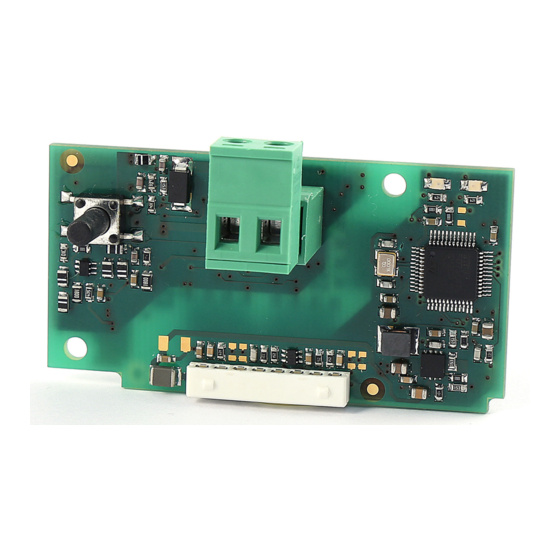
- Page 7 ETS5 professional, il Device Configuration Apps tool (DCA) (scaricabili presso l’associazione KNX) e il product database (disponibile sul sito ksa.carel.com o nel catalogo online). 1.3 Codici PCOS00KXN0 Modello per la porta pCO BMS, alloggiamento “Serial card” ed e-drofan. Green Push button Fig.
- Page 8 2. INSTALLAZIONE 2.1 pCO e c.pCO 2.2 e-drofan Con riferimento alla Fig 2.b-A/B, l’installazione nell’e-drofan si ottiene a macchina non alimentata, inserendo la scheda opzionale nel corrispondente connettore, assicurandosi che la scheda sia ben inserita. (Fig. 2.b, punti A, B). Agganciare ed avvitare il supporto plastico (da ordinare separatamente, codice PCOS00S030) come da figura 2.b, punti C e D.
- Page 9 3.1.2 Indirizzo dispositivi In una rete KNX ogni dispositivo deve avere un indirizzo univoco. La modalità supportata dalla scheda Carel verso KNX è TP1 9.6 kbits/s L’assegnazione effettiva dell’indirizzo ai dispositivi avviene, tramite System mode. connessione di rete, utilizzando il software ETS.
- Page 10 5. USO DEL DCA CAREL Il tool DCA (Device Configuration Apps) Carel è scaricabile dal sito www. Una volta che il tool DCA sia correttamente installato, è necessario knx.org. Permette di configurare il gateway Modbus-KNX in base alle utilizzare il file in formato knxprod per inserire il nuovo dispositivo nel esigenze specifiche dell’utente.
- Page 11 5.2 Menu “Datapoints Settings” Accedendo al menu “Datapoints Settings” è possibile associare i parametri Modbus disponibili nel file 2cf ai datapoint KNX richiesti. Per aggiungere un datapoint è sufficiente premere il tasto “Add” che aprirà una finestra di selezione nella quale saranno visibili tutti i parametri Modbus definiti nel file 2cf (con le relative traduzioni, se presenti, nella colonna Description).
- Page 12 5.2.1 Modbus Datapoint In tutti gli altri casi invece, i campi impostabili sono: • A, B: permettono di effettuare una trasformazione lineare sul dato. Dato Il sottomenu “Modbus Datapoint” mostra per ogni variabile aggiunta il valore X del registro Modbus, il valore trasformato è Y = A * X + B. alcuni dati che non possono essere modificati: il tipo Modbus (holding Viceversa, leggendo da KNX il valore modbus viene ottenuto secondo register, coil, input register, input), l’indirizzo di lettura e di scrittura e il...
- Page 13 5.4 Assegnazione indirizzo individuale L’assegnazione dell’indirizzo individuale della scheda KNX Carel avviene come da procedura standard. Assicurarsi che: • vi sia collegamento al BUS • il BUS sia alimentato • la scheda Carel sia collegata alla linea KNX • il controllo sia alimentato.
- Page 14 La scheda KNX Carel, come già detto, svolge la funzione di gateway Inoltre, L’indirizzo delle variabili Modbus si ottiene dall’indice degli atomi tra il bus KNX e il dispositivo Carel. Il protocollo utilizzato è Modbus supervisore inseriti nell’applicativo pCO nel seguente modo: quindi il controllo pCO/c.pCO o e-drofan devono essere configurati per...
- Page 15 7. ALLARMI E SEGNALAZIONI Significato Errore/rimedi Rosso Acceso fisso Errore assenza comunicazione modbus tra scheda KNX e pCO Configurazione: • Indirizzo pCO o e-drofan errato • Baudrate pCO non corretto • protocollo pCO o e-drofan errato Lampeggiante Errore comunicazione modbus tra scheda KNX e pCO/ e-drofan Modbus exception: •...
- Page 16 8. CARATTERISTICHE TECNICHE 8.1 Caratteristiche Tecniche Alimentazione 12 ÷ 33 V da scheda controllo Potenza assorbita: max 200 mW Alimentazione BUS 21÷32V Corrente assorbita: 5 mA TP1 9600 baud Numero massimo datapoints Morsetti a vite Sezione conduttori min. 0,2 mm max. 1,5 mm2 - 30 – 12 AWG Isolamento Bus TP Optoisolato dalla massa del controllo Grado di protezione...
- Page 17 The technical specifications shown in the manual may be changed without prior warning. The liability of CAREL in relation to its products is specified in the CAREL general contract conditions, available on the website www.CAREL.com and/or by specific agreements with customers; specifically, to the extent where allowed by applicable...
- Page 19 ......................8 e-drofan...........................8 3. COMMUNICATION SPECIFICATIONS KNX communication ....................9 Modbus communication ..................9 4. USING ETS5 5. USING THE CAREL DCA “General Settings” menu ..................10 “Datapoints Settings” menu ................11 “String Tables” menu .....................12 Assigning an individual address ..............13 Download the configuration .................13 6.
- Page 21 Device Configuration Apps tool (DCA) (downloadable from KNX) and the product database (available at ksa. carel.com or the online catalogue). 1.3 Part numbers PCOS00KXN0 model for pCO BMS port, “Serial card” socket and e-drofan. Green Push button Fig. 1.a...
- Page 22 2. INSTALLATION 2.1 pCO and c.pCO 2.2 e-drofan With reference to Fig 2.b-A/B, the optional card is installed on the e-drofan controller when powered off, inserting it correctly in the corresponding slot. (Fig. 2.b, points A, B). Fit and tighten the plastic support (to be ordered separately, P/N PCOS00S030) as shown in Figure 2.b, points C and D.
- Page 23 Device addresses In a KNX network, each device must have a unique address. The addresses The mode supported by the Carel Konnex card is TP1 9.6 kbits/s System are assigned to the devices over the network connection using the ETS mode.
- Page 24 5. USING THE CAREL DCA The Carel DCA (Device Configuration Apps) tool can be downloaded Once the DCA tool has been correctly installed, the file in knxprod format from www.knx.org. This is used to configure the Modbus-KNX gateway must be used to add the new device to the project: based on the user’s specific requirements.
- Page 25 5.2 “Datapoints Settings” menu The “Datapoints Settings” menu is used to associate the Modbus parameter in the 2cf file with the required KNX datapoints. To add a datapoint, simply click “Add”: a selection window will be displayed, containing all the Modbus parameters defined in the 2cf file (with the corresponding translations, if available, in the Description column).
- Page 26 5.2.1 Modbus Datapoint In all other cases, the following fields can be set: • A, B: allow linear conversion on the data. With the value of the Modbus For each variable that has been added, the “Modbus Datapoint” sub- register being X, the converted value Y = A * X + B. Vice-versa, if menu shows certain data that cannot be modified: Modbus type (holding reading from KNX, the Modbus value is determined using the rule X register, coil, input register, input), read/write address, and the number of...
- Page 27 5.4 Assigning an individual address The addresses of the individual Carel KNX cards are assigned using the standard procedure. Make sure that: • there is a connection to the BUS • the BUS is powered • the Carel card is connected to the KNX line •...
- Page 28 The Carel KNX card, as already described, acts as gateway between In addition, the address of the Modbus variables is obtained from the the KNX bus and the Carel device. The Modbus protocol is used, and index of the supervisor atoms entered in the pCO application, as follows: consequently the pCO/c.pCO or e-drofan controller must be configured...
- Page 29 7. ALARMS AND SIGNALS Meaning Error/solution On steady No Modbus communication between KNX card and pCO Configuration: • Incorrect pCO or e-drofan address • Incorrect pCO baud rate • Incorrect pCO or e-drofan protocol Flashing Modbus communication error between KNX card and pCO / Modbus exception: e-drofan •...
- Page 30 8. TECHNICAL SPECIFICATIONS 8.1 Technical specifications Power supply 12 - 33 V from control board Power input: max 200 mW BUS power supply 21-32V, current draw: 5 mA TP1 9600 baud Maximum number of datapoints Screw terminals Wire cross-section min. 0.2 mm max. 1.5 mm2 - 30 – 12 AWG Insulation TP bus optically isolated from the controller’s ground Ingress protection...
- Page 32 Agenzia / Agency: CAREL INDUSTRIES S.p.A. Via dell’Industria, 11 - 35020 Brugine - Padova (Italy) Tel. (+39) 049.9716611 - Fax (+39) 049.9716600 e-mail: carel@carel.com - www.carel.com...
Need help?
Do you have a question about the PCOS00KXN0 and is the answer not in the manual?
Questions and answers