Table of Contents
Advertisement
Quick Links
Advertisement
Table of Contents

Related Manuals for Kuppersbusch IKD 6700.0


Summary of Contents for Kuppersbusch IKD 6700.0
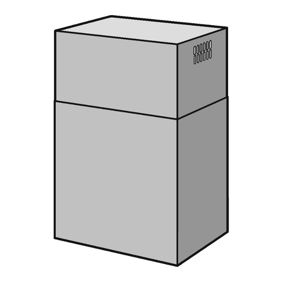
- Page 1 Cooker hood IKD 6700.0...
- Page 2 Service Manual: H5-76-02 Responsible: U. Laarmann KÜPPERSBUSCH HAUSGERÄTE AG E-mail: uwe.laarmann@kueppersbusch.de Phone: (0209) 401-732 Kundendienst Fax: (0209) 401-743 Postfach 100 132 Date: 31.08.2012 45801 Gelsenkirchen...
-
Page 3: Table Of Contents
Service Manual Contents Safety..........................4 General Information ....................... 5 Dimensions ........................6 Mounting holes ......................7 Screw specification....................7 Buttons and functions ....................9 Buttons ........................9 Functions......................10 Procedure for repairs ....................11 Changing the halogen lamp ................12 Replacing the entire lamp block ................ -
Page 4: Safety
Service Manual Safety Danger! Repairs may only be carried out by a qualified electrician! Improper repairs can be extremely dangerous for the user. It is essential that you observe the following instructions in order to prevent electric shocks: • The casing and the frame may be live in the event of faults! •... -
Page 5: General Information
Service Manual General Information A clearance of at least 30 cm must be maintained between the pan support area on the hob and the bottom of the cooker hood. If the instructions for installation of the hob specify a larger clearance, this is to be maintained. -
Page 6: Dimensions
Service Manual Dimensions For internal use only... -
Page 7: Mounting Holes
Service Manual Mounting holes Use the drilling template included in the bag of accessories to drill the holes in the ceiling. One of the axes of the drilling template must correspond to the axis of the hood control elements. Put the drilling template onto the ceiling in a vertical extension of the hob and drill the holes. Screw specification Screws for fastening onto the ceiling. - Page 8 Service Manual Screws for fastening the upper chimney, screws for fastening between upper chimney recirculation air filter (for recirculation air mode only). Dimensions: 3.9 x 9.5 mm, article no. 02000118. For internal use only...
-
Page 9: Buttons And Functions
Service Manual Buttons and functions The extractor hood is equipped with a fully automatic system for administrating all of the available functions (Advanced Sensor Control). The air in the kitchen stays pleasant and fresh without requiring any manual controls. The sensitive sensors detect any type of steam, vapours, odours and GAS and automatically adjust the hood to the required fan power. -
Page 10: Functions
Service Manual Functions Filter alarm Is shown for 30 sec. when the motor is switched off. After an operation period of 30 hours the middle segment on the display will light up to indicate that the anti-grease filter needs to be cleaned. After an operation period of 120 hours the middle segment on the display will blink to indicate that the grease filter needs to be cleaned and that the charcoal filter needs to be replaced. -
Page 11: Procedure For Repairs
Service Manual Procedure for repairs We recommend that you follow this procedure: Inspection of the product and assessment of its installation. Determine the problem and replace faulty parts if necessary. Carry out a function test to assess that the corrective action was carried out properly. First steps •... -
Page 12: Changing The Halogen Lamp
Service Manual Changing the halogen lamp If the lighting does not work the lamps will firstly need to be checked and you will need to make sure that the control switch on the control panel of the hood has not developed a fault. The hood must be disconnected from the mains power supply before it is cleaned or before any maintenance work is carried out. -
Page 13: Accessing The Control Panel
Service Manual Accessing the control panel The hood must be disconnected from the mains power supply before it is cleaned or before any maintenance work is carried out. Removing the bottom part To make it easier to access the inside of the hood, the bottom part (A) may be removed as follows: Remove all 4 marked screws (B). -
Page 14: Removing The Electrical Components
Service Manual Removing the electrical components The hood must be disconnected from the mains power supply before it is cleaned or before any maintenance work is carried out. To make it easier to access the inside of the hood, the bottom part may be removed as described in 7.1. -
Page 15: Removing The Motor Block
Service Manual Removing the motor block The hood must be disconnected from the mains power supply before it is cleaned or before any maintenance work is carried out. To make it easier to access the inside of the hood, the bottom part may be removed as described in 7.1. -
Page 16: Technical Data
Service Manual Technical data Voltage/frequency 220-240V / 50Hz Appliance dimensions (WxDxH) 600 x 430 x 880(min)/1182(max) Electrical connection 250W Halogen lighting 4 x 20W Air rate Level 1 300m³/h Level 2 475m³/h Level 3 630m³/h Level 4 740m³/h Pressure Level 1 320Pa Level 2 400Pa... -
Page 17: Faults And The Cause
Faults and the cause Attention! Repairs may only be carried out by qualified electricians or specialists! Problem Probable cause Solution The cooker hood does not work. The power cable has not been connected to a live • Check to ensure that the cable has been socket. -
Page 18: Circuit Diagram
Circuit diagram...
Need help?
Do you have a question about the IKD 6700.0 and is the answer not in the manual?
Questions and answers