
Related Manuals for SCHUNK SRU-plus-D


Summary of Contents for SCHUNK SRU-plus-D
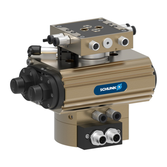
- Page 1 Original Operating Manual Assembly and Operating Manual SRU-plus-D Pneumatic swivel unit...
- Page 2 Imprint Imprint Copyright: This manual is protected by copyright. The author is SCHUNK GmbH & Co. KG. All rights reserved. Technical changes: We reserve the right to make alterations for the purpose of technical improvement. Document number: 1380765 Version: 04.00 | 11/01/2022 | en...
-
Page 3: Table Of Contents
2.13 Notes on particular risks.................. 16 Technical data...................... 18 Type key...................... 18 Basic data ...................... 19 Design and description.................... 20 Design ......................... 20 4.1.1 Variant with electrical feed-through (EDF).......... 21 Description ...................... 22 04.00 | SRU-plus-D | Assembly and Operating Manual | en | 1380765... - Page 4 Servicing shock absorber .................. 57 Replace shock absorber.................. 58 8.5.1 Replace shock absorber (base unit)............ 58 8.5.2 Replacing external shock absorber (locked center position).... 59 8.5.3 Replace internal shock absorber (locked center position) ..... 59 04.00 | SRU-plus-D | Assembly and Operating Manual | en | 1380765...
- Page 5 8.6.2 Dismantle and assemble rotary actuator (center position/locked center position).................... 62 8.6.3 Dismantling and assembling rotary actuator (fluid feed-through).. 63 Translation of original declaration of incorporation .......... 64 10 Annex to Declaration of Incorporation .............. 65 04.00 | SRU-plus-D | Assembly and Operating Manual | en | 1380765...
-
Page 6: General
Dangers for persons! Non-observance can lead to irreversible injury and even death. CAUTION Dangers for persons! Non-observance can cause minor injuries. CAUTION Material damage! Information about avoiding material damage. 04.00 | SRU-plus-D | Assembly and Operating Manual | en | 1380765... -
Page 7: Applicable Documents
• Observe the specified maintenance and lubrication intervals • Observe the ambient conditions and operating conditions Parts touching the workpiece and wear parts are not included in the warranty. 04.00 | SRU-plus-D | Assembly and Operating Manual | en | 1380765... -
Page 8: Scope Of Delivery
5518655 5514991 5514995 5514999 5515003 With fluid feed-through and center position 5516591 5518658 5516595 5516597 5516599 5516601 With fluid feed-through and locked center position 5514984 5518656 5514992 5514996 5515000 5515004 04.00 | SRU-plus-D | Assembly and Operating Manual | en | 1380765... -
Page 9: Accessories
ID no. Seal kit SRU-plus-D with EDF Basic sealing kit 5521583 5521583 5521585 5521587 5521589 5521591 5521591 Basic sealing kit + monitoring set 5521584 5521584 5521586 5521588 5521590 5521592 5521592 04.00 | SRU-plus-D | Assembly and Operating Manual | en | 1380765... -
Page 10: Basic Safety Notes
Use of unauthorized spare parts Using unauthorized spare parts can endanger personnel and damage the product or cause it to malfunction. • Use only original spare parts or spares authorized by SCHUNK. 04.00 | SRU-plus-D | Assembly and Operating Manual | en | 1380765... -
Page 11: Ambient Conditions And Operating Conditions
Due to its technical training, knowledge and experience, service the manufacturer personnel of the manufacturer is able to perform the delegated tasks and to recognize and avoid possible dangers. 04.00 | SRU-plus-D | Assembly and Operating Manual | en | 1380765... -
Page 12: Personal Protective Equipment
• Eliminate any malfunction immediately. • Observe the care and maintenance instructions. • Observe the current safety, accident prevention and environmental protection regulations regarding the product's application field. 04.00 | SRU-plus-D | Assembly and Operating Manual | en | 1380765... -
Page 13: Transport
• If the energy supply is connected, do not move any parts by hand. • Do not reach into the open mechanism or movement area of the product during operation. 04.00 | SRU-plus-D | Assembly and Operating Manual | en | 1380765... -
Page 14: Protection During Handling And Assembly
Falling and violently ejected components can cause serious injuries and even death. • Take appropriate protective measures to secure the danger zone. • Never step into the danger zone during operation. 04.00 | SRU-plus-D | Assembly and Operating Manual | en | 1380765... -
Page 15: Protection Against Dangerous Movements
• The effectiveness of the potential equalisation must be verified by executing regular safety measurements. 04.00 | SRU-plus-D | Assembly and Operating Manual | en | 1380765... -
Page 16: Notes On Particular Risks
For all work in the vicinity of hot surfaces, wear safety gloves. • Before carrying out any work, make sure that all surfaces have • cooled down to the ambient temperature. 04.00 | SRU-plus-D | Assembly and Operating Manual | en | 1380765... - Page 17 The operator must define suitable emergency stop and • restarting strategies. Emergency stop strategies: e.g. by means of controlled shut ✓ down Restarting strategies: e.g. using pressure build-up valves or ✓ suitable valve switching sequences 04.00 | SRU-plus-D | Assembly and Operating Manual | en | 1380765...
-
Page 18: Technical Data
Technical data 3 Technical data 3.1 Type key SRU-plus-D 20 - W-180 - 3 - M - 4 -M8 -AS Size 20 25 30 35 40 50 Type of damping method W = Soft Angle of rotation 90° 180° End position adjustability 3°... -
Page 19: Basic Data
The SCHUNK contact person provides support for designing further applications. More technical data is included in the catalog data sheet. Whichever is the latest version. 04.00 | SRU-plus-D | Assembly and Operating Manual | en | 1380765... -
Page 20: Design And Description
Pistons with shock absorbers Attaching center position (0°-90°-180°) Cover Back stops locked center position Cover Pistons with shock absorbers for locked center position Clamp shells Attaching locked center position (0°-90°-180°) 04.00 | SRU-plus-D | Assembly and Operating Manual | en | 1380765... -
Page 21: Variant With Electrical Feed-Through (Edf)
4.1.1 Variant with electrical feed-through (EDF) Assembly with EDF (SRU-plus-D1 50 displayed) Base unit with fluid feed-through Sensor holder with sensor Monitoring with fixed cam EDF flange Distributor plate 04.00 | SRU-plus-D | Assembly and Operating Manual | en | 1380765... -
Page 22: Description
Note: The electrical rotary feed-through (EDF) variant is only possible in combination with the fluid feed-through (MDF) variant. 04.00 | SRU-plus-D | Assembly and Operating Manual | en | 1380765... -
Page 23: Assembly
Observe the tightening torque for the mounting screws, see ✓ tightening torque table. 2. Screw attachment on the pinion with two fitting screws and } 5.2.1 two mounting screws, [/ 25]. 04.00 | SRU-plus-D | Assembly and Operating Manual | en | 1380765... - Page 24 } 5.3 [/ 33]. } 5.4.1 7. Adjust angle of rotation, [/ 35]. } 5.4.2 8. Adjust swiveling speed, [/ 38]. 9. Adjust absorber stroke, } 5.4.3 [/ 39]. } 5.5 10. Mount sensor if necessary, [/ 43]. 04.00 | SRU-plus-D | Assembly and Operating Manual | en | 1380765...
-
Page 25: Connections
Item Mounting SRU-plus-D Mounting screw M8 M8 M8 M8 M10 M12 M12 Max. depth of engagement from locating surface [mm] Centering sleeve Ø12 Ø12 Ø12 Ø12 Ø14 Ø16 Ø16 04.00 | SRU-plus-D | Assembly and Operating Manual | en | 1380765... - Page 26 Threads for M5 M6 M6 M6 M8 M10 M10 mounting screws Max. depth of engagement from locating surface [mm] Centering sleeve Ø6 Ø6 Ø6 Ø6 Ø8 Ø10 Ø10 04.00 | SRU-plus-D | Assembly and Operating Manual | en | 1380765...
- Page 27 Threads for M5 M5 M5 M5 M6 M8 M8 mounting screws Max. depth of engagement from locating surface [mm] Centering sleeve Ø8 Ø8 Ø8 Ø6 Ø8 Ø10 Ø10 04.00 | SRU-plus-D | Assembly and Operating Manual | en | 1380765...
- Page 28 If the hose-free direct connection is used, the set-screws must be removed. With the variant with electrical feed-through (EDF), assembly of the attachment with fitting screws is not possible. Attachment connection Set-screw Side air connection 04.00 | SRU-plus-D | Assembly and Operating Manual | en | 1380765...
-
Page 29: Pneumatic Connection
Extend locking position (VM) Hose connection Swiveling 0° -90° / 0° - 180° Swiveling 90° - 0° / 180° - 0° Approach center position (M) Extend locking position (VM) 04.00 | SRU-plus-D | Assembly and Operating Manual | en | 1380765... - Page 30 Variant with fluid The connections marked with numbers on the pinion and the feed-through flange are provided for feed-through of vacuum, gasses or fluids. 04.00 | SRU-plus-D | Assembly and Operating Manual | en | 1380765...
-
Page 31: Electrical Connection
Pin allocation SRU-plus-D 20-35 Pin allocation Connector A Connector B +24 VDC +24 VDC Socket 1, Pin 4 Socket 2, Pin 4 Socket 4, Pin 4 Socket 3, Pin 4 04.00 | SRU-plus-D | Assembly and Operating Manual | en | 1380765... - Page 32 Socket 5, Pin 4 Socket 3, Pin 4 Socket 7, Pin 4 Socket 4, Pin 4 Socket 8, Pin 4 not occupied not occupied not occupied not occupied 04.00 | SRU-plus-D | Assembly and Operating Manual | en | 1380765...
-
Page 33: Mounting Separating Sleeve
A and B up to the end of the threads. 4. Screw in unscrewed set-screws (4) up to the separating sleeve. 5. Mount hose connections A1, A2, B1 and B2. Position the hose connections, } 5.2.2 [/ 29]. ✓ 04.00 | SRU-plus-D | Assembly and Operating Manual | en | 1380765... -
Page 34: Settings
Optimal setting Movement End position Damping Time T Target time Swiveling speed and absorber stroke are optimal. 04.00 | SRU-plus-D | Assembly and Operating Manual | en | 1380765... -
Page 35: Adjust Swivel Angle
By incorrect setting of the swivel angle parts can come loose and the product may be damaged. Only trained stuff may set the swivel angle. • Before setting the swivel angle release pressure. • 04.00 | SRU-plus-D | Assembly and Operating Manual | en | 1380765... - Page 36 12. Tighten screw (7). Tightening torque:SRU-plus-D 20-30: 1.2 Nm/ SRU-plus-D ✓ 35-50: 2.1 Nm 13. Swivel repeatedly to test the setting, adjust if necessary. 04.00 | SRU-plus-D | Assembly and Operating Manual | en | 1380765...
- Page 37 ✓ again, if necessary adjust end position. 10. Tighten screw (6). Tightening torque:SRU-plus-D 20-40: 10 Nm/SRU-plus-D ✓ 50-60: 24 Nm 11. Swivel repeatedly to test the setting, adjust if necessary. 04.00 | SRU-plus-D | Assembly and Operating Manual | en | 1380765...
-
Page 38: Adjust Swiveling Speed
8. On the air connection B (2): Repeat the steps for the other end position. NOTE Further setting of the movement is carried out via the absorber } 5.4.3 stroke, [/ 39]. 04.00 | SRU-plus-D | Assembly and Operating Manual | en | 1380765... -
Page 39: Adjust Absorber Stroke
If the absorber stroke is too short, the assembly impacts in ✓ the end position. 2. On the first shock absorber (1): remove cover (5). 04.00 | SRU-plus-D | Assembly and Operating Manual | en | 1380765... - Page 40 9. On the second shock absorber (6) Repeat the steps for the other end position. NOTE Depending on the loading condition, the settings for the two shock absorbers may deviate widely from each other. 04.00 | SRU-plus-D | Assembly and Operating Manual | en | 1380765...
-
Page 41: Set Center Position
6. Turn stop D (6) until the pinion (7) no longer has play in the center position. 7. Tighten screw (1). Tightening torque: 20-40: 10 Nm/ 50-60: 24 Nm ✓ 8. Swivel repeatedly to test the setting, readjust if necessary. 04.00 | SRU-plus-D | Assembly and Operating Manual | en | 1380765... -
Page 42: Set Locked Center Position
10. Turn stop D (8) to the required center position. 11. Tighten screw (1). Tightening torque: 20-40: 10 Nm/ 50-60: 24 Nm ✓ 12. Swivel repeatedly to test the setting, set again if necessary, } 6.4 [/ 48]. 04.00 | SRU-plus-D | Assembly and Operating Manual | en | 1380765... -
Page 43: Mounting Inductive Proximity Switch In 80
Screw (2, 3) jams the clamping sleeve (4) and at the same ✓ time secures the bracket (9, 10, 11). 7. Tighten the screw (1), until the sensor is fixed in place. 8. Check switching positions. 04.00 | SRU-plus-D | Assembly and Operating Manual | en | 1380765... -
Page 44: Start-Up
Final angle Piston Piston Centering sleeves End position adjustability 3° Swivel range Adjustment range/ Adjustment range/ Final angle Final angle Piston Centring sleeves Piston Variant angle of rotation 90° 04.00 | SRU-plus-D | Assembly and Operating Manual | en | 1380765... -
Page 45: Base Unit
Move to basic setting 90° (center position) • Actuate air connection "C" and "D" together, pinion begins to move. Assembly swivels into center position. ✔ 04.00 | SRU-plus-D | Assembly and Operating Manual | en | 1380765... - Page 46 Start-up Electrical circuit diagram actuation with one 5/3 and one 3/2 directional control valve, example 04.00 | SRU-plus-D | Assembly and Operating Manual | en | 1380765...
-
Page 47: Locked Center Position
Before actuating "C" and "D", connections "A and "B" must be completely ventilated. Observe the waiting period here, electrical circuit diagram actuation with two 5/3 directional control valves, example [/ 48]. 04.00 | SRU-plus-D | Assembly and Operating Manual | en | 1380765... - Page 48 Start-up Electrical circuit diagram actuation with two 5/3 directional control valves, example 04.00 | SRU-plus-D | Assembly and Operating Manual | en | 1380765...
-
Page 49: Locked Center Position With Separate Piston Chambers
3. Actuate air connection "C". 4. Observe waiting period, } 6.5 [/ 50]. 5. Ventilate air connection "B1". 6. Actuate air connections "A1" and "A2". Assembly swivels until locking of C. ✔ 04.00 | SRU-plus-D | Assembly and Operating Manual | en | 1380765... - Page 50 Start-up Electrical circuit diagram holding the load at 0° 04.00 | SRU-plus-D | Assembly and Operating Manual | en | 1380765...
- Page 51 • Exhaust air throttle valves can be used for air connections "A1" and "B1" by installing separating sleeves. The air connections "A2" and "B2" then remain unthrottled. 04.00 | SRU-plus-D | Assembly and Operating Manual | en | 1380765...
-
Page 52: Troubleshooting
Too little grease in the mechanical guiding Clean and lubricate product. areas. } 8 [/ 54] Compressed air lines blocked. Check compressed air lines of damage. Swiveling speed set too fast Adjust swiveling speed } 5.4.2 [/ 38] 04.00 | SRU-plus-D | Assembly and Operating Manual | en | 1380765... -
Page 53: Product Does Not Move
} 8.6 [/ 61] Too much grease in the mechanical Clean and lubricate product. movement space. } 8 [/ 54] Pressure drops below minimum. Check air supply. } 5.2.2 [/ 29] 04.00 | SRU-plus-D | Assembly and Operating Manual | en | 1380765... -
Page 54: Maintenance
} 8.6 [/ 61]. Treat all grease areas with lubricant, } 8.2 [/ 55]. Check that the shock absorbers are working, if necessary replace shock absorber } 8.5 [/ 58] 04.00 | SRU-plus-D | Assembly and Operating Manual | en | 1380765... -
Page 55: Lubricants/Lubrication Points (Basic Lubrication)
For production reasons, shock absorbers may be of different sizes. If a shock absorber is exchanged, the new shock absorber with fitting disks must be set to the corresponding shock absorber overhang (h). 04.00 | SRU-plus-D | Assembly and Operating Manual | en | 1380765... -
Page 56: Shock Absorber Types And Overlap
0.6-466 30 W WP-M -0.1 WP-M -0.1 0.6-566 VM 0.6-466 G 35 W WP-M 19.5 -0.1 0.6-366 35 W WP-M 17.2 -0.1 WP-M -0.1 0.6-466 VM 0.6-366 G 04.00 | SRU-plus-D | Assembly and Operating Manual | en | 1380765... -
Page 57: Servicing Shock Absorber
4. Pull out the piston rod (3) and remove the compression spring (5). 5. Pull out the piston (7) with the guide sleeve (6) and dampening ring (8). 04.00 | SRU-plus-D | Assembly and Operating Manual | en | 1380765... -
Page 58: Replace Shock Absorber
[/ 55]. 9. Set safety ring (5) in the groove of the piston. 10. Turn pinion (2) to end position. Piston (3) is retracted into the housing (1). ✓ 04.00 | SRU-plus-D | Assembly and Operating Manual | en | 1380765... -
Page 59: Replacing External Shock Absorber (Locked Center Position)
Risk of injury due to spring forces! In the interior of the centering housing (locked center position variant), a pre-loaded compression spring can be found. Carefully dismantle the product. • 04.00 | SRU-plus-D | Assembly and Operating Manual | en | 1380765... - Page 60 12. Tighten screw (3) and then loosen approx. 1/4 revolution. 13. Swivel repeatedly to test the setting, if necessary readjust Electrical circuit diagram actuation with two 5/3 directional control valves (example) [/ 48]. 04.00 | SRU-plus-D | Assembly and Operating Manual | en | 1380765...
-
Page 61: Disassembly And Assembly
11. Assemble rotary actuator in the reverse order. Unless otherwise specified, secure all screws and nuts with ✓ Loctite no. 243 and tighten with the appropriate tightening torque. 04.00 | SRU-plus-D | Assembly and Operating Manual | en | 1380765... -
Page 62: Dismantle And Assemble Rotary Actuator (Center Position/Locked Center Position)
13. Assemble rotary actuator in the reverse order. Unless otherwise specified, secure all screws and nuts with ✓ Loctite no. 243 and tighten with the appropriate tightening torque. 04.00 | SRU-plus-D | Assembly and Operating Manual | en | 1380765... -
Page 63: Dismantling And Assembling Rotary Actuator (Fluid Feed-Through)
11. Assemble rotary actuator in the reverse order. Unless otherwise specified, secure all screws and nuts with ✓ Loctite no. 243 and tighten with the appropriate tightening torque. 04.00 | SRU-plus-D | Assembly and Operating Manual | en | 1380765... -
Page 64: Translation Of Original Declaration Of Incorporation
Person authorized to compile the technical documentation: Robert Leuthner, Address: see manufacturer's address Lauffen/Neckar, January 2022 p.p. Ralf Winkler; Head of Technology & Engineering, Mechanics Gripping Systems 04.00 | SRU-plus-D | Assembly and Operating Manual | en | 1380765... -
Page 65: Annex To Declaration Of Incorporation
1.2.4 Stopping 1.2.4.1 Normal stop 1.2.4.2 Operational stop 1.2.4.3 Emergency stop 1.2.4.4 Assembly of machinery 1.2.5 Selection of control or operating modes 1.2.6 Failure of the power supply 04.00 | SRU-plus-D | Assembly and Operating Manual | en | 1380765... - Page 66 External radiation 1.5.12 Laser radiation 1.5.13 Emissions of hazardous materials and substances 1.5.14 Risk of being trapped in a machine 1.5.15 Risk of slipping, tripping or falling 1.5.16 Lightning 04.00 | SRU-plus-D | Assembly and Operating Manual | en | 1380765...
- Page 67 Supplementary essential health and safety requirements for machinery intended for underground work Supplementary essential health and safety requirements for machinery presenting particular hazards due to the lifting of persons 04.00 | SRU-plus-D | Assembly and Operating Manual | en | 1380765...
- Page 68 04.00 | SRU-plus-D | Assembly and Operating Manual | en | 1380765...
- Page 72 Original Operating Manual SCHUNK GmbH & Co. KG Clamping and gripping technology Bahnhofstr. 106 - 134 D-74348 Lauffen/Neckar Tel. +49-7133-103-0 Fax +49-7133-103-2399 info@de.schunk.com schunk.com Folgen Sie uns I Follow us...
Need help?
Do you have a question about the SRU-plus-D and is the answer not in the manual?
Questions and answers