
Related Manuals for Alcatel-Lucent 9500 MPR-E


Summary of Contents for Alcatel-Lucent 9500 MPR-E
- Page 1 9500 MPR-E Microwave Packet Radio Users Manual Alcatel-Lucent Part Number 3DB18528CAAA Issue 1, March, 2008...
-
Page 3: Table Of Contents
Table of Contents General Introduction .......................1-1 Content ........................1-1 Operation General ........................2-1 Turn-On ........................2-1 Craft Terminal (CT) Provisioning Function/Operation ..........2-1 Operating Procedures ....................2-1 2.4.1 Rx Radio Protection Switching .................2-2 2.4.2 Tx Radio Protection Switching .................2-3 2.4.3 Equipment Protection Switching ................2-4 Turn-Off Procedure ....................2-5 Emergency Operation ....................2-5 Module Indicators and Connectors ................2-5 Interconnect... - Page 4 Page Startup ........................4-2 PROVISIONING Radio .................... 4-6 4.7.1 Enable Plug-In Cards ....................4-6 4.7.2 Provision Plug-In Cards ................... 4-9 4.7.3 Provision Synchronization ..................4-14 4.7.4 Provision NE Time ....................4-17 4.7.5 Crossconnect E1 Lines To Radio Module .............. 4-18 4.7.6 Provision System ....................
- Page 5 Page 6.2.2 Cross-Connecting Rules and Guidelines ..............6-4 Diagnosis Menu ...................... 6-17 6.3.1 Remote Inventory ....................6-17 6.3.2 Abnormal Conditions ....................6-18 6.3.3 Summary Block Diagram View ................6-18 Supervision Menu ....................6-19 6.4.1 Supervision Dropdown Menu ................. 6-19 6.4.2 Access State Menu ....................6-19 6.4.3 SW License ......................
- Page 6 TOC-4 This page intentionally left blank.
-
Page 7: General
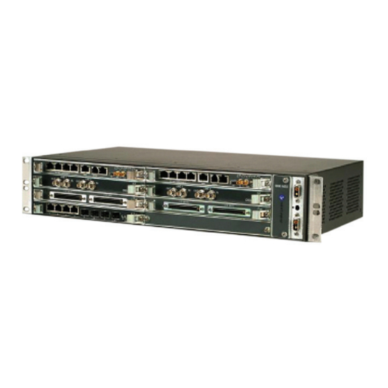
GENERAL INTRODUCTION The information in this Users Manual is a summary of the overall Operation and Mainte- nance Manual that is located on the attached CD. The summary information is provided to support initial turnup, day-to-day operation, and maintenance of the 9500 MPR equip- ment. - Page 8 9500 MPR Microwave Packet Radio ODU V2 MSS-8 Outdoor Unit Microwave Service Switch MSS-8 Slots 9500-1040P 02/20/08 Figure 1-1 9500 MPR Family...
-
Page 9: Operation
OPERATION GENERAL This section contains turn-on, normal operation, turn-off, and emergency operating proce- dures plus a description of module indicators and connectors for the 9500 MPR Series Microwave Packet Radios. Before performing any procedures, operating personnel should become familiar with the locations of power distribution units and circuit breakers. -
Page 10: Rx Radio Protection Switching
After installation and turn-on, operating procedures are limited to periodic alarm checks. Automatic and manual switching are provided for equipment protection. Manual switch- ing may be accomplished using the Craft Terminal screens on the computer. The follow- ing paragraphs provide operating procedures for manual switchover of protected radio systems. -
Page 11: Tx Radio Protection Switching
2.4.2 Tx Radio Protection Switching See Figure 2-2 and follow the steps to switch transmit traffic between the main and standby (spare) Radio Access Cards, manually, using the Craft Terminal. Switching the radio transmitter may momentarily interrupt traffic. Before switching the transmitter, obtain permission from the proper authority. JUSM_9500MP-E_1.0 - MSS12 - Administrator Help Equipment... -
Page 12: Equipment Protection Switching
2.4.3 Equipment Protection Switching Switching E1 Access Cards may momentarily interrupt traffic. Before switching E1 Access Cards, obtain permission from the proper authority. See Figure 2-3 and follow the steps to switch transmit and receive traffic (two directions with one command) between the main and standby (spare) E1 Access Cards, manually, using the Craft Terminal. -
Page 13: Turn-Off Procedure
TURN-OFF PROCEDURE The radio is designed for continuous operation. If power must be removed while perform- ing maintenance on a particular cabinet or shelf, power can be removed by turning off associated site/rack circuit breakers. Normally, the turn-off procedures are not used. System design allows maintenance of the rack without interrupting service. - Page 14 RJ 45 Connector. Side view showing the small LED lights. Link Indicator Activity Indicator On-Link Up Blinking-Tx/Rx Activity Off-Link Down Off-No Activity Alarm Status. See Core Main Module alarm status matrix. -NE MAJOR ALM (red) -NE minor ALM (red) W-NE Warning ALM (yellow) SFP Indicators...
- Page 15 Card Status LED. Indicates the status of the printed circuit board as follows: • Off – Card not equipped, not provisioned, or not powered • Green Blinking – Download, software booting, or flash card realignment in progress • Green – In service, normal operation, and properly provisioned •...
- Page 16 This page intentionally left blank.
-
Page 17: Interconnect
The information contained in this section is a summary of the infor- mation on the enclosed CD. “Refer to CD” is used throughout this sec- tion to refer the reader to the detail information on the CD. INTERCONNECT SECTION INTRODUCTION This section gives the location and describes, power connections, signal connections, and status and alarm connections for the 9500 MPR. - Page 18 Short circuiting low-voltage, low-impedance dc circuits can cause arcing that may result in burns or eye injury. Remove rings, watches, and other metal jewelry while working with primary circuits. Exercise caution to avoid shorting input power terminals. To protect maintenance personnel from antenna tower light- ning strikes, the ground system must be integrated by bond- ing frame ground and dc battery return together.
-
Page 19: E1 Connections
Do not apply battery power until it is determined that A and B battery cables with isolated returns and power cables are wired correctly. With power applied, reverse polarity on wir- ing (+batt wired to -batt pin on connector) can cause power supply fuse to blow. - Page 20 Distributor Subrack (Rear View) E1/DS1 Cable 9500-1369 11/06/07 Figure 3-4 E1 Cable Connection (Sheet 1 of 2) Distributor Subrack (Front View) 32 E1/DS1 PDH Module E1/DS1 Cable End 1 E1/DS1 Cable End 2 9500-1370 11/06/07 Figure 3-4 E1 Cable Connection (Sheet 2 of 2)
- Page 21 Table 3-1 Pin Function: Tributaries 1-16 Description Pin # Pin # Description TTIP Trib. Trib. TRING RTIP Trib. Trib. RRING TTIP Trib. Trib. TRING RTIP Trib. Trib. RRING TTIP Trib. Trib. TRING RTIP Trib. Trib. RRING TTIP Trib. Trib. TRING RTIP Trib.
- Page 22 Table 3-2 Pin Function: Tributaries 17-32 Description Pin # Pin # Description TTIP Trib. Trib. TRING RTIP Trib. Trib. RRING TTIP Trib. Trib. TRING RTIP Trib. Trib. RRING TTIP Trib. Trib. TRING RTIP Trib. Trib. RRING TTIP Trib. Trib. TRING RTIP Trib.
-
Page 23: Ethernet Cable Connections
ETHERNET CABLE CONNECTIONS Part numbers are assigned for unshielded, straight-through CAT5 UTP (PN 3AL48960AA- AL) and CAT5E UTP (PN 3AL15052AA-AL) cables. The CAT5 or CAT5E cables can be used for 10/100/1000BASE-T applications, however the CT5E cable is the recommended cable for 1000BASE-T applications. - Page 24 PAIR A PAIR B CONN 1 CONN 2 WHITE-GREEN GREEN WHITE-ORANGE ORANGE WHITE-BLUE BLUE WHITE-BROWN BROWN PAIR C LMW-9053F PAIR D 05/24/05 Figure 3-5 Straight-Through Mating Cable MDI Mode MDI-X Mode Ethernet Ethernet I/O INTFC I/O INTFC Active Active Active Active MDR-1169F 05/24/05...
- Page 25 Shelf 1 Shelf 2 Ethernet Ethernet I/O INTFC I/O INTFC TRDA+ TRDA- TRDB+ TRDB- TRDC+ TRDC- TRDD+ TRDD- MDR-1170F Cancel. Cancels XMT data in RCV output. 05/24/05 Figure 3-7 1000BASE-T Interconnect Transmit data (TRD) is both directions, simultaneously. Unwanted data is cancelled.
Need help?
Do you have a question about the 9500 MPR-E and is the answer not in the manual?
Questions and answers