Alcatel-Lucent 9500 MPR Product Information
Hide thumbs
Also See for 9500 MPR:
- User manual (200 pages) ,
- Installation practices (20 pages) ,
- Brochure (8 pages)
Table of Contents
Advertisement
Advertisement
Table of Contents

Subscribe to Our Youtube Channel
Related Manuals for Alcatel-Lucent 9500 MPR


Summary of Contents for Alcatel-Lucent 9500 MPR
- Page 1 9500 MPR Product Information PN 3EM23952AA 01 R02.00, Issue 01, September 2009...
- Page 2 NOTICE This manual applies to 9500 MPR R02.00 software. Release notes describing revisions to this software may impact operations described in this manual. This transfer of commodities, technology, or software, if from the United States, is an export in accordance with the U.S.
-
Page 3: Table Of Contents
9500 MPR UNLICENSED RADIO ........ - Page 4 3EM23952AA Issue 01, September 2009 UDS-117 GigE SFP ............3-35 Table of Contents...
- Page 5 3EM23952AA Issue 01, September 2009 9500 MPR Product Information List of Figures Figure 2-1. Frequency Plan: 5.725 to 5.850 GHz Unlicensed Band (FCC Part 15) ... . 2-13 Figure 2-2.
- Page 6 3EM23952AA Issue 01, September 2009 Figure 101-9. MSS-8 Shelf Block Diagram..........3-12 Figure 113-1.
- Page 7 9500 MPR Unit Descriptions ........
- Page 8 3EM23952AA Issue 01, September 2009 List of Tables...
-
Page 9: Fcc Part 15 Subpart B
3EM23952AA Issue 01, September 2009 FCC Part 15 Subpart B 9500 MPR UNLICENSED RADIO The JF6-9558H (unlicensed) radio provides fast deployment of service with microwave radio. No license and small antennas (no FCC requirements) allow immediate turn-up. After the license is received, the unlicensed radio can be easily converted to the lower 6 GHz licensed band. - Page 10 3EM23952AA Issue 01, September 2009 CAUTION Possibility of service interruption. Installation, Turn-Up, Maintenance, and Operation Instruction supplied with the JF6-9558H (unlicensed) radio require strict adherence for continued part 15 of the FCC Rules and IC RSS-210 compliance. FCC Part 15 Subpart B...
-
Page 11: Introduction
Signal input and output characteristics are also defined. This manual can be used by system and operations staff who plan to operate, install, commission, or maintain a 9500 MPR, and by any others who must be familiar with the equipment. -
Page 12: Documentation
• Unit Data Sheets (UDSs) in this manual • 9500 MPR Installation Practices manual (PN 3EM23953AA) • 9500 MPR Operation and Administration manual (PN 3EM23954AA) • 9500 MPR Turn-Up manual (PN 3EM23955AA) • 9500 MPR Maintenance and Trouble Clearing manual (PN 3EM23956AA) •... -
Page 13: Standards
3EM23952AA Issue 01, September 2009 Standards The following is a partial list of the standards that have influenced 1.10 certain behavioral aspects of the 9500 MPR: • 21 CFR PART 1040.10 and 1040.11 • Banned substances list • CENELEC EN 61000-3-2 •... - Page 14 • GR-1089-CORE • Human exposure • IC RSS-210 • IEC 61000-4 • ICES 003 • ICNIRP • IEC EN 60950-1 • IEC EN 50385 • IEC EN 60825-1/-2:2000 • IEC UL 60950-1 • IEC 60529 9500 MPR General System Description...
- Page 15 ITU-T G.775 • ITU-T G.823 • ITU-T G.8261 • ITU-T G.826 • ITU-T G.921 • ITU-T Recommendation K20 • ITU-T Recommendation K21 • ITU-T Recommendation K45 • ITU-T Recommendation K44 • MEF 8 • Safety (Canada) 9500 MPR General System Description...
-
Page 16: Fcc Part 15 Subpart B
Alcatel-Lucent could void the authority to operate the JF6-9558H (unlicensed) radio. CAUTION Possibility of service interruption. Installation, Turn-Up, Maintenance, and Operation Instruction supplied with the JF6-9558H (unlicensed) radio require strict adherence for continued part 15 of the FCC Rules and IC RSS-210 compliance. 9500 MPR General System Description... -
Page 17: Features
3EM23952AA Issue 01, September 2009 FEATURES This section describes 9500 MPR features of the 9500 MPR R02.00. The following paragraphs describe the features of the system for R02.00. To administer these new features by the Craft Terminal and WebEML refer to the 9500 MPR Operation and Administration manual (PN 3EM23954AA). - Page 18 Ethernet uplink with VLAN • Point-to-point VLAN • IEEE 802.1p and Diffserv QoS • Queue Management & Flow control ability • DS1/DS3 Protection • 1+1 EPS on All Cards • SW License control • SNMP v2 9500 MPR General System Description...
- Page 19 Protected 1+1 HSB, Space Diversity (SD), and Frequency Diversity (FD) Radio Nodes – 1+1 HSB, SD/FD Terminal – 1+1 HSB, SD/FD Drop and Insert Repeater – 1+1 HSB, SD/FD 4-Way Junction • 1+0 and 1+1 EPS P8ETH Ethernet Access Switch transponder module 9500 MPR General System Description...
- Page 20 The system allows up to eight radio channels per node. The radio channels can be either, all the same frequency, different frequencies, or a combination of both. LICENSED RADIO: The 6L and 6U GHz frequencies are supported in the all indoor mount arrangement. 9500 MPR General System Description 2-10...
- Page 21 Turn-Up. After the license is received, the unlicensed radio can be easily converted to the lower 6 GHz licensed band. Refer to 9500 MPR Engineering Support Documentation manual (PN 3EM23957AA) and see drawing 3EM227840000BJZZA, Equipping Options Drawing for unlicensed radio configurations and equipping options.
- Page 22 12 meters (5.8 Ghz) of the antenna. Frequency Plan: Refer to Figure for the frequency plan for the 2.13 5.725 and 5.850 GHz unlicensed band. 9500 MPR General System Description 2-12...
-
Page 23: Figure 2-1. Frequency Plan: 5.725 To 5.850 Ghz Unlicensed Band (Fcc Part 15)
65 MHz frequency separation. RF filters are centered on channels G3, B3, G3', and B3'. The flexability of the JF6-9558H allows any radio to grow to 183 Mb/s without a hardware upgrade. 950-0020-1 081809 9500 MPR General System Description 2-13... - Page 24 2.24 to 267 Mb/s full-duplex Ethernet transport capacity per radio carrier channel. MSS-8 shelf provides up to 10 Gb/s packet switching which creates 2.25 flexible aggregate capacity sharing across DS1, DS3 and Ethernet traffic. 9500 MPR General System Description 2-14...
- Page 25 2.33 Channel Spacing: 2.34 SW License control 2.35 SNMP v2 2.36 TSM8000 Support 2.37 1340 INC Support 2.38 1350 OMS Support 2.39 System Configurations Stand-Alone Microwave Service Switch (MSS-8) shelf: See Figure 2-2. 2.40 9500 MPR General System Description 2-15...
-
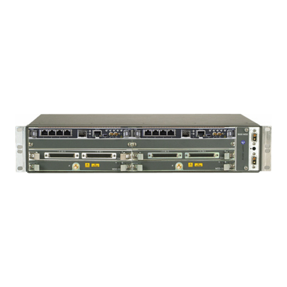
Page 26: Figure 2-2. Stand-Alone Microwave Service Switch (Mss-8) Shelf
Figure 2-2. Stand-Alone Microwave Service Switch (MSS-8) shelf All Indoor Mount - 1+0 Terminal: See Figure 2-3. 2.41 Figure 2-3. All Indoor Mount - 1+0 Terminal All Indoor Mount - 1+0 Drop and Insert Repeater: See Figure 2-4. 2.42 9500 MPR General System Description 2-16... -
Page 27: Figure 2-4. All Indoor Mount - 1+0 Drop And Insert Repeater
3EM23952AA Issue 01, September 2009 Figure 2-4. All Indoor Mount - 1+0 Drop and Insert Repeater All Indoor Mount - 1+0 4-Way Junction: See Figure 2-5. 2.43 9500 MPR General System Description 2-17... -
Page 28: Figure 2-5. All Indoor Mount - 1+0 4-Way Junction
All Indoor Mount - 1+0 8-Way Nodal Junction: See Figure 2-6. 2.44 Figure 2-6. All Indoor Mount - 1+0 8-Way Nodal Junction All Indoor Mount - 1+1 Terminal: See Figure 2-7. 2.45 Figure 2-7. All Indoor Mount - 1+0 Terminal 9500 MPR General System Description 2-18... -
Page 29: Figure 2-8. All Indoor Mount - 1+1 Hsb Drop And Insert Repeater
All Indoor Mount - 1+1 HSB Drop and Insert Repeater: See Figure 2-8. 2.46 Figure 2-8. All Indoor Mount - 1+1 HSB Drop and Insert Repeater All Indoor Mount - 1+1 HSB 4-Way Junction: See Figure 2-9. 2.47 9500 MPR General System Description 2-19... -
Page 30: Figure 2-9. All Indoor Mount - 1+1 Hsb 4-Way Junction
3EM23952AA Issue 01, September 2009 Figure 2-9. All Indoor Mount - 1+1 HSB 4-Way Junction 9500 MPR General System Description 2-20... -
Page 31: Figure 2-2. Macerate Service Switch (Mss-8)
Figure 2-2. Macerate Service switch (MSS-8) MSS-8 Configurations A MSS-8 typical configuration consists of: 2.48 • MSS-8 Typical Configuration • MSS-8 Not Protected • MSS-8 Protected Figure 2-3. MSS-8 Typical Configuration - Front View 9500 MPR General System Description 2-21... -
Page 32: Figure 2-4. Mss-8 Typical Configuration
P32E1DS1, MD300 or P2E3DS3 module can be installed in any not protected slot(s). The Main CSM (Control and Switching Module - Core) must always be in slot 1 and the Protect CSM must be in slot 2. Figure 2-5. MSS-8 Not Protected Configuration 9500 MPR General System Description 2-22... - Page 33 The Main CSM (Control and Switching Module - Core) must always be in slot 1 and the Protect CSM must be in slot 2. Refer to table for descriptions of the modular configurations the 2.49 system supports. 9500 MPR General System Description 2-23...
- Page 34 Microwave Packet Transport-Long The MPT-HL shelf supports Two MPT-HL transceiver radio Haul (MPT-HL) Shelf modules. PN: 3EM22618AA Qty: Up to 4 per 9500 MPR node Transport modules 32-port 32PDS1T1 for DS1(T1) interface Eight-port 8PETH for 10,100,1000 Ethernet Ports I/O interface types...
- Page 35 Remote Inventory (RI) provides operators with the capability to 2.53 remotely determine what equipment is installed in the system. RI data contains information programmed in the factory to indicate the configuration, capability, and compatibility of the installed circuit packs. • 9500 MPR General System Description 2-25...
- Page 36 3EM23952AA Issue 01, September 2009 9500 MPR General System Description 2-26...
-
Page 37: Unit Descriptions
3EM23952AA Issue 01, September 2009 UNIT DESCRIPTIONS Refer to table for brief descriptions of shelf assemblies, plug-in modules, and miscellaneous components used in the 9500 MPR. Table 3-A. 9500 MPR Unit Descriptions UNIT DESCRIPTION Microwave Switching Services (MSS-8) The MSS-8 houses equipment that supports 10 Gb/s... - Page 38 3EM23952AA Issue 01, September 2009 Table 3-A. 9500 MPR Unit Descriptions (cont.) UNIT DESCRIPTION DS1 D-Connector Patch Panel DS1 D-Connector Patch Panel supports up to 32 protected PN: 3DB16102AA or unprotected DS1 (Tx and Rx) interfaces. DS1 D- Qty: Up to 6per 9500 MPR node...
-
Page 39: 9500 Mpr Unit Data Sheet Cross-Reference
UDS-100 3EM23952AA Issue 01, September 2009 UDS-100 Unit Data Sheets (UDSs) 9500 MPR Unit Data Sheet Cross-Reference Unit Data Sheet Cross-Reference by UDS Number NUMBER DESCRIPTION CLEI STATUS PART NUMBER UDS-100 9500 MPR Unit Data Sheet Cross-Reference UDS-101 MSS-8 Microwave Service Switch Shelf... - Page 40 3EM20277AD GigE SFP 1000Base-ZX, 1550 nm DRR3AA6CAA Active UDS-117 3EM22617AA MPT Transceiver L6, 5725-6425 MHz Active UDS-116 3EM22617AB MPT Transceiver U6, 6425-6930 MHz Active UDS-116 3EM22618AA MPT-HL Microwave Packet transport-Long Active UDS-102 Haul Shelf 9500 MPR Unit Data Sheet Cross-Reference...
-
Page 41: Mss-8 Microwave Service Switch Shelf
UDS-101 3EM23952AA Issue 01, September 2009 UDS-101 MSS-8 Microwave Service Switch Shelf PART NUMBER/ NAME CLEI ECI/ STATUS MNEMONIC BAR CODE 3DB18001AA MSS-8 Microwave Service Active Switch Shelf FEATURES AND APPLICATION NOTES • The Microwave Service Switch (MSS-8) shelf provides cross- connection, port aggregation, switching, and equipment management. -
Page 42: Figure 101-1. Microwave Service Switch (Mss-8) Shelf
UDS-101 3EM23952AA Issue 01, September 2009 The MSS-8 shelf is 19 inches wide (17.48 inches wide without mounting flanges), 3.46 inches high (2 EIA increments), and 9.54 inches deep. Adapter plates are available to mount the MSS-8 shelf in 23 inch aluminum racks. Figure 101-1. -
Page 43: Figure 101-2. Mss-8 Shelf Slot Definitions
UDS-101 3EM23952AA Issue 01, September 2009 Figure 101-2. MSS-8 Shelf Slot Definitions (Main) (Protect) Any Transponder Any Transponder P32E1DS1 P32E1DS1 or P8ETH or P8ETH P32E1DS1 P32E1DS1 P32E1DS1 P32E1DS1 950-0004-1 072209 Table 101-A. MSS-8 Module Complement CIRCUIT PACK/ UNIT DATA SHEET PART NO. -
Page 44: Figure 101-3. Mss-8 Shelf, Unprotected Csm Configuration
UDS-101 3EM23952AA Issue 01, September 2009 MSS-8 shelf slot 1 is dedicated to the main CSM module and is required in every application. See figure 101-3 to see an example of the MSS-8 shelf configured in the unprotected CSM configuration. Slot 2 is dedicated for an optional spare CSM module for protected CSM configurations. -
Page 45: Figure 101-4. Mss-8 Shelf, Protected Csm Configuration
UDS-101 3EM23952AA Issue 01, September 2009 Figure 101-4. MSS-8 Shelf, Protected CSM Configuration (Main) (Protect) Any Transponder Any Transponder Any Transponder Any Transponder Any Transponder Any Transponder 950-0005-1 072209 MSS-8 shelves supports up to six P32E1DS1 module in unprotected DS1 aggregation configurations. -
Page 46: Figure 101-5. Mss-8 Stand-Alone Shelf, Equipped With P32E1Ds1
UDS-101 3EM23952AA Issue 01, September 2009 Figure 101-5. MSS-8 Stand-Alone Shelf, Equipped with P32E1DS1 (Main) (Protect) P32E1DS1 P32E1DS1 (Main) (Protect) P32E1DS1 P32E1DS1 (Main) (Protect) P32E1DS1 P32E1DS1 (Unprotected) (Unprotected) 950-0007-1 072209 MSS-8 shelves supports up to six P2E3DS3 modules in unprotected configurations. -
Page 47: Figure 101-6. Mss-8 Stand-Alone Shelf, Equipped With P32E1Ds1
UDS-101 3EM23952AA Issue 01, September 2009 Figure 101-6. MSS-8 Stand-Alone Shelf, Equipped with P32E1DS1 (Main) (Protect) P2E3DS3 P2E3DS3 (Main) (Protect) P2E3DS3 P2E3DS3 (Main) (Protect) P2E3DS3 P2E3DS3 (Unprotected) (Unprotected) 950-0008-1 072209 MSS-8 shelves equipped with P8ETH modules, the main P8ETH is required in slot 3 for unprotected configurations. -
Page 48: Figure 101-7. Mss-8 Shelf, All Indoor Mount, 1+0 4-Way Junction Configuration
UDS-101 3EM23952AA Issue 01, September 2009 Figure 101-7. MSS-8 Shelf, All Indoor Mount, 1+0 4-Way Junction Configuration (Main) (Protect) P8ETH Filler Panel (Main) P32E1DS1 P32E1DS1 (Main) (Protect) Filler Panel Filler Panel 950-0011-1 072209 See figure 101-8 to see an example of the MSS-8 shelf configured as an all indoor mount, 1+1 4-way junction in slots 3 and 4, with three P32E1DS1s in slot 5 through 7 in the unprotected configuration. -
Page 49: Figure 101-8. Mss-8 Shelf, All Indoor Mount, 1+1 4-Way Junction Configuration
UDS-101 3EM23952AA Issue 01, September 2009 Figure 101-8. MSS-8 Shelf, All Indoor Mount, 1+1 4-Way Junction Configuration (Main) (Protect) P8ETH P8ETH (Main) (Protect) P32E1DS1 P32E1DS1 (Unprotected) (Unprotected) P32E1DS1 Filler Panel (Unprotected) 950-0012-1 072209 MSS-8 Microwave Service Switch Shelf 3-11... -
Page 50: Figure 101-9. Mss-8 Shelf Block Diagram
UDS-101 3EM23952AA Issue 01, September 2009 FUNCTIONAL OVERVIEW MSS-8 implements functionality of grooming, routing, switching and protection, exploiting a packet oriented technology in order to meet the overall architecture. The MSS-8 CSM platform, with multiplexing and symmetrical cross-connect functions, can manage different radio directions (up to eight), with the possibility to add-drop data flows of local DS1/Ethernet traffic. - Page 51 UDS-101 3EM23952AA Issue 01, September 2009 The MSS-8 shelf houses the following modules: • CSM Control and Switching Module—houses one main and one optional protect control and switching module(s). Provides four 10/100/1000 Base-T Ethernet ports. • P32E1DS1 DS1 PDH module—houses up to six P32E1DS1 modules for DS1 TDM traffic encapsulation/extraction into standard Ethernet packets •...
- Page 52 UDS-101 3EM23952AA Issue 01, September 2009 MSS-8 Microwave Service Switch Shelf 3-14...
-
Page 53: Mpt-Hl Microwave Packet Transport-Long Haul Shelf
UDS-102 3EM23952AA Issue 01, September 2009 UDS-102 MPT-HL Microwave Packet Transport-Long Haul Shelf PART NUMBER/ NAME CLEI ECI/ STATUS MNEMONIC BAR CODE 3EM22618AA MPT-HL Microwave Packet Active transport-Long Haul Shelf FEATURES AND APPLICATION NOTES DESCRIPTION EQUIPMENT COMPLEMENT MPT-HL Microwave Packet Transport-Long Haul Shelf 3-15... - Page 54 UDS-102 3EM23952AA Issue 01, September 2009 MPT-HL Microwave Packet Transport-Long Haul Shelf 3-16...
-
Page 55: Pdu Power Distribution Unit
UDS-104 3EM23952AA Issue 01, September 2009 UDS-104 PDU Power Distribution Unit PART NUMBER/ NAME CLEI ECI/ STATUS MNEMONIC BAR CODE 3EM13317AA PDU Power Distribution Active Unit FEATURES AND APPLICATION NOTES DESCRIPTION EQUIPMENT COMPLEMENT PDU Power Distribution Unit 3-17... - Page 56 UDS-104 3EM23952AA Issue 01, September 2009 FUNCTIONAL OVERVIEW PDU Power Distribution Unit 3-18...
-
Page 57: Uds-106 Ds1 Rj-45 Patch Panel
UDS-106 3EM23952AA Issue 01, September 2009 UDS-106 DS1 RJ-45 Patch Panel PART NUMBER/ NAME CLEI ECI/ STATUS MNEMONIC BAR CODE 1AF15245AB DS1 RJ-45 Patch Panel Active FEATURES AND APPLICATION NOTES DESCRIPTION CONNECTORS FUNCTIONAL OVERVIEW DS1 RJ-45 Patch Panel 3-19... - Page 58 UDS-106 3EM23952AA Issue 01, September 2009 DS1 RJ-45 Patch Panel 3-20...
-
Page 59: Ds1 D-Connector Patch Panel
UDS-107 3EM23952AA Issue 01, September 2009 UDS-107 DS1 D-Connector Patch Panel PART NUMBER/ NAME CLEI ECI/ STATUS MNEMONIC BAR CODE 3DB16102AA DS1 D-Connector Patch Active Panel FEATURES AND APPLICATION NOTES DESCRIPTION CONNECTORS FUNCTIONAL OVERVIEW DS1 D-Connector Patch Panel 3-21... - Page 60 UDS-107 3EM23952AA Issue 01, September 2009 DS1 D-Connector Patch Panel 3-22...
-
Page 61: Csm-E Enhanced Control And Switching Module
UDS-109 3EM23952AA Issue 01, September 2009 UDS-109 CSM-E Enhanced Control and Switching Module PART NUMBER/ NAME CLEI ECI/ STATUS MNEMONIC BAR CODE 3DB18326AB CSM-E Enhanced Control Active and Switching Module FEATURES AND APPLICATION NOTES DESCRIPTION INDICATORS, CONNECTORS, AND CONTROL FUNCTIONAL OVERVIEW CSM-E Enhanced Control and Switching Module 3-23... - Page 62 UDS-109 3EM23952AA Issue 01, September 2009 CSM-E Enhanced Control and Switching Module 3-24...
-
Page 63: Uds-110 Fan Card
UDS-110 3EM23952AA Issue 01, September 2009 UDS-110 Fan Card PART NUMBER/ NAME CLEI ECI/ STATUS MNEMONIC BAR CODE 3DB18134BA Fan Card Active FEATURES AND APPLICATION NOTES DESCRIPTION CONNECTORS FUNCTIONAL OVERVIEW Fan Card 3-25... - Page 64 UDS-110 3EM23952AA Issue 01, September 2009 Fan Card 3-26...
-
Page 65: P32E1Ds1 Ds1 Pdh Module
UDS-113 3EM23952AA Issue 01, September 2009 UDS-113 P32E1DS1 DS1 PDH Module PART NUMBER/ NAME CLEI ECI/ STATUS MNEMONIC BAR CODE 3DB18126AD P32E1DS1 DS1 PDH Active Module FEATURES AND APPLICATION NOTES • Terminates up to 32 DS1 signals • Framed DS1 Bi-Directional alarm management •... -
Page 66: Figure 113-1. P32E1Ds1 Ds1 Module (Mss/Ds1) Front Panel View
UDS-113 3EM23952AA Issue 01, September 2009 ITEM FUNCTION • STATUS (S) Off - Card not equipped, not provisioned, or not powered • Green Blinking - Download, Software Booting, or Flash Module Realignment in Progress • Green - In Service, Normal Operation, and Properly Provisioned •... -
Page 67: P2E3Ds3 Ds3 Pdh Module
UDS-114 3EM23952AA Issue 01, September 2009 UDS-114 P2E3DS3 DS3 PDH Module FEATURES AND APPLICATION NOTES • Terminates up to two DS3 signals. • Framed DS3 Bi-Directional alarm management • Bi-Directional performance monitoring on framed DS3 signals • Encapsulation of DS3 data flows into standard Ethernet packets Inter Working Function (IWF) •... -
Page 68: Figure 114-1. P2E3Ds3 Ds3 Module (Mss/Ds3) Front Panel View
UDS-114 3EM23952AA Issue 01, September 2009 Figure 114-1. P2E3DS3 DS3 Module (MSS/DS3) Front Panel View FUNCTIONAL OVERVIEW In the transmit direction, the P2E3DS3 receives DS3 signals from the customer interfaces. Encapsulates the DS3 data flows into standard Ethernet packets, (IWF). The Ethernet packets are sent to the cross-connections matrix for connection to their provisioned destinations. -
Page 69: P8Eth Ethernet Access Switch Module
UDS-115 3EM23952AA Issue 01, September 2009 UDS-115 P8ETH Ethernet Access Switch Module PART NUMBER/ NAME CLEI ECI/ STATUS MNEMONIC BAR CODE 3DB18206AC P8ETH Ethernet Access Active Switch Module FEATURES AND APPLICATION NOTES • Terminates up to four GigE optical Ethernet SFP interfaces •... -
Page 70: Figure 115-1. P8Eth Module (Mss/P8Eth)
UDS-115 3EM23952AA Issue 01, September 2009 INDICATORS, CONNECTORS, AND CONTROL The P2E3DS3 DS3 PDH module has the following indicator and connectors. See figure 115-1 for P2E3DS3 DS3 PDH module front panel indicator and connectors. ITEM FUNCTION • STATUS (S) Off - Card not equipped, not provisioned, or not powered •... -
Page 71: Uds-116 Mpt Transceiver
UDS-116 3EM23952AA Issue 01, September 2009 UDS-116 MPT Transceiver PART NUMBER/ NAME CLEI ECI/ STATUS MNEMONIC BAR CODE 3EM22617AA MPT Transceiver L6, Active 5725-6425 MHz 3EM22617AB MPT Transceiver U6, Active 6425-6930 MHz FEATURES AND APPLICATION NOTES DESCRIPTION INDICATORS, CONNECTORS, AND CONTROL FUNCTIONAL OVERVIEW MPT Transceiver 3-33... - Page 72 UDS-116 3EM23952AA Issue 01, September 2009 MPT Transceiver 3-34...
-
Page 73: Uds-117 Gige Sfp
UDS-117 3EM23952AA Issue 01, September 2009 UDS-117 GigE SFP PART NUMBER/ NAME CLEI ECI/ STATUS MNEMONIC BAR CODE 3EM20277AA GigE SFP 1000Base-SX, DRR3AA3CAA 147527 Active U73234 850 nm 3EM20277AB GigE SFP 1000Base-LX, DRR3AA4CAA 147539 U73235 Active 1310 nm 3EM20277AC GigE SFP 1000Base-EX, DRR3AA5CAA 147542 U73236 Active... - Page 74 UDS-117 3EM23952AA Issue 01, September 2009 INDICATORS, CONNECTORS, AND CONTROL The SFPs have the following indicators and connector. ITEM FUNCTION LINK Off indicates GigE link is down. Green LED indicates GigE link is Up. ACTIVITY Off indicates no activity on GigE link. Blinking amber LED indicates activity on GigE link.
-
Page 75: Figure 117-1. Optical Sfp Module
UDS-117 3EM23952AA Issue 01, September 2009 Figure 117-1. Optical SFP Module Transceiver CSM SFP module Transceiver EAS SFP module Output Input Optical cables 950-0001-1 072009 On the transmitter side, the GigE SFPs has an automatic optical output power control circuit, a laser driver and a laser diode module. The transmitter is based on a non-cooled DFB laser. -
Page 76: Figure 117-2. Optical Sfp Module Block Diagram
UDS-117 3EM23952AA Issue 01, September 2009 Figure 117-2. Optical SFP Module Block Diagram SFP MODULE HOST MODULE MONITOR PIN PD LASER DRIVER VccT VccT 4.7 k TO 4.7 k 10 k TX DISABLE AUTOMATIC POWER CONTROL TX FAULT CIRCUIT (A) TRANSMITTER PIN PD PRE- POST-...
Need help?
Do you have a question about the 9500 MPR and is the answer not in the manual?
Questions and answers