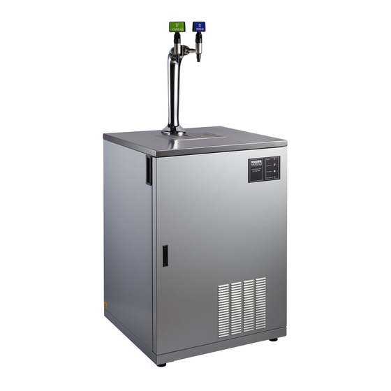
Vivreau V3-201 Service Manual
Dispensing systems
Hide thumbs
Also See for V3-201:
- Owner's manual (17 pages) ,
- Troubleshooting manual (7 pages) ,
- Commissioning instructions (4 pages)
Table of Contents
Advertisement
Quick Links
Advertisement
Table of Contents

Subscribe to Our Youtube Channel
Related Manuals for Vivreau V3-201


Summary of Contents for Vivreau V3-201
- Page 1 Service Manual V3-201 and 202 Dispensing Systems...
-
Page 2: Table Of Contents
This manual and all material provided with your system should be retained in a convenient location for future reference. Contact Vivreau if you have any questions regarding the information contained in this manual. © 2020 Vivreau Water Systems All rights reserved. -
Page 3: Safety Precautions
This manual is intended for use only by provide protection against personal injury. personnel trained in the operation of the To ensure continued protection observe Vivreau V3-201 and 202 Dispensing Systems. the following: Improper installation, adjustment, WARNING Disconnect power to the unit... -
Page 4: General Information
This manual is solely for the use of personnel Vivreau V3-201 and 202 Dispensing Systems. trained in the operation of the ViVreau V3-201 and • Information contained in this manual will help 202 Dispensing Systems only. -
Page 5: Technical Specifications
Technical Specifications GENERAL DESCRIPTION The system has been designed for operation at The Vivreau V3-201 and V3-202 Dispensing Systems ambient temperatures up to 90ºF. are designed to provide Chilled Still and Sparkling Water on demand. Dispensing Specifications Description Specification V3-201 V3-202 ΔT=18 °F @ 52.83 gal/h... - Page 6 Cooler/Carbonator Specifications Description Specification V3-201 V3-202 23.4” Width ü ü 52.9” Height ü ü Depth 23.2” ü ü 164 lbs. Weight Empty ü ü Weight Operational 201 lbs. ü ü 110/120 VAC/60 Hz Voltage ü ü Amperage ü ü...
-
Page 7: Installation
PRE-INSTALLATION Below are the services required to be in place " prior to the installation of the Vivreau V3-201 or V3- 202 Dispensing System. If you have any questions regarding these or other services, please contact Vivreau Service Toll-Free at 877-999-1044. - Page 8 Cylinder (Customer supplied) must fit within and service. Ensure all services are kept within 40” the allotted space. of the V3-201 and V3-202 Dispensing Systems. Cylinder must always remain vertical. Water Shutoff Valve to be located at low level. If connecting to a bulk or existing CO system, a Ensure there is sufficient room for a 6”...
- Page 9 A suitable location should be chosen within 40” of the electrical and water supply connections. Vivreau Model V3-201 is designed to be fitted flush on the left, right and rear. The unit incorporates a Rear Spacer. The area around the Rear Spacer must be kept clear, as warm air must vent from the top-rear of the unit.
- Page 10 If leak persists, report leak to Vivreau. Pressure: 65 PSI. Adjust Regulator as needed. WATER The Vivreau V3-201 and V3-202 Dispensing Systems provide back-flow prevention, however, it must be installed with adequate back-flow protection to Dispensing Heads comply with applicable Federal, State and Local Codes.
- Page 11 Shutoff Valve and fill the Water Tank in the chiller unit with fresh, clean water up to the overflow. Drip Tray Rear Drain (Model V3-201 shown) Fill Water Tank Ensure both Dispensers are in the closed (UP) position.
- Page 12 Secure with a Retaining Clip, and turn ON the to flush, if needed. water. Unit is ready for service. Fill out Installation Checklist and return to Vivreau. Retaining Clip Retaining Clip Location Replace Back and Service Panels, Clamp and Panel Screws.
-
Page 13: Operating Instructions
Supply Valve is open and the unit is plugged in. Bottle at a time. Place appropriate container on Drip Tray beneath Vivreau Bottles should be filled to the line in the Dispensing Head. neck just below the Cap. Chilled Still Water IMPORTANT ________________________ Pull DOWN on Blue Dispenser Handle. - Page 14 Regulator. Make sure the Sealing Washer is seated LED will illuminate and the unit will beep. Please correctly. contact Vivreau Service Toll-Free at 877-999-1044 immediately. Tighten the Nut firmly using a wrench. EMPTY DRIP TRAY: When the Drip Tray Container is FULL, a Red LED will illuminate and the unit will beep;...
-
Page 15: Maintenance
Maintenance MAINTENANCE RECOMMENDATIONS IMPORTANT ________________________ Keep the unit at peak efficiency by performing Record all yearly inspections. scheduled maintenance procedures that are recommended by the manufacturer. Proper maintenance will allow the best performance and a IMPORTANT ________________________ longer working life. Contact the factory, the factory representative or an authorized service agent to perform WARNING... - Page 16 CAUTION DAILY CLEANING files, wire brushes or scouring pads (except for stainless steel scouring pads) will mar the surface. The Vivreau V3-201 Dispensing System should be cleaned once a day. Never use steel wool, which will CAUTION Vivreau recommends using disinfectant spray or a leave behind particles that rust.
- Page 17 Carbonator Motor should never be run dry. IMPORTANT ________________________ This will cause permanent damage to the unit. Only use Vivreau recommended spare parts To reduce this risk, the Controller has a timer for cooler maintenance. Failure to do so will circuit that will automatically turn OFF the invalidate cooler approvals and warranty.
- Page 18 Remove the old Filter Cartridge by turning counter- WATER FILTRATION clockwise and pulling down. Replace the Water Filter after 25,000 gallons or every 6 months of use, whichever comes first. Follow ALL Sanitizing and Filter Change Procedures. SANITIZING AND FILTER CHANGE Make sure Do Not Use sign is WARNING displayed throughout the entire sanitation...
- Page 19 Remove the DO NOT USE Sign and carefully dispensed. inspect the water system for leaks. Plug in the Power Cord. The Vivreau Dispensing System is ready for use. Place Cleaning Switch in the ON position and allow the Carbonator to cycle completely. IMPORTANT ________________________ Place the Cleaning Switch in the OFF position.
- Page 20 Sanitizing Solution. CLEANING THE DISPENSING NOZZLES Wipe interior of Drip Tray with a clean cloth and The Vivreau V3-201 and V3-202 Dispensing sanitizing solution. Systems are equipped with removable Nozzles for ease of cleaning and sanitizing. Replace Drip Tray Lid.
- Page 21 CLEANING THE COOLING SYSTEM Rotate counter-clockwise. Remove Assembly up from Dispenser Body. CONDENSER GRILLE The Cooling System Condenser Grille is located on the front of the unit. Condenser Grille must be kept CAUTION clean to allow proper cooling of components. Unit damage will occur due to overheating! The Cooling Fins must not be blocked and must maintain a minimum distance of 4”...
- Page 22 Reassemble the Dispenser Insert spring in Dispense Handle. Press Dispenser Collar down firmly, reinsert screw Push in Plastic Insert and position with Screw. and release the spring pressure gently. Alignment of the dimple and hole illustrated by the position of the Screw. Insert Spring and Position Plastic Insert Position Dispense Handle and align holes.
-
Page 23: Parts Replacement
If worn parts need to be replaced, use OEM spare To perform this procedure, proceed as follows. parts only. Vivreau declines all responsibility for Remove two (2) Screws to remove the right side injury or damage to components due to the use lower Service Panel. - Page 24 EVAPORATOR (ICE BANK) Locate and loosen the two (2) crossbar support screws and move crossbar support off to the side. THERMOSTAT REMOVAL IMPORTANT ________________________ To access the Evaporator Thermostat, remove entire Chiller unit from cabinet. Before performing any service WARNING involving electrical connection or disconnection and/or exposure to electrical components, ALWAYS...
- Page 25 Disconnect the IEC Connector IMPORTANT ________________________ Loosen but do not remove four (4) Mounting Pay attention to Bulb’s location and ensure Screws. replacement part is installed in the same Slide Agitator to clear screw heads. location. Lift and remove Agitator from Tank. Pull Thermostat Sensing Bulb up through spacer, then down through groove in tank.
- Page 26 Remove wiring from Solenoid. CARBONATOR PUMP/MOTOR REMOVAL Remove Retaining Clips from inlet plumbing. Before performing any service WARNING involving electrical connection or disconnection and/or exposure to electrical components, ALWAYS follow Electrical LOCKOUT/ TAGOUT Procedure. Unplug or isolate unit from the main power supply. Failure to comply can cause property damage, injury or death.
- Page 27 CARBONATOR LEVEL CONTROLLER REMOVAL Before performing any service WARNING involving electrical connection or disconnection and/or exposure to electrical components, ALWAYS follow Electrical LOCKOUT/ TAGOUT Procedure. Unplug or isolate unit from the main power supply. Failure to comply can cause property damage, injury or death. Disconnect Fittings To perform this procedure, proceed as follows.
- Page 28 CARBONATOR LEVEL PROBE REMOVAL Before performing any service WARNING involving electrical connection or disconnection and/or exposure to electrical components, ALWAYS follow Electrical LOCKOUT/ TAGOUT Procedure. Unplug or isolate unit from the main power supply. Failure to comply can cause property damage, injury or death. To perform this procedure, proceed as follows.
-
Page 29: Troubleshooting
Troubleshooting The information provided in this section is intended IMPORTANT ________________________ to assist in the identification and correction of any irregularities and malfunctions which might occur Maintenance and repairs must be carried out by during operation. properly qualified and trained personnel only. Always switch OFF and unplug the equipment before performing... - Page 30 CHILLER/CARBONATOR SYSTEM (continued) Problem Possible Problem Possible Cause Action pressure too low Regulator set incorrectly Reset CO Regulator volume too Water warm Refer to ‘Water warm’ section Refer to Water warm section Air in Carbonator System not purged during Vent Carbonator for five (5) seconds connection No CO Cylinder empty...
- Page 31 Still Water is Slower Than Normal and/or Carbonator is Running Very Loud. Open Valve and Water Supply Valve Check for Proper fully Open? Operation Problem resolved Change Filter Problem resolved No Still Water If only CO dispenses, there is a water Can 3 Liters supply issue.
- Page 32 Open and Cylinder Unplug the is full. Confirm Chiller/Carbonator Confirm the leak is pressure readings and plug back in to coming from the on CO Regulator. power the system Vivreau System. OFF and back ON Repair leak. again. Problem resolved Problem resolved...
- Page 33 Service Light is ON Does Is Water Still Water On Older Model, Supply Valve to dispense from Still check Water Block. System Open and Dispenser? working? Carbonator must be reset to get the Sparkling Water to Problem resolved work again. Is Still Water Unplug the slower than...
- Page 34 Water Is Dispensing Warm Is unit plugged into a Plug in unit Problem resolved working outlet? (Blue Power Light ON.) Jump out Is Compressor Terminals on running? Thermostat Is Compressor running? Is the Confirm the Water Condenser Grille Is water Replace Replace Supply Feeding...
- Page 35 Sparkling Water is Flat Flush the Sparkling Water: 1. Switch the Cleaning Mode Switch OFF . Is CO 2. Touch and Hold the Cylinder empty? Sparkling Button until only LED Illuminated) Gas is dispensed. or below 70 PSI on 3. Release the Button and Gauge.
- Page 36 LED is ON. Drip Tray Light is ON. Is CO Empty Internal or Cylinder Valve or Check CO Pressure Is the CO Cylinder Secondary Shutoff External Drip Tray Switch and change empty? Valve closed? if needed. Container. Problem resolved Problem resolved Open CO Cylinder Replace CO...
- Page 37 Leak Is the Gasket between the Replace Gasket. Regulator and Tank in place? Connect a new CO Cylinder. Monitor level over the next 24-48 hours Did new CO Find and correct Cylinder hold leak. Water Tastes Bad pressure? Do both Problem resolved Problem resolved Does only...
-
Page 38: Illustrated Parts List
Notes are included on illustrations where needed. Ordering Parts Use this parts list to order parts for your Vivreau V3- Parts Listings 201 and V3-202 Dispensing System. Parts listings identify serviceable parts with the... - Page 39 V3-201 and V3-202 Dispensing System Exploded View 3, 4 and 5 V3-201 and V3-202 Dispensing System Parts List Item Part Number Description Top-SS-201 Stainless Still Top IMI-06-0-290-122 Agitator Compressor Capacitor Compressor 120 V Compressor Start Relay 58 1174 007 Thermostat...
- Page 40 V3-201 and V3-202 Dispensing System Exploded View (continued) V3-201 and V3-202 Dispensing System Parts List (continued) Item Part Number Description 58 0440 484 Power control board CARB-PUMP Brass Pump CARB-MOTOR Carbonator Pump Motor, 1/3 hp 120 V Carbonator Level Probe...
-
Page 42: Wiring Diagrams
Wiring Diagrams CONNECTION NOTES: 1 LIVE PRESSURE 2 NEUTRAL 3 BOOST L SWITCH PROBE 4 BOOST N 5 VALVE L 6 VALVE N GROUND 1 BLUE LEAD CATHODE ELECTRONICS EVO 50 2 CARBONATOR LED CATHODE HOUSING 3 CO2 PRESSURE LED CATHODE 4 WASTE LEVEL LED CATHODE CARBONATOR 5 COMMON LED ANODES... - Page 43 Contact Info Phone Number: +1 877 999 1044 Email: InfoUSA@vivreau.com InfoCanada@vivreau.com Or visit vivreauwater.com...
Need help?
Do you have a question about the V3-201 and is the answer not in the manual?
Questions and answers