Advertisement
Quick Links
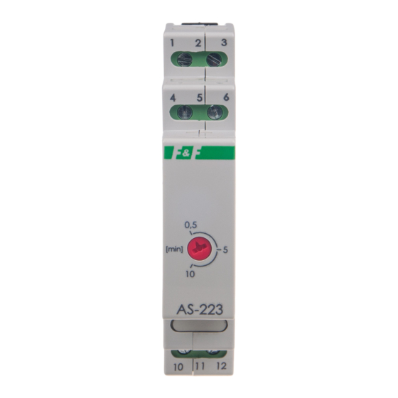
AS-223
Staircase timer
with counter-blockade
Do not dispose of this device in the trash along with other waste!
According to the Law on Waste, electro coming from households free of charge and
can give any amount to up to that end point of collec� on, as well as to store the occa-
sion of the purchase of new equipment (in accordance with the principle of old-for-
new, regardless of brand). Electro thrown in the trash or abandoned in nature, pose
a threat to the environment and human health.
Purpose
Staircase timer AS-223 serves to keep switch-ON lighting of stair-
case, corridor, or any other object for the set time and to switch-
OFF this lighting automatically, upon elapse of this set time.
Functioning
Turned ON staircase timer supports the lighting during set time
by potentiometer (from 0.5 min. to 10 min.) and upon elapse of
this set time a reduction by half of lighting brightness follows
for about 30 seconds, after that OFF follows (thus an occurrence
of a sudden darkness is avoided, enabling safe approach to the
switch). After switching OFF the lighting there is possibility to
switch it ON again. Function of counter blockade does not allow
to keep the light-ON in case of staircase switch blocking (after
blocking the pushbutton, for example by match, the timer will
count the set time and switch OFF the lighting). Next switching
ON can be after removing the blockade.
F&F Filipowski sp. j.
Konstantynowska 79/81, 95-200 Pabianice, POLAND
phone/fax (+48 42) 215 23 83 / (+48 42) 227 09 71
www.fif.com.pl; e-mail: biuro@fif.com.pl
- 1 -
Advertisement

Related Manuals for F&F AS-223


Summary of Contents for F&F AS-223
- Page 1 Purpose Staircase timer AS-223 serves to keep switch-ON lighting of stair- case, corridor, or any other object for the set time and to switch- OFF this lighting automatically, upon elapse of this set time.
-
Page 2: Wiring Diagram
Mounting 1. Take OFF the power. 2. Put on the relay on the rail in switchgear box. 3. Connect the power cable to terminals 1-3 in accordance with choosen options control the relay (control impulse L or N). 4. Timer switches which were connect with parallel, connect to terminal 6 and to cable which is connecting to terminal 3 5. - Page 3 AS-223 can work with backlit buttons. power supply relay’s power supply 165÷265 V AC control inputs control input contact output – break contact (passive) input – COM power supply contact output – closing contact (active) - 3 -...
- Page 4 Technical data power supply 165÷265 V AC contact separowany 1×NO/NC maximum load current (AC-1) 16 A control pulse 165÷265 V AC <20 mA total backlight current control buttons 5 mA activation delay 0.1÷0.2 s deactivation delay (adjustable) 0.5÷10 min. power consumption standby 0.15 W 0.7 W...
-
Page 5: Power Table
Power table tungsten halogen fluorescent energy-saving 2000 W 1250 W 1000 W 500 W 250 W The above data are indicative and will heavily depend on the design of a specific receiver (that is especially important for LED bulbs, energy-saving lamps, electronic transformers and pulse power supply units), switching frequency and operating conditions.