Table of Contents
Advertisement
Quick Links
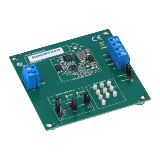
bq24650EVM Synchronous, Switch-Mode, Battery Charge
This user's guide describes the features and operation of the bq24650EVM Evaluation Module (EVM). The
EVM assists users in evaluating the bq24650 synchronous battery charger. The EVM is also called the
HPA639 A. The manual includes the bq24650EVM bill of materials, board layout, and schematic.
..................................................................................................................
1
1.1
1.2
1.3
1.4
1.5
2
2.1
2.2
2.3
2.4
2.5
2.6
2.7
3
4
4.1
4.2
4.3
1
...................................................................................................................
2
3
.................................................................................................................
4
5
6
7
8
1
2
Control and Key Parameters Settings
3
Recommended Operating Conditions
4
Bill of Materials
SLUU444A - August 2010 - Revised October 2010
Submit Documentation Feedback
.............................................................................................................
................................................................................................
......................................................................................................
...............................................................................................................
...........................................................................................................
................................................................................................................
...............................................................................................................
..............................................................................................................
...........................................................................................................
...................................................................................................
...........................................................................................................
......................................................................................................
....................................................................................................
......................................................................................................
.........................................................................................................
..............................................................................................................
...............................................................................................................
..............................................................................................................
..........................................................................................................
.................................................................................................
...............................................................................................................
....................................................................................
....................................................................................
.............................................................................................................
bq24650EVM Synchronous, Switch-Mode, Battery Charge Controller for Solar
Copyright © 2010, Texas Instruments Incorporated
SLUU444A - August 2010 - Revised October 2010
Controller for Solar Power
Contents
...........................................................................
...........................................................................
.......................................................................
List of Figures
..................................................................
List of Tables
User's Guide
2
2
2
2
3
3
5
5
5
5
5
5
6
7
9
10
10
11
17
6
11
12
13
14
15
16
17
2
3
3
10
1
Power
Advertisement
Table of Contents

Related Manuals for Texas Instruments bq24650EVM


Summary of Contents for Texas Instruments bq24650EVM
-
Page 1: Table Of Contents
Synchronous, Switch-Mode, Battery Charge Controller for Solar Power This user's guide describes the features and operation of the bq24650EVM Evaluation Module (EVM). The EVM assists users in evaluating the bq24650 synchronous battery charger. The EVM is also called the HPA639 A. -
Page 2: Introduction
Connected to system J2–VOUT Connected to charger output J2–PGND Ground J2–TS Temperature qualification voltage Input bq24650EVM Synchronous, Switch-Mode, Battery Charge Controller for Solar SLUU444A – August 2010 – Revised October 2010 Power Submit Documentation Feedback Copyright © 2010, Texas Instruments Incorporated... -
Page 3: Control And Key Parameters Settings
Operating junction temperature range, T °C The bq24650EVM board requires a regulated supply approximately 1 V minimum above the regulated voltage of the battery pack to a maximum input voltage of 28 Vdc. The charge voltage is programmed via a resistor divider from the battery to ground, with the midpoint tied to the VFB pin. - Page 4 SRP and SRN is fixed at 40 mV. 40 mV CHARGE It is set at 2 Adc from the factory. bq24650EVM Synchronous, Switch-Mode, Battery Charge Controller for Solar SLUU444A – August 2010 – Revised October 2010 Power Submit Documentation Feedback...
-
Page 5: Test Summary
4. Precautions must be observed to avoid touching areas of the assembly that may get hot or present a shock hazard during testing. Quality 1. Test data can be made available on request from Texas Instruments. Apparel 1. Electrostatic smock 2. -
Page 6: Equipment Setup
LEDPWR TEST POINTS SETTINGS Figure 1. Original Test Setup for HPA639 A Evaluation Board bq24650EVM Synchronous, Switch-Mode, Battery Charge Controller for Solar SLUU444A – August 2010 – Revised October 2010 Power Submit Documentation Feedback Copyright © 2010, Texas Instruments Incorporated... -
Page 7: Procedure
J2 (SYS, PGND). Resume other status as in Section 2.7.3. (Short JP1, JP4, set LOAD#2 to 10.5 V.) SLUU444A – August 2010 – Revised October 2010 bq24650EVM Synchronous, Switch-Mode, Battery Charge Controller for Solar Power Submit Documentation Feedback Copyright © 2010, Texas Instruments Incorporated... - Page 8 Ensure that I(J2(VOUT))= 0 A ±100 mA and → (J2(VSYS)) = 2.4 A ±200 mA. 2.7.7 Test Complete Turn off the power supply, and remove all connections from the unit under test. bq24650EVM Synchronous, Switch-Mode, Battery Charge Controller for Solar SLUU444A – August 2010 – Revised October 2010 Power Submit Documentation Feedback...
-
Page 9: Pcb Layout Guideline
6. Decoupling capacitor(s) for the charger input must be placed close to the Q1A drain and Q1B source. 7. Take the EVM layout for design reference. SLUU444A – August 2010 – Revised October 2010 bq24650EVM Synchronous, Switch-Mode, Battery Charge Controller for Solar Power Submit Documentation Feedback... -
Page 10: Bill Of Materials, Board Layout, And Schematic
Bumper foot (install after final wash) 0.440 x 0.2 SJ-5303 Shunt, 100-mil, Black 0.100 929950-00 bq24650EVM Synchronous, Switch-Mode, Battery Charge Controller for Solar SLUU444A – August 2010 – Revised October 2010 Power Submit Documentation Feedback Copyright © 2010, Texas Instruments Incorporated... -
Page 11: Board Layout
Bill of Materials, Board Layout, and Schematic www.ti.com Board Layout Figure 2. Top Layer SLUU444A – August 2010 – Revised October 2010 bq24650EVM Synchronous, Switch-Mode, Battery Charge Controller for Solar Power Submit Documentation Feedback Copyright © 2010, Texas Instruments Incorporated... -
Page 12: Second Layer
Bill of Materials, Board Layout, and Schematic www.ti.com Figure 3. Second Layer bq24650EVM Synchronous, Switch-Mode, Battery Charge Controller for Solar SLUU444A – August 2010 – Revised October 2010 Power Submit Documentation Feedback Copyright © 2010, Texas Instruments Incorporated... -
Page 13: Third Layer
Bill of Materials, Board Layout, and Schematic www.ti.com Figure 4. Third Layer SLUU444A – August 2010 – Revised October 2010 bq24650EVM Synchronous, Switch-Mode, Battery Charge Controller for Solar Power Submit Documentation Feedback Copyright © 2010, Texas Instruments Incorporated... -
Page 14: Bottom Layer
Bill of Materials, Board Layout, and Schematic www.ti.com Figure 5. Bottom Layer bq24650EVM Synchronous, Switch-Mode, Battery Charge Controller for Solar SLUU444A – August 2010 – Revised October 2010 Power Submit Documentation Feedback Copyright © 2010, Texas Instruments Incorporated... -
Page 15: Top Assembly
Bill of Materials, Board Layout, and Schematic www.ti.com Figure 6. Top Assembly SLUU444A – August 2010 – Revised October 2010 bq24650EVM Synchronous, Switch-Mode, Battery Charge Controller for Solar Power Submit Documentation Feedback Copyright © 2010, Texas Instruments Incorporated... -
Page 16: Bottom Assembly
Bill of Materials, Board Layout, and Schematic www.ti.com Figure 7. Bottom Assembly bq24650EVM Synchronous, Switch-Mode, Battery Charge Controller for Solar SLUU444A – August 2010 – Revised October 2010 Power Submit Documentation Feedback Copyright © 2010, Texas Instruments Incorporated... -
Page 17: Schematic
Bill of Materials, Board Layout, and Schematic www.ti.com Schematic Figure 8. bq24650EVM Schematic SLUU444A – August 2010 – Revised October 2010 bq24650EVM Synchronous, Switch-Mode, Battery Charge Controller for Solar Power Submit Documentation Feedback Copyright © 2010, Texas Instruments Incorporated... - Page 18 Evaluation Board/Kit Important Notice Texas Instruments (TI) provides the enclosed product(s) under the following conditions: This evaluation board/kit is intended for use for ENGINEERING DEVELOPMENT, DEMONSTRATION, OR EVALUATION PURPOSES ONLY and is not considered by TI to be a finished end-product fit for general consumer use. Persons handling the product(s) must have electronics training and observe good engineering practice standards.
- Page 19 TI products. TI’s provision of these resources does not expand or otherwise alter TI’s applicable warranties or warranty disclaimers for TI products. TI objects to and rejects any additional or different terms you may have proposed. IMPORTANT NOTICE Mailing Address: Texas Instruments, Post Office Box 655303, Dallas, Texas 75265 Copyright © 2021, Texas Instruments Incorporated...
Need help?
Do you have a question about the bq24650EVM and is the answer not in the manual?
Questions and answers