
Related Manuals for Texas Instruments bqSWITCHER bq241 Series


Summary of Contents for Texas Instruments bqSWITCHER bq241 Series
- Page 1 Using the bq241xx (bqSWITCHER™) User's Guide Literature Number: SLUU200A July 2004 – Revised December 2007...
- Page 2 SLUU200A – July 2004 – Revised December 2007 Submit Documentation Feedback...
-
Page 3: Table Of Contents
Contents ........................ Introduction ....................... Background ................Performance Specification Summary ......................Test Summary ......................Equipment ....................... Setup ....................Test Procedure ........................Schematic ....................... Physical Layouts ....................Board Layout ......................List of Materials ....................... References ....................... Important Notices SLUU200A – July 2004 – Revised December 2007 Table of Contents Submit Documentation Feedback... - Page 4 List of Figures ....................bq241xxEVM Schematic ....................bq241xxEVM Top Assembly .................... bq241xxEVM Top Silk Screen ....................bq241xxEVM Top Layer ....................bq241xxEVM Bottom Layer List of Tables ..................Performance Specification Summary ........I/O and Jumper Connections (Factory Jumper Selections shown in Bold Text) ..................
-
Page 5: Introduction
1) and data sheet (SLUS606) for information on how to change R10 and R11 values to use with an external thermistor bqSWITCHER is a trademark of Texas Instruments. SLUU200A – July 2004 – Revised December 2007 Using the bq241xx (bqSWITCHER™) -
Page 6: Test Summary
www.ti.com Test Summary Table 1. Performance Specification Summary SPECIFICATION TEST CONDITIONS UNIT Input DC voltage, V +0.6 I(DC) Battery charge current, I 1.33 O(CHG) 5 V ≤ V ≤ 16 V, V Power dissipation bq24100 = 4.2 V, I = 1.33 A (BAT) (1 cell) 5 V ≤... -
Page 7: Test Procedure
www.ti.com Test Summary Table 2. I/O and Jumper Connections (Factory Jumper Selections shown in Bold Text) ASSEMBLY –001 –002 –003 –004 –005 -006 Device bq24100 bq24105 bq24113 bq24115 bq24103 bq24103A DC+/DC-:Input 5 to 16 +0.8 to 16 5 to 16 +0.8 to 16 5 to 16 5 to 16... - Page 8 www.ti.com Test Summary 6. When the current reaches the taper termination threshold, set by the R resistor, the charge is SET2 terminated. The PG LED should be still lit and the STAT1 LED should turn off and STAT2 LED lights. 7.
-
Page 9: Schematic
www.ti.com Schematic Schematic Figure 1 shows the schematic diagram for the EVM. Figure 1. bq241xxEVM Schematic SLUU200A – July 2004 – Revised December 2007 Using the bq241xx (bqSWITCHER™) Submit Documentation Feedback... -
Page 10: Physical Layouts
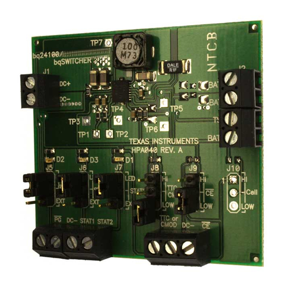
www.ti.com Physical Layouts Physical Layouts This chapter contains the board layout and assembly drawings for the EVM. Board Layout Figure 2 shows the top assembly of the EVM. Figure 3 shows the top silk screen. Figure 4 shows the top layer. -
Page 11: Bq241Xxevm Top Silk Screen
www.ti.com Physical Layouts Figure 3. bq241xxEVM Top Silk Screen Figure 4. bq241xxEVM Top Layer SLUU200A – July 2004 – Revised December 2007 Using the bq241xx (bqSWITCHER™) Submit Documentation Feedback... -
Page 12: Bq241Xxevm Bottom Layer
www.ti.com Physical Layouts Figure 5. bq241xxEVM Bottom Layer Using the bq241xx (bqSWITCHER™) SLUU200A – July 2004 – Revised December 2007 Submit Documentation Feedback... -
Page 13: List Of Materials
www.ti.com List of Materials List of Materials Table 3 through Table 7 list the components used in this design. With minor component adjustments this design could be modified to meet a wide range of applications. (1) (2) (3) (4) (5) Table 3. -
Page 14: Bq24105Evm-002 List Of Materials
www.ti.com List of Materials (1) (2) (3) (4) (5) Table 4. bq24105EVM-002 List of Materials REFERENCE DESCRIPTION SIZE PART NUMBER DESIGNATOR Capacitor, ceramic, 10 µF, 25 V, X5R, 20% C1, C2, C4 1206 Panasonic ECJ-3YB1E106M Capacitor, ceramic, 10 µF, 25 V, X5R, 20% 1206 Panasonic ECJ-3YB1E106M... -
Page 15: Bq24113Evm-003 List Of Materials
www.ti.com List of Materials (1) (2) (3) (4) (5) Table 5. bq24113EVM-003 List of Materials REFERENCE DESCRIPTION SIZE PART NUMBER DESIGNATOR Capacitor, ceramic, 10 µF, 25 V, X5R, 20% C1, C2, C4 1206 Panasonic ECJ-3YB1E106M Capacitor, ceramic, 10 µF, 25 V, X5R, 20% 1206 Panasonic ECJ-3YB1E106M... -
Page 16: Bq24115Evm-004 List Of Materials
www.ti.com List of Materials (1) (2) (3) (4) (5) Table 6. bq24115EVM-004 List of Materials REFERENCE DESCRIPTION SIZE PART NUMBER DESIGNATOR Capacitor, ceramic, 10 µF, 25 V, X5R, 20% C1, C2, C4 1206 Panasonic ECJ-3YB1E106M Capacitor, ceramic, 10 µF, 25 V, X5R, 20% 1206 Panasonic ECJ-3YB1E106M... -
Page 17: Bq24103Evm-005 List Of Materials
www.ti.com List of Materials (1) (2) (3) (4) (5) Table 7. bq24103EVM-005 List of Materials REFERENCE DESCRIPTION SIZE PART NUMBER DESIGNATOR Capacitor, ceramic, 10 µF, 25 V, X5R, 20% C1, C2, C4 1206 Panasonic ECJ-3YB1E106M Capacitor, ceramic, 10 µF, 25 V, X5R, 20% 1206 Panasonic ECJ-3YB1E106M... -
Page 18: References
www.ti.com References (1) (2) (3) (4) (5) Table 8. bq24103AEVM-006 List of Materials REFERENCE DESCRIPTION SIZE PART NUMBER DESIGNATOR Capacitor, ceramic, 10 µF, 25 V, X5R, 20% C1, C2, C4 1206 Panasonic ECJ-3YB1E106M Capacitor, ceramic, 10 µF, 25 V, X5R, 20% 1206 Panasonic ECJ-3YB1E106M... -
Page 19: Important Notices
EVALUATION BOARD/KIT IMPORTANT NOTICE Texas Instruments (TI) provides the enclosed product(s) under the following conditions: This evaluation board/kit is intended for use for ENGINEERING DEVELOPMENT, DEMONSTRATION, OR EVALUATION PURPOSES ONLY and is not considered by TI to be a finished end-product fit for general consumer use. Persons handling the product(s) must have electronics training and observe good engineering practice standards. - Page 20 Mailing Address: Texas Instruments, Post Office Box 655303, Dallas, Texas 75265 Copyright © 2007, Texas Instruments Incorporated EVM WARNINGS AND RESTRICTIONS It is important to operate this EVM within the input voltage range of 0.6 V to 16 V and the output voltage range of 0.6 V to 16 V.
- Page 21 TI as compliant with ISO/TS 16949 requirements. Buyers acknowledge and agree that, if they use any non-designated products in automotive applications, TI will not be responsible for any failure to meet such requirements. Following are URLs where you can obtain information on other Texas Instruments products and application solutions: Products...
- Page 22 Mouser Electronics Authorized Distributor Click to View Pricing, Inventory, Delivery & Lifecycle Information: Texas Instruments BQ24103AEVM BQ24115EVM BQ24105EVM BQ24103EVM BQ24113EVM BQ24100EVM...
Need help?
Do you have a question about the bqSWITCHER bq241 Series and is the answer not in the manual?
Questions and answers