Table of Contents
Advertisement
Quick Links
Advertisement
Table of Contents

Related Manuals for Honda EZ3000CX


Summary of Contents for Honda EZ3000CX
-
Page 2: A Few Words About Safety
Honda must determine the risks to their personal safety and the operation of this product. If you need to replace a part, use Honda Genuine parts with the correct part number or an equivalent part. We strongly recommend that you do not use replacement parts of inferior quality. - Page 3 Important Safety precautions Make sure you have a clear understanding of all basic shop safety practices and are wearing appropriate clothing and using safety equipment. When performing any service task, be especially careful of the following: Read all of the instructions before you begin, and make sure you have the tools, the ...
-
Page 4: Introduction
This includes text, figures, and tables. As you read this manual, you will find information that is preceded by a symbol. The purpose of this message is to help prevent damage to this Honda product, other property, or the environment. SAFETY MESSAGES Your safety and the safety of others are very important. -
Page 5: Service Rules
SERVICE RULES Use Honda Genuine or Honda-recommended parts and lubricants or their equivalents. Parts that do not meet Honda’s design specifications may damage the unit. Use the special tools designed for the product. Install new gaskets, O-rings, etc. when reassembling. -
Page 6: Table Of Contents
Table of Contents A Few Words About Safety ......................2 INTRODUCTION ........................4 SERVICE RULES ........................5 SYMBOLS ..........................5 1. SPECIFICATIONS ........................8 1-1. SPECIFICATIONS ......................8 1-2. PERFORMANCE CURVE ....................9 1-3. GENERAL DESCRIPTION .................... 12 1-4. SERIAL NUMBER ......................13 2. - Page 7 4. TROUBLE SHOOTING ......................39 ENGINE DOESN’T START. 4-1..................... 40 4-2.NO ELECTRICITY AT THE A.C. RECEPTACLE............. 41 4-3. ALTERNATING CURRENT VOLTAGE IS 0V..............42 4-4. ALTERNATING CURRENT VOLTAGE IS LOW (50~80V)..........43 4-5. CHECKING STATOR ....................44 4-6.
-
Page 8: Specifications
1-1. SPECIFICATIONS MODEL EZ3000CX ★ENGINE Model Honda GP200 Displacement ℓ Oil Capacity Regarding detailed specification, please refer and confirm HONDA ENGINE shop manual. ★GENERATOR Type Self-exciting, 2pole, field rotating type Voltage regulation system Phase Single Rated power factor R, REH,... -
Page 9: Performance Curve
1-2. PERFORMANCE CURVES -The curve shows performance of the generator under the average conditions. -Performance may vary to some degree depending on ambient temperature and humidity. -The output voltage will be higher the usual when the generator is still cold, immediately the engine starts. - Page 10 L, LB Type AC EXTERNAL CHARACTERISTIC CURVES S, SB Type AC EXTERNAL CHARACTERISTIC CURVES...
- Page 11 LS Type AC EXTERNAL CHARACTERISTIC CURVES...
-
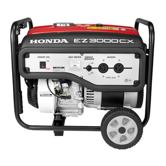
Page 12: General Description
1-3. GENERAL DESCRIPTION A IR C L E A N E R M A IN T E N A N C E C L E AN E L E ME N T E VE RY 5 0 H OU RS ( E VE RY 1 0 H OU RS U N D E R D U S T Y C ON D IT ION S ) . -
Page 13: Serial Number
1-4. SERIAL NUMBER Serial number is stamped on the label stuck on the fuel tank. Always specify serial number when inquiring about the generator or ordering spare parts in order to get correct parts and accurate service. ENGINE SERIAL NUMBER GENERATOR SERIAL NUMBER... -
Page 14: Maintenance
100Hrs. page 20Hrs. 50Hrs. 300Hrs. ITEM Engine oil Check level Change Air cleaner Check Refer Clean O (1) HONDA ENGINE Spark plug Check-Clean shop manual. Replace Valve Check-Adjust O (2) clearance Combustion Clean After every 500 Hrs.(2) Chamber... -
Page 15: Fuel Tank And Filter Cleaning
2-2. FUEL TANK AND FILTER CLEANING WARNING Gasoline is highly flammable explosive.You can be burned or seriously injured when handing fuel. Keep heat, sparks, and flame away. OFF Position Handle fuel only outdoors. Wipe up spills immediately. 1) Drain the fuel into a suitable container. 2) Turn the fuel valve to the “OFF”... -
Page 16: Fuel Tube Check
6) Clean the sediment cup, O-ring, and filter in nonflammable or high flash point solvent. Filter 7) Reinstall the filter, O-ring, and sediment cup. O-ring can not be reused. Replace with new. O-ring Tightening torque: 4.5 N•m Sediment cup 8) Install a new O-ring to the fuel valve and install them to the fuel tank. 9) Tighten the fuel valve to the special torque. -
Page 17: Removal And Installation
Muffler bracket mount bolt brush holder mount bolt AVR unit mount bolt STANDARD TORQUE VALUES Torque Values Thread Dia. Item Remark (N・m) (mm) Screw Bolt and nut 15.0 Regarding Engine torque values, please refer and confirm HONDA ENGINE shop manual. - Page 18 HOW TO CONNECTION A WIRING...
-
Page 19: Removal
3-2. REMOVAL 3.2.1 CONTROL PANEL AND CONTROL BOX 1) Remove the end cover. Bolt (M5-12L) (2) Bolt End cover Green/Yellow wire 2) Remove the wiring from the control White wire panel to the alternator. 3) Remove the Black wire and White wire Bolt from terminal block. - Page 20 Type: R, S CIRCUIT BREAKER SWITC VOLT METER Screw (M4-16) (2) AC OUTPUT GROUND TERMINAL Black wire White wire Green wire Black wire Black wire Green/Yellow wire To Alternator wiring Green/Yellow wire Connect for the bracket To Engine wiring Black wire White wire To Alternator wiring Connect for the block terminal...
- Page 21 Type: RK, MK, LS CIRCUIT BREAKER VOLT METER SWITCH Screw (M4-16) (2) AC OUTPUT GROUND TERMINAL White wire Black wire Black wire Green wire Black wire Green/Yellow wire Black wire White wire To Alternator wiring Connect for the block terminal Green/Yellow wire To Engine wiring To Alternator wiring...
- Page 22 Type: REH CIRCUIT BREAKER VOLT METER SWITCH Screw (M4-16) (2) AC OUTPUT GROUND TERMINAL Black wire Black wire White wire Green wire Black wire Green/Yellow wire Black wire White wire To Alternator wiring Connect for the block terminal To Engine wiring Green/Yellow wire To Alternator wiring Connect for the bracket...
- Page 23 Type: M CIRCUIT BREAKER SWITC VOLT METER Screw (M4-16) (2) AC OUTPUT GROUND TERMINAL White wire Black wire Green wire Black wire Black wire Green/Yellow wire Black wire White wire To Alternator wiring Connect for the block terminal To Engine wiring Green/Yellow wire To Alternator wiring Connect for the bracket...
- Page 24 Type: K SWITC CIRCUIT BREAKER VOLT METER Screw (M4-16) (2) AC OUTPUT GROUND TERMINAL White wire Black wire Green wire Black wire Black wire Green/Yellow wire Black wire White wire To Alternator wiring Connect for the block terminal To Engine wiring Green/Yellow wire To Alternator wiring Connect for the bracket...
- Page 25 Type: SB, LB CIRCUIT BREAKER SWITC VOLT METER Screw (M4-16) (2) AC OUTPUT GROUND TERMINAL Black wire Green wire Black wire White wire Black wire Green/Yellow wire Black wire White wire To Alternator wiring Connect for the block terminal To Engine wiring Green/Yellow wire To Alternator wiring Connect for the bracket...
- Page 26 Type: CL CIRCUIT BREAKER SWITC VOLT METER Screw (M4-16) (2) AC OUTPUT GROUND TERMINAL Black wire White wire Green wire Black wire Black wire Green/Yellow wire Black wire White wire To Alternator wiring Connect for the block terminal To Engine wiring Green/Yellow wire To Alternator wiring Connect for the bracket...
- Page 27 Type: RA CIRCUIT BREAKER SWITC VOLT METER Screw (M4-16) (2) AC OUTPUT GROUND Black wire White wire Green wire Black wire Green/Yellow wire Black wire Black wire White wire To Alternator wiring Connect for the block terminal To Engine wiring Green/Yellow wire To Alternator wiring Connect for the bracket...
- Page 28 Type: L CIRCUIT BREAKER SWITC VOLT METER Screw (M4-16) (2) AC OUTPUT GROUND White wire Green wire Black wire Black wire Black wire Green/Yellow wire Black wire White wire To Alternator wiring Connect for the block terminal To Engine wiring Green/Yellow wire To Alternator wiring Connect for the bracket...
-
Page 29: 3-2.2. Fuel Tank
3.2.2 FUEL TANK Rubber pipe OFF Position Gasoline is highly flammable explosive.You can be burned or seriously injured when handing fuel. Keep heat, sparks, and flame away. Handle fuel only outdoors. Wipe up spills immediately. 1) Shut the fuel valve and discharge fuel from carburetor. -
Page 30: 3-2.3. Muffler
3.2.3 MUFFLER The muffler becomes very hot during operation and Bolt remains hot for a while after stopping the engine. Be careful not to touch the muffler while it is hot. Allow it to cool before proceeding. 1) Remove the Muffler. Bolt (M8-16L) (2) Muffler 2) Remove the Muffler. -
Page 31: 3-2.4. Alternator
3.2.4 ALTERNATOR 1) Remove the end cover. Bolt (M5-12L) (2). Bolt 2) Remove the wiring from the alternator. Brush holder Disconnect 3) Remove the AVR unit from bracket (2). Bolt Disconnect the AVR unit connector. AVR unit mount bolt (M5-16L) (2) Remove the brush holder from bracket (2). - Page 32 7) Take out stator cover with crows (2 pcs) raised up by using a commercially available screw driver. 8) Remove the stator. The stator is heavy. Be careful do not hit the coil of the stator to the rotor. 9) Remove the Generator rotor bolt of the rotor. Generator rotor bolt (5/16-24UNF×205L) (1) Hold the rotor using a commercially available strap wrench.
-
Page 33: Installation
3-3. INSTALLATION Anti-vibration rubber 3.3.1. ENGINE AND FRAME 1) Install the anti-vibration rubbers to the frame. Insert the setting tongue of anti-vibration rubbers into the hole on the frame and tighten the nut from the bottom of the frame. Nut (M8) (4) Tightening torque: 15.0 N•m 2) Install the engine into the frame from the side of Tighten the nuts over the anti-vibration rubber... -
Page 34: 3-3.3. Stator
3.3.3. STATOR 1) Put the stator in the engine. 3.3.4. BRACKET (2) Plastic hammer 1) Put the bracket (2) over the rotor. Pull out the stator wirings through the opening of Bracket (2) the bracket (2). Be careful not to give cuts to wires when pulling them out from the bracket (2). - Page 35 Brush holder 5) Install the brush holder and AVR unit onto the bracket (2). Connect the AVR unit connector. AVR unit mount bolt (M5-16L) (2) Brush holder mount bolt (M5-16L) (1) Connect Tightening torque: 3.0 N•m Bracket (2) Brush holder Push the brush holders so that the brushes will be perpendicular to the slip rings, and tighten the brush holder mount bolt.
-
Page 36: 3-3.5. Muffler
3.3.5. MUFFLER 1) Install the Muffler bracket. Muffler bracket mount bolt (M6-16L) (1) Flat washer (M6) (1) Lock washer (M6) (1) Muffler bracket Tightening torque: 9.0 N•m Install the flange nut. Nut (M8) (1) Tightening torque: 15.0 N•m Nut M8 Flat washer Muffler bracket mount bolt... -
Page 37: 3-3.6. Fuel Tank
3.3.6 FUEL TANK 1) Shut the fuel valve and discharge fuel from carburetor. 2) Install the fuel tank. 3) Connect rubber pipe from the fuel valve. Washer FUEL TANK Bolt (M6-25L) (4) Bolt Washer (M6) (4) Tightening torque: 7.0 N•m 3.3.7 CONTROL PANEL AND CONTROL BOX 1) Install the control panel. - Page 38 5) Connect the engine wiring. Fix with Wire band. Wire band can not be reused. Replace with new. Engine wire Wire band End cover 5) Install the end cover to the bracket (2). Bolt (M5-12L) (2) Tightening torque: 4.0 N•m Bolt M5...
-
Page 39: Trouble Shooting
WHITE WIRE YELLOW WIRE YELLOW WIRE BRACKET BROWN WIRE BLUE WIRE SUB WIRING (SUB COIL) Fig 5-1 ALTERNATOR RESISTANCE TABLE EZ3000CX Standard level Item Resistance (Ω) R, REH, RK, RA, Type K, M, MK L, LB S, SB Limits Rated Voltage【V】... -
Page 40: Engine Doesn't Start
Turn the fuel valve to the “ON” position. position? Is the switch at “ON” Turn the switch to the “ON” position. position? Is there enough oil in Add the recommended the engine? oil. Please refer trouble shooting of HONDA ENGINE shop manual. -
Page 41: 4-2.No Electricity At The A.c. Receptacle
4-2. NO ELECTRICITY AT THE A.C. RECEPTACLE. Check " 4-1. Engine doesn't Is the generator working? start " . Is the AC circuit breaker, Push to reset the AC circuit "ON"? breaker is "ON". -
Page 42: Alternating Current Voltage Is 0V
4-3. ALTERNATING CURRENT VOLTAGE IS OV. Remove the Panel wireing. Start the engine, check the main coil voltage. Check the Panel. Check the cirecuit breaker is ON position. Check the wire for deterioration, cracks or signs of leakage. Check the Brush ? Replace is new. -
Page 43: Alternating Current Voltage Is Low (50~80V)
4-4. ALTERNATING CURRENT VOLTAGE IS LOW (50~80V). Is the Brush working? Replace the brush. Check " 4-7. CHECKING BRUSH " . Is the AVR unit working? Check " 4-8. CHECKING Replce the AVR unit. A.V.R " . Is the Stator working? Check "... -
Page 44: Checking Stator
4-5. CHECKING STATOR 1) Remove control panel and disconnect stator wires at the connectors. 2) Measure the resistance between terminals on stator leads. CIRCUIT TESTER Check here the table (Fig 5-1) (Resistance) If stator is faulty, replace it with a new one. 3) Check the insulation resistance between stator core and each stator lead using a megger tester. -
Page 45: Checking Rotor
4-6. CHECKING ROTOR 1) Remove the brush holder and measure resistance between the slip rings. CIRCUIT TESTER (Resistance) Check here the table (Fig 5-1) If the circuit tester is not sufficiently accurate, it may not show the values given and may give erroneous readings. -
Page 46: Checking Brush
4-7. CHECKING BRUSH Check for continuity between the each brush tip and wire terminal as shown. ④ ③ CONTINUITY: ① (+)probe ① ② ③ ④ ○ ① ○ ② (-)probe ○ ③ ② ○ ④ The brushes must be smooth where they contact the slip rings. -
Page 47: Checking A.v.r
4-8. CHECKING A.V.R. (AUTOMATIC VOLTAGE REGULATOR) 1) Features This A.V.R. operates to control the field current in order to maintain the output voltage for the AC current, which generated by the magnetic flux by the field coil. 2) A.V.R. trouble may be identified by simply looking at the A.V.R., or by the inter-lead resistance with a tester, or actually mounting it in the generator and operating it. -
Page 48: Checking.other Electrical
4-9. CHECKING OTHER ELECTRICAL Circuit breaker inspection There should be continuity between the terminals with the circuit breaker in the ON position and no continuity with the circuit breaker in the OFF position. Switch inspection There should be continuity between the terminals with the switch in the ON position and no continuity with the circuit switch in the OFF position. -
Page 49: Wiring Diagram
4-10. WIRING DIAGRAM R, S Type... - Page 50 RK, MK, LS Type...
- Page 51 REH Type...
- Page 52 M Type...
- Page 53 K Type...
- Page 54 LB, SB Type...
- Page 55 L Type...
- Page 56 CL Type...
- Page 57 RA Type...
- Page 58 62EAA00 2019.Sep...
Need help?
Do you have a question about the EZ3000CX and is the answer not in the manual?
Questions and answers