Table of Contents
Advertisement
Quick Links
This operating manual is intended to study the principle of opera-
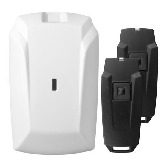
tion, operating conditions and maintenance of the Astra-R wireless
alarm system (fig. 1).
List of abbreviations:
RVC – wireless receiver Astra-RVC;
TRC – wireless transmitter Astra-TRC (keyfob);
CP – control panel «Astra-712/Х» or analog;
1 Function
Wireless panic button system - transmitting
alarm signals from registered TRC via radio
channel to RVC and generating a notification
by triggering the built-in RVC relay.
Remote control of electrically operated
mechanisms - transmitting signals from regis-
tered TRC via radio channel to RVC and trig-
gering the built-in RVC relay to control mecha-
nisms (gates, barriers).
2 Components
2.1 RVC
2.1.1 RVC – standalone receiver intended for:
receiving the signals via radio channel from TRC, decoding
and identification of the received signal,
control of the built-in relay.
2.1.2 RVC supports up to 99 TRCs.
2.1.3 RVC supports 2 modes of radio:
mode 1 (work with TRC released until 2017),
mode 2 (increased wireless coverage range, work with TRC
released from 2017).
2.1.4 Power supply of the RVC is carried out from an external
stabilized power source "Astra-712/0" or similar.
2.2 TRC
2.2.1 TRC – small-sized radio transmitters (keyfobs) with autono-
mous power supply, designed to generate and transmit signals
when pressing a panic button.
2.2.2 TRC in order to avoid a discharge of the battery stops
transmitting 10 sec. after pressing the button, if the button remains
in the pressed state.
2.2.3 TRC supports 2 modes of radio:
mode 1 (work with RVC released until 2017),
mode 2 (increased wireless coverage range, work with RVC
released from 2017).
2.3
Wireless coverage range:
150 meters (in mode 1),
300 meters (in mode 2)
on a dry ground covered area, in the absence of powerful radio inter-
ference, interfering and reflecting radio waves of objects. Inside rein-
forced concrete buildings or in the presence of interference, the wire-
less coverage range can be reduced to 30 m.
«Astra-R»
Wireless alarm system
Operation Manual
3 Technical specifications
Operation frequency mode 1, MHz ..................................... 433.92
Operation frequency mode 2, MHz ...................................... 434.92
Technical specifications of RVC
Power supply voltage, V ......................................... from 10.5 to 15
Current consumption, mA, not more ............................................ 50
Max relay load voltage at 0.1 А, V ............................................. 100
Boot time, sec, not more ............................................................. 10
Overall dimensions, mm ............................................ 101 × 63 × 32
Weight, kg, not more ................................................................ 0,07
Technical specifications of TRC
Power supply voltage, V from battery CR 2430, V, not more ......... 3
Transmitting power, mW, not more ............................................. 10
RVC
Current consumption:
- in standby mode, μA, not more ................................................... 5
- in transmitting mode, mA, not more........................................... 45
Overall dimensions, mm .............................................. 74 × 33 × 14
Weight, kg, not more ................................................................ 0,03
Operation conditions
Temperature range of RVC,
Temperature range of TRC,
TRC
Relative humidity, ............................................ .up to 95 at + 35 C
Figure 1
4 Delivery set
Wireless transmitter Astra-TRC (keyfob) ................................ 2 pcs.
Wireless receiver Astra-RVC .................................................... 1 pcs.
Screw ..................................................................................... 2 pcs.
Dowel .................................................................................... 2 pcs.
Operation manual ................................................................. 1 copy.
Note – TRС added in RVC's memory
5 Construction
5.1 RVC
5.1.1 Structurally, the RVC is made in the form of a unit consisting
of a base and a removable cover. A PCB with radio elements and
a built-in antenna is mounted inside the unit (fig. 2).
5.1.2 On the board there are green and red indicators for monitor-
ing the operation of the radio control room and indication of
broadcasting.
Mounting
holes
Tamper
control
Plugs
Jumpers
PCB
Holes for
wire entry
1
о
С ..................................from 0 to + 50
о
С ................................ .from 0 to + 50
without moisture condensation
.
Antenna
ANT plug
RF
GND
ANT
T MP
F 1
F 2
F 3
F 4
F5
OUT
T MP
+12V
GND
COM NO
Terminals
Fig.
2
Green
led
Red
led
Base
R-v11_5_en
Advertisement
Table of Contents

Subscribe to Our Youtube Channel
Related Manuals for teko Astra-R


Summary of Contents for teko Astra-R
- Page 1 Operation Manual This operating manual is intended to study the principle of opera- 3 Technical specifications tion, operating conditions and maintenance of the Astra-R wireless Operation frequency mode 1, MHz ........433.92 alarm system (fig. 1). Operation frequency mode 2, MHz ........434.92...
- Page 2 5.1.3 The board has screw terminal blocks: 6.2 TRC Terminal Function Table 2 – TRC indication Not used Notification Red led on TRC ТМP RVC tampering, relay opens when tampering Pushing the panic Lights up 1 time for 1 sec button + 12V, GND Power supply...
- Page 3 Press TMP button on RVC’s PCB and, while holding it, turn 9 Configuring on the power supply of the RVC, while the red led will light up. Release the TMP button on the RCV, while the red led turn off. 9.1 RVC and TRC after transportation under conditions different Wait for the required (programmable) time interval (from 2 s to from the operating conditions, keep unpacked under operating...
- Page 4 13.1.2 The wires of the power supply circuits, relay and TMP cir- Manufacturer: cuits, the interface line of the RVC should be located away from TEKO-TD LLC power and high-frequency cables. Prospekt Pobedy str. 19 13.1.3 RVC is not recommended to place: 420138 Kazan, Russia ...
Need help?
Do you have a question about the Astra-R and is the answer not in the manual?
Questions and answers