
Related Manuals for horsch Cultro 18 TC


Summary of Contents for horsch Cultro 18 TC
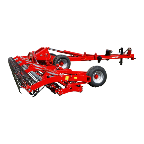
- Page 1 OPERATING INSTRUCTIONS Cultro 18 TC TRANSLATION OF THE ORIGINAL OPERATING INSTRUCTIONS READ CAREFULLY PRIOR TO STARTING UP! KEEP OPERATING INSTRUCTIONS IN A SAFE PLACE! ART.: 60021526 ISSUE: 06/2020...
- Page 3 HORSCH: ..............Confirmation of receipt of machinery Warranty claims become only effective when the first use of the machine is reported to HORSCH Maschinen GmbH within a week. www.horsch.com under SERVICE PARTNERBEREICH an interactive PDF form is available for down- load for this purpose (not available in all languages).
- Page 4 HORSCH Maschinen GmbH Sitzenhof 1, D-92421 Schwandorf erklärt hiermit in alleiniger Verantwortung als Hersteller, dass das nachfolgend genannte Produkt: Bodenbearbeitungsgerät Cultro 12 TC Typ: Cultro 18 TC den einschlägigen grundlegenden Sicherheits- und Gesundheitsanforderungen der Richtlinie 2006/42/EG entspricht. Schwandorf, 10.06.2020 Klaus Winkler Dokumentationsbevollmächtigter...
-
Page 6: Table Of Contents
Table of contents Introduction ...........4 Operation .............30 Foreword ............4 Commissioning / Tractor change ....30 Notes on representation .........4 Adjusting the drawbar eye Service............5 (workshop work) ........30 Warranty claim processing ......5 Connecting/Parking ........30 Consequential damage........5 Connecting ...........30 Transport position .........31 Safety and responsibility ......6 Parking ............33 Intended use ...........6 Folding ............34... -
Page 8: Introduction
DANGER to the safety notes! Highlights a danger that will lead to death or HORSCH will not assume liability for any dam- severe injury if it is not avoided. age or malfunctions resulting from failure of complying with the operating instructions. -
Page 9: Service
Service Consequential damage HORSCH Company would like you to be com- The machine has been manufactured by pletely satisfied with your machine and our HORSCH with greatest care. However, despite services. the intended use deviations in placing quantity up to total failure may be caused by e.g.: If you encounter any problems, please feel free to contact your sales partner. -
Page 10: Safety And Responsibility
Please read and comply with the following safety are considered not as intended. notes, before you start to use the machine! HORSCH does not assume any liability for Intended use damages resulting from the unintended use of the machine. -
Page 11: Qualification Of Personnel
The person is acquainted with the function of ¾ service personnel from HORSCH. This refers to the machine within the scope of its work and the following activities: is able to assess and avoid any work related dangers. -
Page 12: Children In Danger
Children in danger Safety in traffic Children are not able to assess dangers and may DANGER behave unpredictably. Children are therefore especially endangered: No passengers are allowed to ride on the machine! Keep children away from the machine. ¾ Especially before driving off and before trig- ¾... -
Page 13: Safety In Operation
Have damage, that could affect safety and ¾ after receiving instructions by employees of that cannot be rectified by yourself, rectified the authorized dealer or a HORSCH em- by a qualified expert workshop. ployee. Send the acknowledgement of receipt per ¾... - Page 14 Coupling and uncoupling In the case of injury, contact a doctor imme- ¾ diately! Faulty coupling of the machine to the pulling tool Secure and lock the control unit on the tractor ¾ of the tractor causes dangers, which could result if not in use! in severe accidents.
- Page 15 Use in the field Warn persons: DO NOT come near the ma- ¾ chine. Electric voltages at the ground can cause severe electric shock. DANGER Wait for professional rescuers. The overhead ¾ No passengers are allowed to ride on the power line needs to be switched off.
-
Page 16: Fertiliser And Dressed Seed
Caution! Danger of injury caused by projecting ¾ claim. parts (e.g. coulters)! Assume ergonomic working postures with any HORSCH is not liable for damages to life and ¾ assembly work. limb as well as property damages resulting from unapproved retrofitting and conversions. -
Page 17: Care And Maintenance
Care and maintenance by an operator who has been trained by HORSCH for this purpose. Inappropriate care and maintenance put the operational safety of the machine at risk. This can lead to accidents with severe or even fatal physical injuries. -
Page 18: Danger Zone
Danger zone Failing to pay attention to the danger zone can The area marked red indicates the danger zone result in severe or even fatal physical injuries. of the machine: Do not stand under lifted loads. Lower such ¾ loads to the ground first. Instruct persons to leave the danger zone ¾... -
Page 19: Safety Stickers
Safety stickers Safety stickers on the machine warn of hazards Clean soiled safety stickers. ¾ at dangerous points and are an important part Damaged or illegible safety stickers must be ¾ of the safety equipment of the machine. Miss- replaced immediately. ing safety stickers increase the risk of severe or Affix the specified safety stickers on spare ¾... - Page 20 Secure the machine with wheel Staying in the danger zone is chocks before uncoupling or only permitted when the lifting parking. cylinder pin is inserted. 00380896 00381116 Remaining in the danger zone Keep sufficient safety distance is only permitted if the safety to the slewing range of the support is in place.
-
Page 21: Commissioning
If the machine is hitched up in two-point mode, ¾ These work activities may be carried out only by the tractor link arms must be blocked against persons trained by HORSCH for this purpose. swinging sideways. On a trailer or low loader the machine must ¾... -
Page 22: Technical Data
Data on the type plate: 1 Model designation Sitzenhof 1 Made in Germany 2 Serial number D-92421 Schwandorf Maschinen GmbH www.horsch.com 3 Year of construction 4 Vehicle class 5 Type approval number A-0: 6 Vehicle identification number (VIN) A-1: A-2:... - Page 23 Cultro 18 TC 8580 2905 2950 11020 8580 1090 10790 8580 1090 12760 10790 1: 1 00 12760 1: 1 00 1: 1 00 Nummer 100933496 Ersteller Maßeinheit Teilezeichnung Erstellt am 24.03.20 Maßstab 1:50 Seitenzahl 2 / 2 © HORSCH Urheberschutz: Für diese technische Unterlage...
-
Page 24: Requirements For The Tractor
The tractor must meet the following require- ments to be able to use the machine as intended: Implement attachment Cultro 18 TC Adjustable drawbar Drawbar eye ø 42 mm (Cat. III) Adjustable drawbar Drawbar eye ø 46 mm (Cat. III) Adjustable drawbar Drawbar eye ø... - Page 25 Hydraulics Maximum system pressure 210 bar Oil grade Mineral hydraulic oil Delivery rate 80 l/min at 150 bar Number of dual-acting control units Brake connections Pneumatic brake Red connection for supply line Yellow connection for brake line...
-
Page 26: Calculating The Ballasting
Calculating the ballasting Required data: The permissible total weight, the permissible axle loads and the load bearing capacity of the tyres must not be exceeded when mounting or hitching up implements. The front axle of the tractor must always be loaded with at least 20 % of the curb weight of the tractor. - Page 27 1. Calculation of minimum front ballasting 4. Calculation of the actual total weight with rear implement: • (c + d) - T • b + 0.2 • T • b Enter the result of the calculated total weight and a + b V min the permissible total weight from the operating instructions of the tractor into the table.
-
Page 28: Construction
Construction Overview Cultro 12 TC (variant with three-row harrow) 1 Attachment of drawbar eye 2 Support 3 Brake valve spring accumulator brake 4 Undercarriage 5 Support wheels 6 Cutting blade roller 7 Harrow 8 Lighting 9 Hydraulic cylinder Folding 10 Hydraulic cylinder Lift/Lower... -
Page 29: Hydraulics
Hydraulics Marking of hydraulic hoses Symbols on the handles of the hydraulic cou- plings indicate the function of the respective WARNING hoses: Unintentional hydraulic movements may lead to severe accidents and injuries! Secure or lock the control units on the tractor. ¾... - Page 30 1 mm 40 bar 1 mm 1 mm 1 mm 1 Hydraulic coupling Lift 12 Hydraulic cylinder Folding 2 Hydraulic coupling Lower 13 Pressure gauge Wing preload pressure 3 Hydraulic coupling Unfolding 14 Measuring port 4 Hydraulic coupling Folding 15 Pressure accumulator 5 Hydraulic coupling Increase working depth 16 Lock valve 6 Hydraulic coupling Reduce working depth...
-
Page 31: Lighting
Lighting NOTE The following hydraulic movements are carried out via the hoses marked with Lift • Folding • Retraction of cultivation tools • Fan flow • 7-pin plug Rear light, right Lamp, blinker Lamp, taillight Lamp, brake light Rear light, left Lamp, brake light Lamp, taillight Lamp, blinker... -
Page 32: Instruction Stickers
Instruction stickers Always plug in all hydraulic lines. Otherwise components could be damaged because of Clean soiled stickers. interconnected hydraulic functions. ¾ Damaged or illegible stickers must be re- ¾ placed immediately. Apply the specified stickers to spare parts. ¾ Retighten the wheel nuts / wheel bolts after 50 km or 10 hours. - Page 33 Loading hook; hook the load suspension gear (chains, ropes etc.) into this loading hook during loading. Loading work only by operators trained by HORSCH!
-
Page 34: Operation
Operation Connecting/Parking Whenever working on the machine DANGER pay attention to the associated safety notes in the chapter "Safety and Serious accidents when manoeuvring and cou- prevention of accidents" as well as pling! the accident prevention instructions! Keep an eye on your environment. ¾... -
Page 35: Transport Position
Transport position NOTE Check all plug-and-socket connections (hy- ¾ WARNING draulic, electric and pneumatic) for cleanli- ness and firm seating. Danger of road accidents caused by losing the Dirty connectors will contaminate the flowing machine or machine parts. media. The connectors therefore become Before driving off: worn and this results in malfunctions and failures in the connected assembly groups. - Page 36 Position of control units during road travel Position Floating position Locked position Control unit Unfolding / Folding Lift / Lower Cutting blade roller...
-
Page 37: Parking
Parking DANGER Serious accidents caused by the machine roll- ing away! Park the machine only on a flat, paved sur- ¾ face. Before unhitching secure the machine with ¾ the parking brake and wheel chocks. When unhitching machines with pneumatic ¾... -
Page 38: Folding
Folding Unfolding 1. Turn the lock valve to the Field position: WARNING Dropping or lowering machine parts can cause severe crushing injuries etc.! No persons may stay under raised machine ¾ parts! Order persons to leave the danger zone around ¾... -
Page 39: Folding
Cutting blade roller Folding 1. Lift the attachment block or the wings nearly The cutting blade roller crushes and splits up completely. long-stem harvest residues and catch crops. 2. Fold the cutting blade roller. The catching hooks must be above the draw- WARNING bar (see figure at Unfolding). -
Page 40: Harrow
Harrow Lift the machine. ¾ Extend the hydraulic cylinders completely. ¾ The machine is equipped with a harrow. Depending on the required incline of the har- ¾ rows, plug on aluminium clips on all hydraulic Harrow, 1-row cylinders (1). Plug on the same number and colour of clips The incline or aggressiveness of the harrow can on all hydraulic cylinders. -
Page 41: Packer
Packer In the working position the machine runs on the packer. Due to the weight of the machine high consolidation and a fine crumbly, level surface is achieved. With cohesive soils the packers may become blocked with soil and thus become considerably heavier. -
Page 42: Use In The Field
Use in the field Lower the cutting blade roller with pressure, ¾ see Cutting blade roller section. The packer should have contact with the ¾ NOTE ground during use. If necessary, reduce the pressure of the cutting blade roller, see Cutting The machine must be in horizontal position ¾... -
Page 43: Checks
Checks The working quality essentially depends on the adjustments and checks made prior to and dur- ing use, as well as on regular care and mainte- nance of the machine. Carry out all maintenance tasks and adjust- ¾ ments before starting to work. Checks before and during use on the field Have the hydraulic lines been connected... -
Page 44: Optional Equipment
Coupling head “Brake” yellow workshop or by an operator, who has been Coupling head “Provision” red specially trained by HORSCH for this purpose. Filter Trailer brake valve Air reservoir Drain valve Spring brake cylinder 1 Anschluß... - Page 45 The machine always needs to be secured with Clean the filter as required, but at least once ¾ the parking brake (2) to prevent it from rolling a year. away in case of a pressure loss in the service Check the brake lining for wear every year ¾...
-
Page 46: Care And Maintenance
Care and Cleaning Maintenance Perform regular cleaning and maintenance work in order to maintain the operability of the machine and to achieve optimal performance. WARNING NOTE Risk of injuries during maintenance work Do not clean hydraulic cylinders and bearings Please observe the safety notes on care and ¾... -
Page 47: Maintenance Intervals
Maintenance intervals The maintenance intervals are determined by various factors. Different application conditions, weather influ- ences, working speeds and soil conditions have an influence on the maintenance intervals. The quality of the lubricants and cleaning agents also affects the time to the next care activities. The specified maintenance intervals therefore only serve as a reference. -
Page 48: Maintenance Overview
Maintenance overview Cultro TC Maintenance location Work instructions Interval After 10 operating hours Retighten all screw and plug-in Even firmly tightened screw connections can come loose (e.g. Once connections as well as the hydraulic because of material settlement or paint residues between the connections. - Page 49 Maintenance location Work instructions Interval Drawbar eye Fastening ¾ Check mounting screws for firm seat (560 Nm) 40 h Wear ¾ Replace the component concerned if one of the wear limits 40 h has been exceeded or fallen short of (workshop work): Designation Nominal dimension Wear dimension...
- Page 50 Maintenance location Work instructions Interval Safety installations Lighting and warning boards Check condition and function daily Warning and safety stickers Check that they are in place and legible 40 h At the end of the season Complete machine Perform care and cleaning work; do not spray plastic parts with oil or similar Spray the piston rods of the hydraulic cylinder with a suitable corrosion protection agent Check all screw and plug-and-socket-connections for firm seating (see...
- Page 51 Lubrication points ( lubrication grease: DIN 51825 KP/2K-40) - Lubricate the following, number of lubrication points in brackets Lubricate brake shaft lubricate (6) 40 h Cutting blade roller joints lubricate (8) 40 h Wing joints lubricate (4) 40 h Lift/lower joints lubricate (2) 40 h Lubrication points with the addition "2x"...
-
Page 52: Waste Disposal
Attention must be paid to all valid regulations. Decommissioning and waste disposal must only be carried out by operators who have been trained by HORSCH. Contact a waste disposal company, if this should be necessary. -
Page 53: Appendix
Appendix Tightening torques NOTE The tightening torques only serve as guidelines and are generally valid. Actual data given at the • corresponding points in the operating instructions have priority. Screws and nuts must thereby not be treated with lubricant, since this would change the friction value. •... - Page 54 Inch screws Tightening torques - inch screws in Nm Screw Strength 2 Strength 5 Strength 8 diameter No marks on head 3 marks on head 6 marks on head Inch Coarse Fine thread Coarse Fine thread Coarse Fine thread thread thread thread 12.2...
-
Page 55: Index
Index Length 18 Accessories 6 Liability 4 Adjustable drawbar 20 Lighting 27 Lubrication 42 Lubrication points 47 Ball head 20 Brake 40 Brake system 45 Maintenance 13,42,44 Brake valve 41 Maximum speed 9,18 Cable 27 Operator 7 Care 13,42 Overhead lines 10 Children 8 Cleaning 42 Commissioning 17,30... - Page 56 Technical data 18 Tractor change 30 Traffic 8 Transport 8 Transport height 18 Transport position 31 Transport width 8,18 Type approval 9 Type plate 18 Unfolding 34 Use in the field 11,38 Warranty 4 Waste disposal 48 Weight 18 Wheel nuts 44 Wheels / brakes 45 Width 18 Working width 18...
- Page 58 All details on technical specifications and pictograms are approximate and for information only. Subject to technical product revisions. HORSCH Maschinen GmbH Tel.: +49 94 31 7143-0 Sitzenhof 1 Fax: +49 94 31 7143-9200 92421 Schwandorf E-Mail: info@horsch.com www.horsch.com...
Need help?
Do you have a question about the Cultro 18 TC and is the answer not in the manual?
Questions and answers