DIEL AT200 Installation And Instruction Manual
Hide thumbs
Also See for AT200:
- Installation and instruction manual (32 pages) ,
- Manual (46 pages) ,
- Installation and instruction manual (46 pages)
Table of Contents
Advertisement
Available languages
Available languages
Quick Links
Advertisement
Table of Contents

Related Manuals for DIEL AT200


Summary of Contents for DIEL AT200
- Page 1 AT200 MANUALE DI INSTALLAZIONE ED USO INSTALLATION AND INSTRUCTIONS MANUAL...
- Page 3 ITALIANO MONTAGGIO Eseguire nel pannello un foro da 91X91 mm, fissare la centralina con i ganci in dotazione. ALIMENTAZIONE E COLLEGAMENTI ELETTRICI Morsetti 1-2-3: Collegamento per 2 sonde PTC, morsetto 1 sonda PTC1, morsetto 2 sonda PTC2, morsetto 3 comune. Morsetti 4-5: Controllo remoto, alla chiusura del contatto, in caso di funzionamento automatico, si abilitano...
-
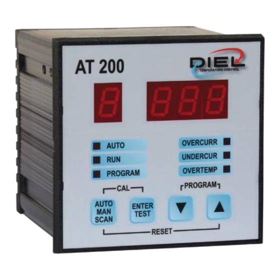
Page 4: Pannello Frontale
ITALIANO Morsetti 12-13-14: alimentazione centralina AT100, con tensione alternata (220÷240 ±10% V AC 50-60 Hz). Morsetto 15-16-17: Uscita Motore 2, controllo e comando della seconda linea di ventilazione (max 5A 220÷240 ±10% V AC 50-60 Hz). PANNELLO FRONTALE Visualizza la funzione o il canale e il relativo valore in esecuzione Segnala il funzionamento... - Page 5 RESET: Effettua il reset degli allarmi >> Paragrafo FUNZIONE RESET FUNZIONAMENTO DELLA CENTRALINA La centralina AT200 serve a monitorare le correnti assorbite di due linee indipendenti di ventilazione e, dopo un processo di taratura iniziale, segnalare situazioni di eccessivo o ridotto assorbimento di corrente.
- Page 6 ITALIANO FUNZIONE CAL Si accede con la pressione contemporanea e prolungata di entrambi i tasti, ed effettua l’auto calibrazione della centralina con lettura e memorizzazione delle correnti assorbite dai ventilatori come riferimento per la gestione degli allarmi. Il funzionamento è totalmente automatico in tutte le sue fasi per una durata massima di circa 2 minuti.
-
Page 7: Funzione Reset
ITALIANO UTILIZZO SENSORI PTC: Abilitazione degli ingressi per i sensori PTC: 0 = Non abilitati, 1 = Abilitati (Default = 0) SCOSTAMENTO CORRENTE: Scostamento percentuale della corrente attuale rispetto a quella di calibrazione. Un valore rilevato oltre questa soglia commuta il relè di FAULT. (Default = 10 %.) DELAY INIZIALE: Impostazione del tempo dopo lo start dei ventilatori prima di analizzare eventuali allarmi.(Default =... - Page 8 ITALIANO SET CORRENTE: Indica il SET iniziale memorizzato in sede di calibrazione, premendo UP il valore relativo al canale 1. SOVRACORRENTE: Indica massima sovracorrente raggiunta, premendo UP, il relativo valore al canale 1 SCOSTAMENTO CORRENTE: ==>> FUNZIONE PROGRAM=> SCOSTAMENTO CORRENTE DELAY INIZIALE: ==>>...
- Page 9 ITALIANO MANUALE: I ventilatori saranno accesi e spenti manualmente dall’operatore. Il Display indicherà la sigla iniziale MAN ed il led AUTO rimarrà spento. Per comandare l’accensione dei ventilatori 1 e 2 premere il tasto ENTER/ TEST, il led PROGRAM lampeggierà, e verrà proposto il ventilatore 1, con i tasti UP/DOWN commutare in on/off, premere nuovamente il tasto ENTER/TEST per passare al ventilatore 2, con i tasti UP/DOWN commutare in on/off.
-
Page 10: Caratteristiche Elettriche
ITALIANO CARATTERISTICHE ELETTRICHE • Contenitore 90X90X130 mm incluse morsettiere. • Pannello frontale 96x96 mm. • Peso 0.5 Kg. • Contenitore in ABS auto estinguente. • Alimentazione 220÷240 ±10% V AC 50-60 Hz. • Collegamenti elettrici su morsettiere estraibili polarizzate. • Rilevamento e controllo della corrente assorbita dai motori dei ventilatori su due linee indipendenti. -
Page 11: Power Supply And Electrical Connections
ENGLISH ASSEMBLY Make a hole of 91X91 mm in the panel, attach the control unit using the supplied hooks. POWER SUPPLY AND ELECTRICAL CONNECTIONS Terminals 1-2-3: Connection for 2 PTC probes, terminal 1 PTC1 probe, terminal 2 PTC2 probe, terminal 3 common. Terminals 4-5: Remote control upon closing of the contact, in case of automatic operation the ventilation lines... -
Page 12: Front Panel
ENGLISH Terminal 12-13-14: power supply to AT100 control unit, with alternating voltage (220÷240 ±10% V AC 50-60 Hz). Terminal 15-16-17: Motor 2 Output, monitoring and control of the second line of ventilation (max 5A 220÷240 ±10% V AC 50-60 Hz). FRONT PANEL Displays the function or the channel and the relative... - Page 13 RESET: Resets the alarms >> Section RESET FUNCTION THE OPERATION OF THE CONTROL UNIT The control unit AT200 monitors the current consumption of two independent lines of ventilation and, after the initial calibration procedure, reports excessive or reduced current consumption situations.
-
Page 14: Cal Function
ENGLISH CAL FUNCTION Activate it by pressing and holding both buttons simultaneously; it runs the auto calibration of the control unit, reading and saving the current consumption of the fans to use as reference for alarm management. The operation is completely automatic in all its phases for a maximum period of about 2 minutes. -
Page 15: Reset Function
ENGLISH HOW TO USE THE PTC SENSORS: Enabling inputs for PTC sensors: 0 = Disabled, 1 = Enabled (Default = 0) CURRENT OFFSET: Measured offset value of the current, expressed as a percentage, compared to set point. If the value measured exceeds this threshold, the FAULT relay will be triggered. -
Page 16: Initial Delay
ENGLISH MAX SURGE CURRENT: Indicates the maximum overcurrent reached, pressing UP, the value corresponding to channel 1 CURRENT OFFSET: ==>> PROGRAM FUNCTION=> CURRENT OFFSET INITIAL DELAY: ==>> PROGRAM FUNCTION=> INITIAL DELAY ALARM DELAY: ==>> PROGRAM FUNCTION=> ALARM DELAY HOW TO USE THE PTC SENSORS: ==>>... - Page 17 ENGLISH SCAN: Fans are switched on and off via a remote system (i.e. MT200 control unit) connected to terminals 4 and 5. The Display will show the initial acronym SCAN and the AUTO LED will flash. The display alternately and automatically shows the values of channel 1 and those of channel 2.
-
Page 18: Electrical Properties
ENGLISH ELECTRICAL PROPERTIES • Container 90X90X130 mm, including the terminals. • Front panel 96x96 mm. • Weight 0.5 Kg. • ABS self extinguishing container. • Power supply (220÷240) Volt AC ± 10% 50/60 Hz. • Electrical connections on removable polarized terminals. •... - Page 19 TAB 1...
- Page 24 Diel srl Via A. Pizzocaro, 9 - 36075 MONTECCHIO MAGGIORE (VI) ITALY Tel +39 0444 440977 - Fax +39 0444 448728 mail: info@diel-ed.it - www.diel-ed.it 2018_01...
Need help?
Do you have a question about the AT200 and is the answer not in the manual?
Questions and answers