DIEL AT200 Installation And Instruction Manual
Hide thumbs
Also See for AT200:
- Installation and instruction manual (25 pages) ,
- Manual (46 pages) ,
- Installation and instruction manual (46 pages)
Table of Contents
Advertisement
Available languages
Available languages
Quick Links
Advertisement
Table of Contents

Subscribe to Our Youtube Channel
Related Manuals for DIEL AT200


Summary of Contents for DIEL AT200
- Page 1 AT200 MANUALE DI INSTALLAZIONE ED USO INSTALLATION AND INSTRUCTIONS MANUAL...
-
Page 3: Table Of Contents
AT 200 INDICE INFORMAZIONI DI SICUREZZA FUNZIONAMENTO DELLA CENTRALINA CARATTERISTICHE ELETTRICHE PRECAUZIONI NORME DI GARANZIA MONTAGGIO ALIMENTAZIONE E COLLEGAMENTI ELETTRICI PANNELLO FRONTALE SET AUTO/MAN/SCAN FUNZIONE TEST DISPLAY PROGRAMMAZIONE RESET CALIBRAZIONE VISUALIZZAZIONE VALORI ERRORI VISIONE CENTRALINA (TAB 1) - 3 -... -
Page 4: Informazioni Di Sicurezza
ADEGUATAMENTE FORMATO. FUNZIONAMENTO DELLA CENTRALINA La centralina AT200 serve a monitorare le correnti assorbite di due linee indipendenti di ventilazione e, dopo un processo di taratura iniziale, segnalare situazioni di eccessivo o ridotto assorbimento di corrente. È dotata anche di due ingressi PTC per rilevare la temperatura dei motori dei ventilatori. -
Page 5: Precauzioni
AT 200 • Relè fault 250 V AC, 5 A massimi (carico resistivo), 1 contatto pulito di scambio. • Motore Ventilatore 1: max. 5A 220 ÷ 240 Volt AC ±10% 50-60Hz. • Motore Ventilatore 2: max. 5A 220 ÷ 240 Volt AC ±10% 50-60Hz. Caratteristiche •... -
Page 6: Norme Di Garanzia
AT 200 trasformatore, si presentino sovratensioni che possono danneggiare l'apparecchiatura. Questo è tanto più evidente se la tensione di alimentazione della centralina, è di 230 V AC e se esistono condensatori di rifasamento. NORME DI GARANZIA La centralina è coperta da garanzia per un periodo di 3 anni dalla data di collaudo posta sia sull’etichetta che sul manuale allegato. -
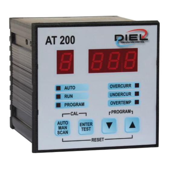
Page 7: Pannello Frontale
(max. 5A 220÷240 ±10% V AC 50-60 Hz). Morsetti 12-13-14: alimentazione centralina AT200, con tensione alternata (220÷240 ±10% V AC 50-60 Hz). Morsetti 15-16-17: Uscita Motore Ventilatore 2, controllo e comando della seconda linea di ventilazione (max. - Page 8 AT 200 Segnala Manual funzionamento automatico (acceso), Auto manuale (spento), scansione (lampeggiante). Scan >> Paragrafo SET AUTO/MAN/SCAN Segnala che almeno un ventilatore è in marcia. Segnala centralina è menu programmazione. >> Paragrafo PROGRAMMAZIONE Segnala assorbimenti di correnti superiori al set di calibrazione iniziale in almeno un canale (lampeggiante).
-
Page 9: Set Auto/Man/Scan
AT 200 Consente commutazione funzioni AUTOMATICA, MANUALE e SCANSIONE. >> Paragrafo SET AUTO/MAN/SCAN Enter: In fase di programmazione consente la conferma di un dato inserito. Test: Consente il test dei display e del relè. >> Paragrafo FUNZIONE TEST DISPLAY TASTI DI NAVIGAZIONE: Consentono lo scorrimento delle diverse pagine di menu e l'incremento decremento dei valori di programmazione. - Page 10 AT 200 altrimenti sarà visualizzato il canale con assorbimento più alto e alternativamente lo scostamento percentuale rispetto al valore di calibrazione. Con i tasti è possibile vedere l’altro canale (se abilitato), dopo di che la centralina tornerà a mostrare il canale con assorbimento più...
-
Page 11: Funzione Test Display
AT 200 lampeggiante. Se il comando remoto è assente verrà visualizzata scritta , altrimenti verranno visualizzati alternativamente ed in modo automatico i valori di tutti i canali abilitati. FUNZIONE TEST DISPLAY TEST DISPLAY: premere il tasto , verranno accesi tutti i led ed i display per qualche secondo. Il test display viene effettuato ad ogni accensione della centralina. -
Page 12: Reset
AT 200 DELAY INIZIALE: Impostazione del tempo dopo lo start dei ventilatori prima di analizzare eventuali allarmi. Durante questo tempo i canali saranno visualizzati così (Default = 10 sec.) DELAY ALLARME: Impostazione del tempo di permanenza errore prima di attivare un allarme. (Default = 5 sec.) CANALE 1: Abilitazione della gestione del canale 1: 0 = Non abilitato, 1 = Abilitato. -
Page 13: Calibrazione
AT 200 RESET DEFAULT: Premere contemporaneamente i tasti per: Resettare gli allarmi Ripristinare le impostazioni di fabbrica (PTC=0, P=10, d=10, E=5, CH1=1, CH2=1) CALIBRAZIONE Si accede con la pressione contemporanea e prolungata di entrambi i tasti, ed effettua l'auto calibrazione della centralina con lettura e memorizzazione delle correnti assorbite dai ventilatori come riferimento per la gestione degli allarmi. - Page 14 AT 200 pressione la centralina torna a visualizzare i canali. SET CORRENTE: Indica il SET iniziale memorizzato in sede di calibrazione, premendo vengono visualizzati i valori relativi ai canali abilitati. MAX SOVRACORRENTE: Indica la massima sovracorrente raggiunta, premendo vengono visualizzati i valori relativi ai canali abilitati.
-
Page 15: Errori
AT 200 ERRORI OVERCURRENT: Indica assorbimenti corrente superiori rispetto ai valori rilevato in sede di calibrazione. Il relè FAULT commuta. La linea di ventilazione viene arrestata e il rispettivo canale viene visualizzato così UNDERCURRENT: Indica assorbimenti di corrente inferiori rispetto ai valori rilevati in sede di calibrazione. - Page 16 AT 200 INDEX SAFETY INFORMATION CONTROL UNIT OPERATION ELECTRICAL CHARACTERISTICS PRECAUTIONS WARRANTY RULES ASSEMBLY POWER SUPPLY AND ELECTRICAL CONNECTIONS FRONT PANEL SET AUTO/MAN/SCAN DISPLAY TEST FUNCTION PROGRAMMING RESET CALIBRATION VALUES DISPLAY ERRORS CONTROL UNIT VIEW (TAB 1) - 16 -...
- Page 17 THIS MANUAL IS INTENDED FOR TECHNICAL STAFF ADEQUATELY TRAINED. CONTROL UNIT OPERATION AT200 control unit monitors current consumption of two independent lines of ventilation and, after initial calibration procedure, reports excessive or reduced current consumption situations. It also features two PTC inputs to measure fan’s motors temperature.
- Page 18 AT 200 • Fan motor 1: max. 5A 220 ÷ 240V AC ±10% 50-60Hz. • Fan motor 2: max. 5A 220 ÷ 240V AC ±10% 50-60Hz. Characteristics • Self-extinguishing NORYL container. • Front panel protection grade in polycarbonate: IP65 (IP66 on request). •...
- Page 19 AT 200 WARRANTY RULES The control unit is covered by a warranty for a period of 3 years from the test date placed both on the label and on the attached manual. The warranty is considered valid when it has been ascertained that the causes of the fault are attributable to manufacturing defects.
- Page 20 AT 200 ASSEMBLY Make a 91X91 mm hole in the panel, fix the control unit with the supplied hooks. POWER SUPPLY AND ELECTRICAL CONNECTIONS Terminals 1-2-3: Connection for 2 PTC probes, terminal 1 PTC2 probe, terminal 2 PTC1 probe, terminal 3 common.
- Page 21 AT 200 Terminals 12-13-14: power supply to AT200 control unit, with alternating voltage (220÷240 ±10% V AC 50-60 Hz). Terminals 15-16-17: Fan Motor 2 Output, monitoring and control of the second line of ventilation (max. 5A 220÷240 ±10% V AC 50-60 Hz).
- Page 22 AT 200 It reports current consumptions lower than initial set points on at least one channel (blinking). Alarm >> Paragraph ERRORS It indicates over temperature fault in at least one fan motor (blinking). Alarm >> Paragraph ERRORS It enables switching between the AUTOMATIC, MANUAL and SCAN functions.
- Page 23 AT 200 SET AUTO/MAN/SCAN Press the button to select the operation between AUTOMATIC, MANUAL, SCAN. AUTOMATIC: Fans are switched on and off via remote system (e.g. MT200 control unit) connected to terminals 4 and 5. The display will show the initial acronym AUT and the AUTO LED will lit.
- Page 24 AT 200 SCAN: Fans are switched on and off via remote system (e.g. MT200 control unit) connected to terminals 4 and 5. The display will show the initial acronym SCAN and the AUTO LED will flash. If remote control absent, message will displayed, otherwise the display alternately and automatically shows channel 1 and...
- Page 25 AT 200 CURRENT OFFSET: Value offset admitted of the current, expressed as percentage, compared calibration currents. If the values measured exceed this threshold, the FAULT relay will be triggered. (Default = 10 %) INITIAL DELAY: Time after the start of the fans before analysing any alarms.
- Page 26 AT 200 interrupted and not saved (therefore the previously set parameters remain active) after which it returns to automatic display mode. RESET RESET ALARMS: Simultaneously press the keys to reset the alarms. RESET DEFAULT: Simultaneously press the keys Reset the alarms Restore factory settings (PTC=0, P=10, d=10, E=5, CH1=1, CH2=1) CALIBRATION...
- Page 27 AT 200 VALUES DISPLAY By pressing the navigation keys, you can always view the values measured by the controller. After a few seconds after the last pressure the control unit returns to display the channels. CURRENT SET: It indicates the initial SET stored upon calibration, pressing the values for the enabled channels are displayed.
- Page 28 AT 200 ERRORS OVERCURRENT: indicates that current consumptions are greater than the value measured during calibration. The FAULT relay switches. Ventilation line stops and the respective channel is displayed like this UNDERCURRENT: Indicates that current consumptions are lower than the value measured during calibration.
-
Page 29: Visione Centralina (Tab 1)
TAB 1 VISIONE CENTRALINA (TAB 1) CONTROL UNIT VIEW (TAB 1) - 29 -... - Page 30 NOTES - 30 -...
- Page 31 - 31 -...
- Page 32 Diel S.r.l. Via A. Pizzocaro, 9 - 36075 MONTECCHIO MAGGIORE (VI) ITALY Tel +39 0444 440977 - Fax +39 0444 448728 info@diel-ed.it - www.diel-ed.it...
Need help?
Do you have a question about the AT200 and is the answer not in the manual?
Questions and answers