
Related Manuals for DIEL ME100 V3


Summary of Contents for DIEL ME100 V3
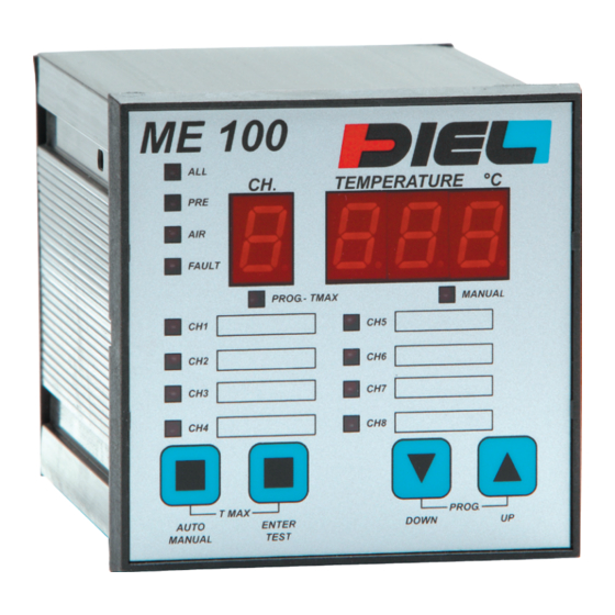
- Page 1 TEMPERATURE CONTROL ME100 V3 RS 422-485 – MODBUS-RTU MANUALE DI INSTALLAZIONE ED USO INSTALLATION AND INSTRUCTIONS MANUAL MANUAL DE INSTALACIÓN Y USO...
-
Page 3: Caratteristiche Tecniche
ITALIANO CARATTERISTICHE TECNICHE • Contenitore 90X90X135 mm incluse morsettiere. • Pannello frontale 96x96 mm. • Peso 0,6 Kg. • Contenitore in ABS auto estinguente. • Alimentazione universale (24÷240) Volt AC/DC ± 10% 50/60 Hz senza rispetto della polarità. • Collegamenti elettrici su morsettiere estraibili polarizzate. • Otto ingressi analogici, rilevamento e controllo della temperatura con sensori PT100 a tre fili nel range da -10 a +200 °C. -
Page 4: Collegamenti Elettrici
Eseguire nel pannello un foro da 91X91 mm, fissare la centralina con i ganci in dotazione. ALIMENTAZIONE La centralina ME100 V3 può essere alimentata con (24÷240) Volt AC/DC ±10% 50-60 Hz senza rispetto di polarità. I morsetti di alimentazione sono riportati in tabella (TAB 1) alla fine del manuale. - Page 5 ITALIANO Porta seriale RS485 full duplex: • Trasmissione: positivo TX+ morsetto 25. • Trasmissione: negativo TX- morsetto 26. • Ricezione: negativo RX- morsetto 27. • Ricezione: positivo RX+ morsetto 28. Per un corretto utilizzo della porta seriale collegare due resistenze di terminazione linea da 120 ohm in parallelo ai morsetti di ricezione posti fisicamente agli estremi della linea dati.
- Page 6 ITALIANO Le scritte che compaiono sul display a tre cifre assumono il seguente significato: ICF: sonda PT100 in avaria (interruzione connessione oppure assenza del sensore). SCF: sonda PT100 in avaria (corto circuito). rES: azzeramento memoria guasto sonde avvenuto. FAn: ventilazione relativa ad uno specifico canale. CH(n): stato di uno specifico canale n (1-8).
- Page 7 ITALIANO una sola soglia di accensione e spegnimento ventilazione valida per tutti i canali, controllo ventilazione anche a tempo (parametro t). Con F=2 oltre ai parametri impostati con F=1 si imposta il parametro t in minuti cioè il tempo in minuti che deve restare comunque attiva la ventilazione prima di intervenire sullo spegnimento.
- Page 8 ITALIANO (dati ed indirizzo corretti) e la successiva trasmissione da parte del dispositivo, questo per permettere al sistema di supervisione di predisporsi per la ricezione. Il ritardo di default è 25 centesimi di secondo. Infine viene richiesto il parametro U che rappresenta l’indirizzo che individua univocamente il dispositivo nella rete;...
-
Page 9: Norme Di Garanzia
AUTO/ MANUAL fino al comparire della scritta rES sul display. NORME DI GARANZIA La centralina ME100 V3 é coperta da garanzia per un periodo di 3 anni dalla data di consegna. - Page 10 ITALIANO La garanzia è ritenuta valida quando è stato accertato che le cause del guasto sono imputabili a difetti di fabbricazione. Non si risponde invece per guasti dovuti ad errato cablaggio delle sonde o errata tensione di alimentazione (es. 400 Volt AC). Non si risponde in ogni caso per danni provocati dal mal funzionamento della centralina stessa.
-
Page 11: Technical Features
ENGLISH TECHNICAL FEATURES • Box 90x90X135 mm included terminal blocks. • Front panel 96X96 mm. • Weight 0,6 Kg. • Self-extinguishable ABS Box. • Power supply (24÷240) Volt AC/DC ± 10% 50/60 Hz without polarity respect. • Electrical connections on polarized fast connectors. • Eight analogical input, temperature control and monitoring by PT100 sensors from -10 °C to +200 °C. -
Page 12: Power Supply
Perform a square hole measuring 91x91 mm, fasten the device through the special hooks. POWER SUPPLY ME100 V3 can be supplied with (24÷240) Volt AC/DC ±10% 50/60 Hz without respect of polarity. Power supply connectors are indicated at the end of this manual on table (TAB 1). -
Page 13: Messages Description
ENGLISH • Send: negative TX- connector 26. • Reception: negative RX- connector 27. • Reception: positive RX+ connector 28. For a correct use of RS485 communication interface, connect two resistors 120 in parallel of receive connectors situated at the beginning and at the end of the data line. All transportation cables of the measurement signals must be absolutely: • be separated from the power ones. - Page 14 ENGLISH The words that appear on three digit display assume the following meaning: ICF: PT100 probe failure due to interruption or absence of probe. SCF: PT100 probe failure due to electrical short circuit. rES: memory resetting of the failure probe effected. FAn: fan referred to a specific channel and fan.
- Page 15 ENGLISH alarm valid for all channels, active fan cooling system with only one level valid for lighting H and switching off L. With F=1 is possible to set only four parameters: P, A, L, H. F=2: group of eight active channels, only one level for alarm and pre alarm valid for all channels, active fan cooling system with only one level valid for lighting H and switching off L, control of fan cooling system also with time parameter t.
-
Page 16: Data Visualization
It is possible in addition to set a delay d in 1/100 seconds between the end of reception of a valid command (data and address right) and the following ME100 V3 transmission, to permit to the supervisor system to put it in receive mode. -
Page 17: Communication Protocol Modbus-Rtu
ENGLISH the maximum temperatures is signalised through the LED PROG.- TMAX which is placed on the front-end panel. With the buttons UP and DOWN it is possible to see the historical maximum temperature achieved by all active channels. For exit push button AUTO/MANUAL. -
Page 18: Warranty Rules
ENGLISH WARRANTY RULES ME100 V3 has a warranty period time of three year from delivery date. The warranty is valid only whether damages are due to manufacturing defects. We aren’t liable for damages due to a wrong wiring of probes or to a wrong power supply voltage (for example 400 Volt AC). -
Page 19: Características Técnicas
• Visualización automática del valor y del número de la sonda relativos al canal más caliente. • Memoria de los máximos históricos alcanzados por cada canal. • Rigidez dieléctrica 2.5 KV CA por 60”. -
Page 20: Montaje
Realizar en el panel un orificio de 91X91 mm, fijar la centralita con los ganchos suministrados. ALIMENTACIÓN La centralita ME100 V3 podrá ser alimentada con (24÷240) voltios CA/CC ± 10% 50-60 Hz, sin importar la polaridad. Los bornes de alimentación se indican se encuentran en (TAB 1) al final del manual. - Page 21 ESPAÑOL • Transmisión: negativo TX- borne 26. • Recepción: negativo RX- borne 27. • Recepción: positivo RX+ borne 28. Para un buen uso del puerto serial, conectar dos resistencias de fin de línea de 120 ohmios en paralelo a los bornes de recepción ubicados físicamente en los extremos de la línea de datos.
- Page 22 ESPAÑOL ICF: sonda PT100 en avería (interrupción o ausencia de sonda). SCF: sonda PT100 en avería (cortocircuito). rES: puesta a cero de la memoria de la avería sondas efectuada. FAn: ventilación relativa a un canal específico. CH(n): estado de un canal específico n (1-8). PrE: relé...
- Page 23 ESPAÑOL Con F=2 además de los parámetros configurados con F=1 se configura el parámetro t en minutos es decir, el tiempo en minutos que debe permanecer activa la ventilación antes de intervenir en el apagado. Esto garantiza un tiempo mínimo de activación de la ventilación independientemente del valor configurado por el umbral F=3: programación independiente para cada canal de todos los umbrales de alarma, prealarma, encendido y apagado del ventilador;...
- Page 24 ESPAÑOL por parte del dispositivo, esto para permitir que el sistema de supervisión se prepare para la recepción. El retraso por defecto es de 25 centésimos de segundo. Por último, se solicita el parámetro U que representa la dirección que identifica inequívocamente el dispositivo en la red; el valor por defecto para la dirección es cero, se desaconseja por tanto utilizar esta dirección como dirección válida en la red a fin de evitar conflictos con otros dispositivos eventualmente presentes y que aún...
-
Page 25: Normas De Garantía
AUTO/ MANUAL hasta que aparezca el código rES en el display. NORMAS DE GARANTÍA La centralita ME100 V3 está cubierta por una garantía de 3 años a partir de la fecha de entrega. - Page 26 MONTECCHIO MAGGIORE (VI). ATENCIÓN No efectuar pruebas de rigidez dieléctrica o de descargas parciales en las máquinas eléctricas con la centralita conectada y, de ser posible, no conectar directamente la centralita al secundario del transformador que se desea proteger puesto que, al estar sin protección, podría ocurrir que al cerrar el interruptor aguas abajo...
- Page 27 TAB 1...
- Page 28 TAB 2 TYPE DATA RANGE READ ONLY Temperature channel 1 -1000 / +20000 READ ONLY Temperature channel 2 -1000 / +20000 READ ONLY Temperature channel 3 -1000 / +20000 READ ONLY Temperature channel 4 -1000 / +20000 READ ONLY Temperature channel 5 -1000 / +20000 READ ONLY Temperature channel 6...
- Page 29 TAB 2 READ WRITE Allarm channel 3 -1000 / +20000 READ WRITE Allarm channel 4 -1000 / +20000 READ WRITE Allarm channel 5 -1000 / +20000 READ WRITE Allarm channel 6 -1000 / +20000 READ WRITE Allarm channel 7 -1000 / +20000 READ WRITE Allarm channel 8 -1000 / +20000...
- Page 30 TAB 2 Register 49 Status channel 1 to 8: bit 0 to bit7 • Channel disable Channel enable Register 50 Status fault channel 1 to 8: bit 0 to bit7 • Normal status channel Fault Channel Register 51 Status relay pre alarm: bit 0 •...
- Page 32 TEMPERATURE CONTROL Diel srl Via A. Pizzocaro, 9 - 36075 MONTECCHIO MAGGIORE (VI) ITALY Tel +39 0444 440977 - Fax +39 0444 448728 mail: info@diel-ed.it - www.diel-ed.it 2017_1...
Need help?
Do you have a question about the ME100 V3 and is the answer not in the manual?
Questions and answers