Advertisement
Quick Links
Advertisement

Related Manuals for BCP SKY3885


Summary of Contents for BCP SKY3885
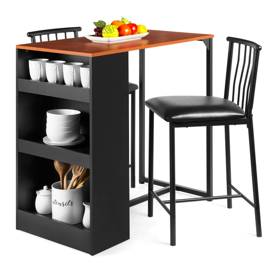
- Page 1 INSTRUCTION MANUAL 3-Piece Dinette Set with Storage Shelves SKY3885 + SKY6147 Ver. 3...
- Page 2 Fasten screws loosely during assembly. Do not firmly tighten screws until item is fully assembled. bestchoiceproducts.com...
-
Page 3: Tools Required
NOTICE Please retain these instructions for future reference. • Please do not exceed the weight limitations of this item. • Do not stand on or use any part of this item as a step ladder. • Firmly secure all bolts, screws and knobs before use. •... - Page 4 TABLE HARDWARE DOWEL CORNER BRACE 12 PCS 2 PCS TABLE PARTS SHELF SIDE I SHELF SIDE II SHELF SHELF SUPPORT I SUPPORT II 1 PC 1 PC 2 PCS 1 PC SHELF SHELF BACK TABLETOP SIDE FRAME PANEL 3 PCS 1 PC 1 PC 1 PC...
- Page 5 PRODUCT ASSEMBLY - TABLE Screw thirty-two part 1 cam bolts into the part A and B shelf sides, sixteen cam bolts per shelf side. Insert one part 5 dowel into the top of each shelf side.
- Page 6 PRODUCT ASSEMBLY - TABLE Locate three part E shelves and insert two part 5 dowels into each. Locate the part F shelf back panel and insert four part 5 dowels. Attach two part C and one part D shelf support to the part A shelf side with six part 2 cam locks.
- Page 7 PRODUCT ASSEMBLY - TABLE Attach three part E shelves with six part 2 cam locks.
- Page 8 PRODUCT ASSEMBLY - TABLE Attach the part F shelf back panel to the part A side panel with four part 2 cam locks.
- Page 9 PRODUCT ASSEMBLY - TABLE Attach the part B shelf side panel with sixteen part 2 cam locks. Set this shelf assembly aside.
- Page 10 PRODUCT ASSEMBLY - TABLE Attach two part 6 corner braces to the part H side frame with four part 3 screws. Attach two part I support beams to the side frame with four part 3 screws. Screw two part J feet into the side frame. Locate the part G tabletop and screw in six part 1 cam bolts, then attach the side frame assembly to the tabletop with four part 3 screws and three part 4 screws.
- Page 11 PRODUCT ASSEMBLY - TABLE Attach the shelf assembly to the tabletop with six part 2 cam locks, then attach the support beams with four part 3 screws. Flip the assembled table and adjust the part J feet until they are level.
- Page 12 CHAIR HARDWARE M6 X 45MM M6 X 25MM M6 X 20MM M6 X 12MM SCREW SCREW BOLT SCREW 16 PCS 4 PCS 4 PCS 4 PCS M6 SLEEVE 4 PCS CHAIR PARTS BACKREST BOTTOM FRONT SUPPORT SUPPORT 2 PCS 4 PCS 2 PCS 2 PCS SEAT...
- Page 13 PRODUCT ASSEMBLY - CHAIR Attach the part D2 seat support to two part B2 legs with two part 2A screws. Attach the leg assembly to the part A2 backrest with two part 3A bolts, two part 4A screws, and two part 5A sleeve nuts.
- Page 14 PRODUCT ASSEMBLY - CHAIR Attach the part C2 bottom support to the part B2 legs with four part 1A screws.
- Page 15 PRODUCT ASSEMBLY - CHAIR Attach the part E2 seat with four part 1A screws. Repeat to assemble a second chair.
-
Page 16: Help Center
HELP CENTER Question about your product? We're here to help. Visit us at: help.bestchoiceproducts.com CHAT Chat Support Product Inquiry Orders FAQ Product Assembly Returns & Refunds PRODUCT WARRANTY INFORMATION All items can be returned for any reason within 60 days of the receipt and will receive a full refund as long as the item is returned in its original product packaging and all accessories from its original shipment are included.
Need help?
Do you have a question about the SKY3885 and is the answer not in the manual?
Questions and answers