
Related Manuals for BCP SKY3079


Summary of Contents for BCP SKY3079
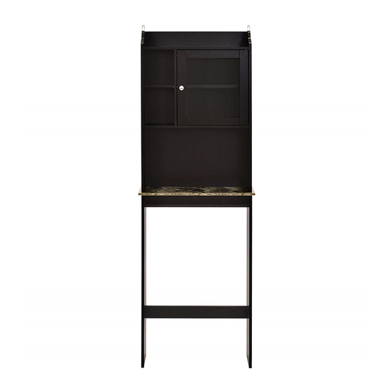
- Page 1 INSTRUCTION MANUAL Over-the-Toilet Bathroom Storage Cabinet SKY3079 + SKY3526 Ver. 2...
-
Page 2: Tools Required
NOTICE • Please do not exceed the weight limitations of this item. • Do not stand on or use any part of this product as a step ladder. • Firmly secure all bolts, screws and knobs before use. • Reconfirm that all bolts, screws, and knobs are secure every 90 days. •... - Page 3 HARDWARE 12MM CAM M4 X 35MM BRACKET M3 X 14MM LOCK SCREW SCREW 10 PCS 6 PCS 2 PCS 6 PCS M3.5 X 40vvMM WALL SCREW ANCHOR 2 PCS 2 PCS PARTS TOP PANEL MIDDLE SHELF I MIDDLE SHELF II LOWER SHELF 1 PC 1 PC...
- Page 4 PARTS RIGHT PANEL LOWER LOWER FRONT LEFT PANEL RIGHT PANEL SUPPORT 1 PC 1 PC 1 PC 1 PC BACK SUPPORT TOP SUPPORT BACK PANEL I BACK PANEL II 2 PCS 1 PC 1 PC 1 PC TIGHTENING CAMLOCKS Screw cam bolt Insert cam bolt and cam lock into Screw cam lock in completely.
- Page 5 PRODUCT ASSEMBLY Attach a part 7 knob to the part G door with a part 6 screw. Attach a part 8 metal plate with a part 9 screw. Insert a part 4 upper door hinge and part 5 lower door hinge. Screw a part 2 cam bolt into the part A top panel.
- Page 6 PRODUCT ASSEMBLY Screw six part 2 cam bolts into part H left panel and part I right panel. Screw six part 2 cam bolts into part J lower left panel and part K lower right panel.
- Page 7 PRODUCT ASSEMBLY Attach the lower panels to a part L front support and two part M back supports with six part 1 dowels and six part 13 cam locks. Attach the part F divider to part A top panel with two part 1 dowels and a part 3 cam lock.
-
Page 8: Product Assembly
PRODUCT ASSEMBLY Attach part D lower shelf with a part 1 dowel and two part 14 screws. Attach part N top support to part H left panel with a part 1 dowel and part 3 cam lock. - Page 9 PRODUCT ASSEMBLY Attach shelf assembly to left panel with four part 1 dowels and two part 3 cam locks. Slide in the part O back panel.
- Page 10 PRODUCT ASSEMBLY Attach part I right panel with five part 1 dowels and three part 3 cam locks. Slide in part P back panel.
- Page 11 PRODUCT ASSEMBLY Attach the part E bottom panel with four part 1 dowels and four part 14 screws. Screw in four part 2 cam bolts. Attach two part 15 brackets with six part 16 screws.
- Page 12 PRODUCT ASSEMBLY Attach the top assembly to the bottom assembly with four part 13 cam locks.
- Page 13 PRODUCT ASSEMBLY Install the part G door by angling the upper/lower hinges into the designated slots. NOTE: Insert the upper hinge before inserting the lower hinge.
- Page 14 PRODUCT ASSEMBLY Use a pencil and ruler to mark the desired mounting location. Drill two screw holes and insert two part 18 wall anchors into the holes. Attach the cabinet to the wall with two part 17 screws.
- Page 15 PRODUCT ASSEMBLY Insert eight part 11 shelf pegs. Place the part B and part C middle shelves on the pegs. NOTE: Insert the shelves at an angle.
-
Page 16: Help Center
HELP CENTER HELP CENTER Question about your product? We're here to help. Visit us at: Question about your product? We're here to help. Visit us at: help.bestchoiceproducts.com help.bestchoiceproducts.com CHAT CHAT Product Assembly Product Assembly Returns & Refunds Returns & Refunds PRODUCT WARRANTY INFORMATION PRODUCT WARRANTY INFORMATION All items can be returned for any reason within 60 days of the receipt and will receive a full refund as long...
Need help?
Do you have a question about the SKY3079 and is the answer not in the manual?
Questions and answers