
Related Manuals for Bicker Elektronik UPSI-1208D


Summary of Contents for Bicker Elektronik UPSI-1208D
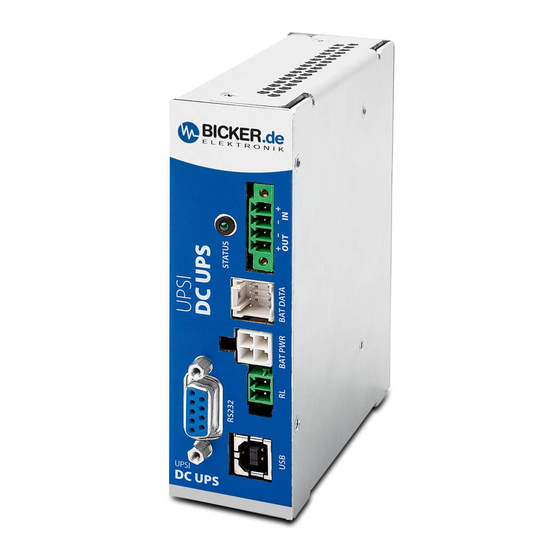
- Page 1 English User Manual UPSI-1208D UPSI SYSTEM DIN RAIL Bicker Elektronik GmbH Ludwig-Auer-Straße 23 | 86609 Donauwörth · Germany...
- Page 2 UPSI-1208D Legend of used symbols Symbol Description Attention! Important hazard warning. Do not dispose of in the domestic waste. Warning of electrical voltage. Revision Directory Date Change 09.08.2021 Initial version Revision 0-1 12.01.2022 Release version Revision 1 Revision 1...
- Page 3 UPSI-1208D Revision 1...
-
Page 4: A Brief Specification Upsi-1208D
UPSI-1208D A Brief specification UPSI-1208D 12 V DC / 8 A 12 V DC UPS (DIN rail version) Intelligent input current detection Regulated output voltage in battery mode Minimum load detection Power fail timer function ... -
Page 5: Table Of Contents
UPSI-1208D Brief specification UPSI-1208D ................4 Introduction and description ................6 B1 Description of the product and its functions ....................6 B2 Intended use .................................7 Safety instructions ....................8 Technical Data ....................... 9 D1 General Technical Data ............................9 D2 Drawing ................................... 17 Name / Address / Support E-Mail / Phone number of the manufacturer .. -
Page 6: B Introduction And Description
B1 Description of the product and its functions The UPSI-1208D (hereinafter also called UPS) is a DC / DC UPS system with numerous digital features and high performance. The UPS can be operated with different energy storage devices (hereinafter also called batte- ry(s)), which are different in technology, capacity and chemistry. -
Page 7: B2 Intended Use
UPSI-1208D B2 Intended use This device is designed to be installed into a suitable enclosure which protects against electrical, water and fire hazards and can then be used indoors and outdoors. It is primary built for being mounted on a DIN Rail and is intended for professional use in applications such as industrial control, communication and measurement technology. -
Page 8: C Safety Instructions
UPSI-1208D C Safety instructions WARNING! Disregarding of following issues can result in electric shock, fire, serious injury or death. 1. Care must be taken to ensure proper and professional wiring. 2. The device pack must not be exposed to fire and temperatures outside the specification. -
Page 9: D Technical Data
UPSI-1208D D Technical Data D1 General Technical Data INPUT DATA – UPSI-1208D Unless otherwise stated, all specifications apply to 25 °C ambient temperature, 12 V DC input voltage and nominal output current (I Input voltage 12 V DC Input voltage range 11.5 V DC…16 V DC... - Page 10 UPSI-1208D OUTPUT DATA – UPSI-1208D (NORMAL MODE) Unless otherwise stated, all specifications apply to 25 °C ambient temperature, 12 V DC input voltage and nominal output current (I Output voltage 12 V DC Output voltage range – 0.6 V DC max. (depending on load) Capacitive load 3000 µF (at start)
- Page 11 UPSI-1208D CONNECTION DATA INPUT / OUTPUT Connection method Screwable plug connector Conductor cross-section solid 0.129 mm² … 1.31 mm² (26 … 16 AWG) Conductor cross-section flexible 0.129 mm² … 1.31 mm² (26 … 16 AWG) Conductor cross-section with ferrule 0.129 mm² … 1.31 mm² (26 … 16 AWG) Stripping length 6 mm …...
- Page 12 UPSI-1208D CONNECTION DATA – RELAY Connection labeling Switch contact (potential free) Relay Status (configurable) Power Fail Alarm Switching voltage 24 V DC / 125 V AC Current carrying capacity 1 A (DC) / 0.5 A (AC) State - signal assignment NO (Normally Open) / NC (Normally Closed) –...
- Page 13 UPSI-1208D DATA INTERFACE – RS232 Interface designation RS232 Numbers of interfaces Connection method DSUB 9-Pin (female) Locking Transmission physics RS232 light (TX / RX) Topology Point-to-point Symbol rate (baud rate) 38400 Type of cable Transmission length ≤10 m Access time <...
- Page 14 UPSI-1208D ENVIRONMENTAL CONDITIONS Ambient temperature (operation) -20… +70 °C Ambient temperature (start up without load) -30 °C Ambient temperature -30…+70 °C (storage / transport) Max. permitted humidity ≤95 % (at +25 °C, no dew) Operating altitude ≤4000 m Climate class...
- Page 15 UPSI-1208D INTERFERENCE IMMUNITY ACCORDING TO EN 61000 (INDUSTRY) Basic standard CE Fulfilled requirements according to EN 61000 (CE) (Interference immunity of industrial environment) Electrostatic discharge EN 61000-4-2 Contact discharge 4 kV Air discharge 8 kV Comment Criterion B Electromagnetic HF field...
- Page 16 UPSI-1208D EMISSION ACCORDING TO EN 55016-2-3 (DOMESTIC) Basic standard CE Fulfilled requirements according to EN 55016-2-3 (CE) (Domestic) Conducted emission from the power port EN 55016-2-3 Frequency range 150 kHz–30 MHz Comment Conform Electric field radiated emission EN 55016-2-3 Frequency range 30 MHz–1 GHz...
-
Page 17: D2 Drawing
100 mm 36 mm 8.5...9 mm E Name / Address / Support E-Mail / Phone number of the manufacturer Bicker Elektronik GmbH · Ludwig-Auer-Straße 23 · 86609 Donauwörth · Germany E-Mail: support@bicker.de · Tel.: +49 (0) 906 70595-0 Revision 1... -
Page 18: F General Data
UPSI-1208D F General Data F1 Assembly and installation advice Installation and operation of this device is only allowed to be executed by a qualified electrician! The application has to be separated from any power during the mounting process. Wires have to be connected safely and must not have contact with sharp edges. Pay attention... - Page 19 UPSI-1208D DIN-Rail mounting and DIN-Rail profile according to EN 60715 Push down Revision 1...
-
Page 20: F3 Description Of Connectors
UPSI-1208D F3 Description of connectors INPUT & OUTPUT (IN & OUT) FUNCTION Vin + Vin – Vout – Vout + RELAY CONNECTION (RL) The function of the relay connection is configurable via software. When closing the relay the resistor value between both contacts is approx. 0 Ω, otherwise they are „open load“. - Page 21 UPSI-1208D BATTERY POWER (BAT PWR) FUNCTION Battery – Battery – Battery + Battery + BATTERY DATA (BAT DATA) FUNCTION Internal temperature sensor to energy storage, connector 1 I²C_0-SCL Internal temperature sensor to energy storage, connector 2 I²C_0-SDA SP0 (battery enable) +5 V (max.
-
Page 22: F4 Dimensioning The Upstream Power Supply
The input has to be supplied from a SELV or PELV power supply. In order to operate the UPSI-1208D with complete functionality, the upstream power supply has to provide at least 12 V / 10 A and use no constant current function. -
Page 23: F5 Connecting Diagram
UPSI-1208D F5 Connecting diagram APPLICATION – – ENERGY STORAGE BAT DATA BAT PWR Relay RS232 (DSUB9) for individual use CONNECTING ORDER 1. BAT PWR 2. BAT DATA 3. APPLICATION (V – ATTENTION! 4. DC SOURCE (V 5. RELAY / USB / RS232 1. -
Page 24: F6 Initial Operation
After that, the charging of the energy storage starts. Only energy storages by Bicker Elektronik may be used. These are appropriately qualified and have the neces- sary protective functions. In addition, the charging methods are set using internal codes and settings. -
Page 25: F7 Overview Connector / Counterpart With Description / Scope Of Delivery
Würth Elektronik 624008213322 SCOPE OF DELIVERY QUANTITY DESCRIPTION 1x device UPSI-1208D - DC UPS connector counterpart Relay connector counterpart F8 Charging time Charging times depend on energy storage, input voltage and the load current. F9 Reverse polarity / Overcurrent / Short circuit... -
Page 26: F10 Backup Time In Battery Mode
If the allowable output current during battery mode exceeds more than 70 %, the converter switches off first, without separating the output immediately. In this case, the voltage at the output of the UPSI-1208D can drop significantly below 12 V. This condition should be avoided by shutting down the system in time. -
Page 27: F12 Status Led
UPSI-1208D F12 Status LED Valid from firmware version 2.1.19 MAIN STATES Always on Status: mains voltage >> Mains voltage is present. 1 Hz flash Status: Battery mode (1 s on, 1 s off) >> Mains voltage is not present. INTERNAL STATES... -
Page 28: F13 Shutdown Diagram
UPSI-1208D F13 Shutdown diagram False Power Fail True Ignition-Timer True Enabled False Shutdown SOC Max. Backup Shutdown-Timer Ignition Pin False Enabled Enabled OS Enabled High True True True True False False Shutdown SOC Max. Backup Shutdown-Timer Ignition Timer Threshold Time Timeout... -
Page 29: F14 Recommendations For A Long Ups Service Life
F17 Disclaimer We, the Bicker Elektronik GmbH, have checked the contents of this document for compliance with the hard- ware and software described. Nevertheless, deviations can not be ruled out, so we assume no liability for the complete agreement. The information in this publication is checked regularly, necessary corrections are inclu- ded in the updated versions. -
Page 30: F18 Preventive Measures And Rules When Operating The Ups System
UPSI-1208D F18 Preventive measures and rules when operating the UPS system The voltage drop of the supply line has to be kept in mind! The maximum charge current can cause huge vol- tage drops if too long supply lines are used. If the voltage drop is too high a shortfall of the threshold values is possible and a not intended Power Fail could be caused. - Page 31 Bicker Elektronik GmbH Ludwig-Auer-Straße 23 86609 Donauwörth · Germany Tel. +49 (0) 906 70595-0 Note: Subject to errors and technical modifications! +49 (0) 906 70595-55 Windows® is a registered trademark of the Microsoft Corp. E-Mail info@bicker.de Status as at: 12.01.2022 – Revision 1...
Need help?
Do you have a question about the UPSI-1208D and is the answer not in the manual?
Questions and answers