
Related Manuals for Bicker Elektronik UPSI-B-2440


Summary of Contents for Bicker Elektronik UPSI-B-2440
- Page 1 USV-Systeme Benutzerhandbuch / User’s Manual UPSI-B-2440 Industrie-PC-Netzteile Netzteile Medizintechnik DC/DC-Wandler USV-Systeme...
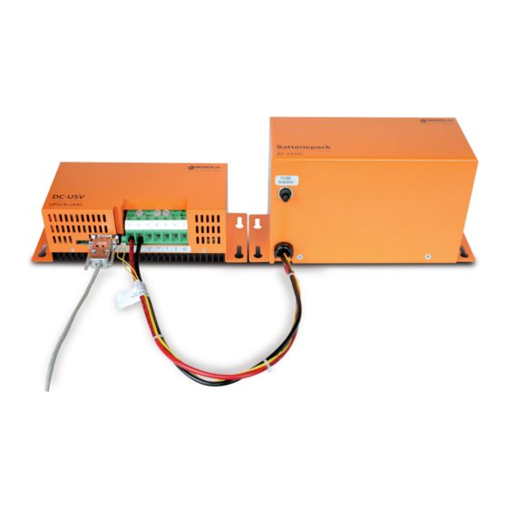
- Page 2 UPSI-B-2440 BP-2450C, optionales Zubehör...
-
Page 3: Table Of Contents
Montage und Inbetriebnahme ......10 TEMP-Anschluss ................. 11 DC-Anschluss ................11 LED-Anschluss ................11 Schnittstelle 9-polig Sub-D ............. 12 RUPS2000 OEM (USV-Softwarepaket) ......... 13 Besonderes Verhalten der UPSI-B-2440 ......14 Ausschalten manuell (ohne USV-Management-Software) Fehlerbehebung ..........15 Bicker Elektronik GmbH Tel. +49 (0)906 70595-0 www.bicker.de... - Page 4 Benutzerhandbuch UPSI-B-2440 Bicker Elektronik GmbH Tel. +49 (0)906 70595-0 www.bicker.de info@bicker.de...
-
Page 5: Allgemeines Und Hinweise
Herzlichen Glückwunsch zu Ihrer neuen UPSI-B-2440! Dieses Handbuch soll Sie mit den Komponenten und Eigenschaften der DC-USV UPSI-B-2440 vertraut machen. Wir haben alle Sorgfalt walten lassen, um in diesem Handbuch vollständige und genaue Informationen über unser Produkt zu liefern. Für möglicherweise vorhandene Fehler kann jedoch keine Haftung übernommen wer-... -
Page 6: Technische Daten
Benutzerhandbuch UPSI-B-2440 2 Technische Daten der DC-USV UPSI-B-2440 T e c h n i s c h e D a t e n Eingangsspannung 24 V DC (20…32 V) Eingangsstrom 42,5 A max. Ausgangsspannung Im Normalbetrieb: ca. 0,4 V unterhalb der Eingangsspannung Im Batteriebetrieb: ca. - Page 7 Benutzerhandbuch UPSI-B-2440 Zeichnung UPSI-B-2440 204,0 mm BAT BAT OUT OUT IN 254,0 mm 25,0 mm 10,0 mm DC-USV UPSI-B-2440 234,0 mm Toleranz ±0,5 mm Präzise Ladungssteuerung durch Mikrocontroller, Ladekennlinie Batterieladestrom Schnell-Ladung Umschaltung auf Erhaltungsladung Trickle Charge Ladespannung Ladespannung Ladeschluss- spannung...
-
Page 8: Funktionsprinzip
Im Netz-Betrieb liefert eine vorgeschaltete Spannungsquelle 24 V DC. Diese Spannung abzüglich 0,4 V DC liegt direkt am Verbraucher (z. B. PC) an. Der angeschlossene Batteriepack wird von der UPSI-B-2440 geladen. Die LED leuchtet grün und die Schnittstelle signalisiert „Power ok“. Etwa alle 10 Minuten wird ein Batterietest durch- geführt. -
Page 9: Led-Anzeige
Die LED leuchtet grün, solange eine Eingangsspannung (>20 V DC) vorhanden ist. LED orange: Die LED leuchtet orange, sobald die DC-USV UPSI-B-2440 in den Batterie-Betrieb schaltet (Eingangsspannung <20 V DC). LED rot/orange blinkend: Die LED blinkt im Batterie-Betrieb rot/orange, wenn die Kapazität des angeschlossenen Batteriepacks abnimmt (Batteriespannung sinkt auf <21 V). -
Page 10: Montage Und Inbetriebnahme
7 Erde: GND Hinweis: Am Eingang (F1) und Ausgang (F2) wird empfohlen, bauseits eine Sicherung vorzuschalten. Achtung Die DC-USV UPSI-B-2440 sowie der Batteriepack BP-2450C dürfen nicht kopfstehend montiert werden. Es ist sicherzustellen, dass im Betrieb eine ausreichende Konvektion möglich ist. -
Page 11: Temp-Anschluss
Benutzerhandbuch UPSI-B-2440 Hinweise Der DC-Eingang (DC-Stecker, PIN 5) muss mit einer 50-A-Sicherung abgesichert werden. Beim Anschluss des Batteriepacks BP-2450C und der Ein- und Ausgänge ist auf die richtige Polarität zu achten! Vor dem Einschalten ist die ordnungsgemäße Verkabelung sicherzustellen. Alle Sicherungen müssen gesteckt sein, insbesondere auch die des Batteriepacks. -
Page 12: Schnittstelle 9-Polig Sub-D
Shutdown Bei Anlegen einer Spannung während des Batterie-Betriebs und nach Ablauf von 2 Minuten Shutdown-Unterdrückung (Punkt 5.6) von +5...24 V DC an PIN6, schaltet die UPSI-B-2440 nach ca. 5 Sekunden ab. Für einen digitalen Ausgang (SPS) kann ein „Pull-UP“- Widerstand berechnet werden. -
Page 13: Rups2000 Oem (Usv-Softwarepaket)
Benutzerhandbuch UPSI-B-2440 5.5 RUPS 2000 OEM (USV-Softwarepaket) Das USV-Softwarepaket unterstützt die folgenden Windows®-Betriebssysteme: 3.1, 98, NT, ME, 2000, 2003, XP und Vista (andere OS auf Anfrage). Die Open Kollektorschnittstelle des DC-USV-Moduls UPSI-B-2410 ist für die Software RUPS 2000 OEM konzipiert. Diesem Softwarepaket liegt ein rotes Schnittstellen-Kabel (M2501) bei. -
Page 14: Besonderes Verhalten Der Upsi-B-2440
Benutzerhandbuch UPSI-B-2440 5.6 Besonderes Verhalten der UPSI-B-2440 Reboot-Funktion Kehrt während eines Netzausfalls und der schon eingeleiteten Shutdown-Phase von Windows® das Netz wieder zurück, so „hängt“ das Betriebssystem mit der Meldung: „Sie können den PC jetzt ausschalten“. Die Reboot- Funktion schaltet das System nach erfolgtem Shutdown aus und nach ca. -
Page 15: Fehlerbehebung
LED blinkt rot/grün Leitungsbruch oder Sicherungsdefekt auf der Batterieseite Kein Batteriepack angeschlossen Die UPSI-B-2440 schaltet in Verbindung mit RUPS 2000 OEM nicht ab. Das Häkchen unter „Settings“, „Shutdown“ und „USV abschalten“ wurde nicht gesetzt. Die Shutdown-Unterdrückungszeit (Punkt 5.5) wurde nicht abgewartet, und somit wurde der Shutdown-Impuls „unterdrückt“. - Page 16 UPSI-B-2440 BP-2450C, optional accessory...
- Page 17 DC connector ................25 LED connector (optional) ............25 Interface 9-pole Sub-D .............. 26 RUPS2000 OEM (UPS Software Package) ......27 Special Features of the UPSI-B-2440........28 Manual Switch-Off (without UPS Management Software) . Troubleshooting ..........29 Bicker Elektronik GmbH Tel.
- Page 18 User’s Manual UPSI-B-2440 Bicker Elektronik GmbH Tel. +49 (0)906 70595-0 www.bicker.de info@bicker.de...
-
Page 19: General Information And Safety Warnings
1 General Information and Safety Warnings Congratulations for choosing the UPSI-B-2440! This manual explains the components and properties of the DC UPS UPSI-B-2440. All information contained in this manual has been revised thoroughly to ensure accuracy and completeness. Yet Bicker Electronic accepts no liability for any omissions or faults. -
Page 20: Technical Data
User’s Manual UPSI-B-2440 2 Technical Data of the DC-UPS UPSI-B-2440 T e c h n i c a l d a t a Input voltage 24 V DC (20…32 V) Input current 42.5 A max. Output voltage Normal mode: app. 0.4 V below input voltage Battery mode: app. - Page 21 User’s Manual UPSI-B-2410 Drawing UPSI-B-2440 204,0 mm BAT BAT OUT OUT IN 254,0 mm 25,0 mm 10,0 mm DC-USV UPSI-B-2440 234,0 mm Tolerance ±0.5 mm Exact charging via microcontroller Charging current Fast charge Float charge Trickle charge Charging voltage Charging voltage...
-
Page 22: Functional Description
User’s Manual UPSI-B-2440 3 Functional Description In case of a mains voltage failure the DC UPS UPSI-B-2440 supplies the connected consumer load with DC voltage from the connected battery pack. Via LED display the status is visualised. Signals can be informed to a connected PC via interface. -
Page 23: Led Display
User’s Manual UPSI-B-2440 4 LED Display (optional) LED green: The LED is green as long as an input voltage (>20 V DC) is present. LED orange: The LED turns to orange as soon as the DC UPS UPSI-B-2410 switches to battery mode (input voltage <20 V DC). -
Page 24: Installation And Commissioning
Note: Installing a fuse on site at both the input (F1) and output (F2) is recommended. Attention Do neither mount the DC UPS UPSI-B-2440 nor the battery pack BP-2450C upside down. Make sure sufficient convection is possible during operation. -
Page 25: Temp Connector
User’s Manual UPSI-B-2440 Notes The DC input (DC connector, PIN 5) must be protected by a 50 A fuse. Observe the correct polarity when connecting the battery pack BP-2450C as well as the inputs and outputs! Before switching on the unit, make sure all connections are correct. -
Page 26: Interface 9-Pole Sub-D
“conductive“. Shutdown When a voltage of +5...24 V DC is supplied at PIN6 during battery mode and after 2 minutes of shutdown suppression (see 5.6), the UPSI-B-2440 switches off after app. 5 seconds. For a digital output (SPS) a “Pull-UP“... -
Page 27: Rups2000 Oem (Ups Software Package)
User’s Manual UPSI-B-2440 5.5 RUPS 2000 OEM (UPS Software Package) The UPS software package supports the following operating systems of Windows®: 3.1, 98, NT, ME, 2000, 2003, XP and Vista (other OS upon request). The open collector interface of the DC UPS module UPSI-B-2410 has been designed for the software RUPS 2000 OEM. -
Page 28: Special Features Of The Upsi-B-2440
User’s Manual UPSI-B-2440 5.6 Special Features of the UPSI-B-2440 Reboot Function If DC IN fails and main power returns during shutdown mode of Windows®, the ope- rating system will ‘lock’ with the message “Your PC is now safe”. The reboot function switches the system off after shutdown and restarts after about 5 seconds. -
Page 29: Troubleshooting
LED flashes red/green Connection interrupted or defect fuse on battery side Battery pack not connected The UPSI-B-2440 does not switch off in connection with RUPS 2000 OEM. The checkmark under “Settings“, “Shutdown“ and “Switch off UPS“ (USV abschalten) was not set. - Page 30 User’s Manual UPSI-B-2440 Notizen / Notes Bicker Elektronik GmbH Tel. +49 (0)906 70595-0 www.bicker.de info@bicker.de...
- Page 31 User’s Manual UPSI-B-2440 Notizen / Notes Bicker Elektronik GmbH Tel. +49 (0)906 70595-0 www.bicker.de info@bicker.de...
- Page 32 Industrial PC PSUs Power supplies Medical applications DC/DC converters UPS systems Bicker Elektronik GmbH Ludwig-Auer-Straße 23 86609 Donauwörth · Germany Tel. +49 (0)906 70595-0 Fax +49 (0)906 70595-55 E-Mail: info@bicker.de Internet: www.bicker.de...
Need help?
Do you have a question about the UPSI-B-2440 and is the answer not in the manual?
Questions and answers