
Related Manuals for Bicker Elektronik UPSI-2406DP


Summary of Contents for Bicker Elektronik UPSI-2406DP
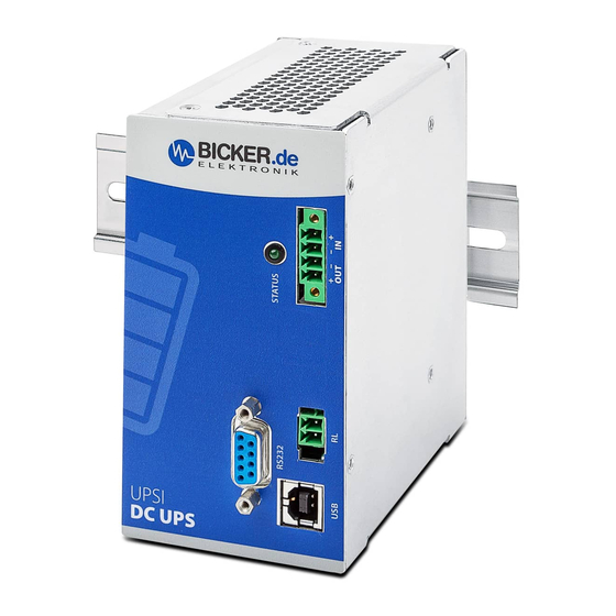
- Page 1 English User Manual UPSI-2406DPx UPS SYSTEM DIN-RAIL Bicker Elektronik GmbH Ludwig-Auer-Straße 23 | 86609 Donauwörth · Germany...
- Page 2 UPSI-2406DPx Legend of used symbols Symbol Description Attention! Important hazard warning. This user manual has to be read before installation of the device and before any work on this device. Do not dispose of in the domestic waste. Warning of electrical voltage. Revision Directory Date Change...
- Page 3 UPSI-2406DPx Revision 1-4...
-
Page 4: A Brief Specification Upsi-2406Dp1 / Upsi-2406Dp2 / Upsi-2406Dp3
UPSI-2406DPx A Brief specification UPSI-2406DP1 / -DP2 / -DP3 24 V DC / 4 A 24 V DC UPS (DIN rail version) Integrated Li-Ion batteries (DP1) OR maintenance-free Supercaps (DP2) OR LiFePO4 battery (DP3) Cycle Life ≥500 (DP1) | >500 000 (DP2) | ... - Page 5 UPSI-2406DPx Backup time* UPSI-2406DP1 Nominal backup time vs. P Output Power [W] Backup time* UPSI-2406DP2 Nominal backup time vs. P Output Power [W] *Backup time depends on battery capacitance, load and temperature. At very high or low temperatures a reduction of backup time occurs. Unless otherwise specified, the values apply to measurements at +25 °C Revision 1-4...
- Page 6 UPSI-2406DPx Backup time* UPSI-2406DP3 Nominal backup time vs. P BP-LFP-1325(D): Backup (me nominal vs. Pout 200 180 160 140 120 100 100 110 120 130 140 Pout [W] Output Power [W] *Backup time depends on battery capacitance, load and temperature. At very high or low temperatures a reduction of backup time occurs. Unless otherwise specified, the values apply to measurements at +25 °C Revision 1-4...
-
Page 7: Table Of Contents
UPSI-2406DPx Brief specification UPSI-2406DP1 / UPSI-2406DP2 / UPSI-2406DP3 ....4 Intended use ......................8 B1 Description of the product and its functions UPSI-2406DP1 / -DP2 / -DP3......8 B2 Read carefully before initial operation! ......................8 B3 Intended use – Description ...........................8 B4 Safety instructions ...............................9 Technical Data ..................... -
Page 8: B Intended Use
UPSI-2406DPx B Intended use Congratulations for choosing a quality product! This manual shall help the user to get familiar with the product and its components and features. It shall provide information as accurately and completely as possible. However, for possible errors no liability can be assumed. -
Page 9: B4 Safety Instructions
UPSI-2406DPx B4 Safety instructions WARNING! Disregarding of following issues can result in electric shock, fire, serious injury or death. 1. Care must be taken to ensure proper and professional wiring. 2. The device pack must not be exposed to fire and temperatures outside the specification. 3. -
Page 10: C Technical Data
UPSI-2406DPx C Technical Data C1 General Technical Data INPUT DATA – UPSI-2406DP1 / UPSI-2406DP2 / UPSI-2406DP3 Unless otherwise stated, all specifications apply to 25° C ambient temperature, 24 V DC input voltage and nominal output current (I Input voltage 24 V DC Input voltage range 22.5 V DC…30 V DC Electric strength max. - Page 11 UPSI-2406DPx OUTPUT DATA – UPSI-2406DP1 / UPSI-2406DP2 / UPSI-2406DP3 (NORMAL MODE) Unless otherwise stated, all specifications apply to 25° C ambient temperature, 24 V DC input voltage and nominal output current (I Output voltage 24 V DC Output voltage range –...
- Page 12 UPSI-2406DPx CONNECTION DATA INPUT / OUTPUT Connection method Screw connection Conductor cross-section solid 0.129 mm² … 1.31 mm² (26 … 16 AWG) Conductor cross-section flexible 0.129 mm² … 1.31 mm² (26 … 16 AWG) Conductor cross-section with ferrule 0.129 mm² … 1.31 mm² (26 … 16 AWG) Stripping length 6 mm …...
- Page 13 UPSI-2406DPx ENERGY STORAGE UPSI-2406DP3 (BP-LFP-1325) Charging characteristic CC / CV / CP Nominal voltage U 12.8 V DC End-of-charge voltage 13.8 V DC Charging current 4.5 A max. Discharge current 15 A max. Low-voltage protection 8.8 V Battery technology LiFePO4 Nominal capacity 2.5 Ah / 33 Wh Charging time (I_charge_max)
- Page 14 UPSI-2406DPx CONNECTION DATA – RELAY Connection labeling Switch contact (floating) Relay Status (configurable) Power Fail Alarm State condition (configurable) Input voltage <22.5 V DC Switching voltage 24 V DC / 125 V AC Current carrying capacity 1 A (DC) / 0.5 A (AC) State - signal assignment NO (Normaly Open) / NC (Normaly Closed) –...
- Page 15 UPSI-2406DPx DATA INTERFACE – RS232 Interface designation RS232 Numbers of interfaces Connection method DSUB 9-Pin (female) Locking Transmission physics RS232 light (TX / RX) Topology Point-to-point Symbol rate (baud rate) 38400 Type of cable Transmission length ≤10 m Access time <...
- Page 16 UPSI-2406DPx ENVIRONMENTAL CONDITIONS – UPSI-2406DP1 / UPSI-2406DP2 / UPSI-2406DP3 Ambient temperature (operation) DP1: 0…+50° C / DP2: -20… +65° C / DP3: -20… +55° C Ambient temperature (start up without load) DP2: -30° C, DP3: -20° C Ambient temperature DP1: -20…+50° C / DP2: -30…+65° C / DP3: -30…+55° C (storage / transport) Max.
- Page 17 UPSI-2406DPx INTERFERENCE IMMUNITY ACCORDING TO 61000-6-2 (INDUSTRY SECTOR) Basic standard CE Normative minimum requirements EN 61000-6-2 (CE) (Interference immunity of industrial environment) Electrostatic discharge EN 61000-4-2 Housing contact discharge 4 kV (test level 2) Housing air discharge 8 kV (test level 3) Comment Criterion A Electromagnetic HF field...
-
Page 18: C2 Drawing
C2 Drawing UPSI-2406DP1 / UPSI-2406DP2 / UPSI-2406DP3 100mm Tolerance ±0.5 mm 63mm D Name / Address / Support E-Mail / Phone number of the manufacturer Bicker Elektronik GmbH · Ludwig-Auer-Straße 23 · 86609 Donauwörth · Germany E-Mail: support@bicker.de · Tel.: +49 (0) 906 70595-0 Revision 1-4... -
Page 19: E General Data
UPSI-2406DPx E General Data E1 Assembly and installation advice Installation and operation of this device is only allowed to be executed from qualified personnel! The application must be separated from any power during the mounting process. Wires have to be connected safely and must not have contact with sharp edges. - Page 20 UPSI-2406DPx DIN-Rail mounting and DIN-Rail profile according to EN 60715 Press down Revision 1-4...
-
Page 21: E3 Description Of Connectors
UPSI-2406DPx E3 Description of connectors INPUT & OUTPUT FUNCTION Vin + Vin – Vout – Vout + RELAY CONNECTION (RL) Normally open contact (NO): When input power is interrupted, the contact is closed (= 0 Ω ). FUNCTION Relay contact 1 Relay contact 2 RS-232 FUNCTION... -
Page 22: E4 Dimensioning The Upstream Power Supply
UPSI-2406DPx E4 Dimensioning the upstream power supply Ensure that the upstream power supply is correctly dimensioned to guarantee the charging process of the batteries and the correct functioning of the application. The input must be supplied from a SELV or PELV power supply. -
Page 23: E5 Initial Operation
UPSI-2406DPx E5 Initial operation Ensure that the UPS is correctly installed. Via connection to upstream power supply: When an input voltage higher than 22.5 V is connected to the input terminals, the energy storage medium gets queried and transmits its data. Only then the charger gets enabled and the charging of the battery pack starts. -
Page 24: E6 Connecting Diagram
UPSI-2406DPx E6 Connection – – RELAY RS232 for individual use D Sub 9 CONNECTING ORDER 1. APPLICATION (V 2. DC SOURCE (V 3. RELAY / USB / RS232 Dismantling order reverse to connection! – ATTENTION! 1. Note polarity! 2. AWG18 wire should be used (1 mm Revision 1-4... -
Page 25: E7 Overview Connector / Counterpart With Part No. / Scope Of Delivery
UPSI-2406DPx E7 Overview connector / counterpart with description / Scope of delivery CONNECTOR PART NO. COUNTERPART NO. Würth Elektronik 691325310004 Würth Elektronik 691364300004 Würth Elektronik 691305140002 Würth Elektronik 691304130002 Würth Elektronik 61400416121 USB type B connector RS232 D-Sub9 Female D-Sub 9 Male SCOPE OF DELIVERY QUANTITY DESCRIPTION... -
Page 26: E11 Behavior In Case Of Exceeding Maximum Backup Time
UPSI-2406DPx E11 Behaviour in case of exceeding maximum backup time When the given buffering times are exceeded, the output is separated on the basis of the discharge voltage of the corresponding storage medium (total discharge protection). For supercapacitors, which are not sensitive to a deep discharge, a threshold has been definded which is limi- ted by the current. -
Page 27: E13 Software
E17 Disclaimer We, the Bicker Elektronik GmbH, have checked the contents of this document for compliance with the hard- ware and software described. Nevertheless, deviations can not be ruled out, so we assume no liability for the complete agreement. The information in this publication is checked regularly, necessary corrections are inclu- ded in the updated versions. -
Page 28: E18 Preventive Measures And Rules When Operating The Ups System
UPSI-2406DPx E18 Preventive measures and rules when operating the UPS system The voltage drop of the supply line has to be kept in mind! The maximum charge current can cause huge vol- tage drops if too long supply lines are used. If the voltage drop is too high a shortfall of the threshold values is possible and a not intended Power Fail could be caused. - Page 29 Bicker Elektronik GmbH Ludwig-Auer-Straße 23 86609 Donauwörth · Germany Tel. +49 (0) 906 70595-0 Note: Subject to errors and technical modifications! +49 (0) 906 70595-55 Windows® is a registered trademark of the Microsoft Corp. E-Mail info@bicker.de Status as at: 25.11.2020 – Revision 1-4...
Need help?
Do you have a question about the UPSI-2406DP and is the answer not in the manual?
Questions and answers