
Related Manuals for Bicker Elektronik UPSI-B-2410


Summary of Contents for Bicker Elektronik UPSI-B-2410
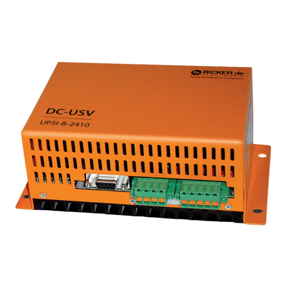
- Page 1 USV-Systeme Benutzerhandbuch / User’s Manual UPSI-B-2410 Industrie-PC-Netzteile Netzteile Medizintechnik DC/DC-Wandler USV-Systeme Systemkomponenten...
-
Page 2: Table Of Contents
UPSI-B-2410 LED-Anzeige .............9 Montage und Inbetriebnahme ......10 DC-Stecker1 .................. 11 DC-Stecker2 .................. 11 Schnittstelle 9-polig Sub-D ............. 12 RUPS2000 OEM (USV-Softwarepaket) ......... 13 Besonderes Verhalten der UPSI-B-2410 ......14 Ausschalten manuell (ohne USV-Management-Software) Fehlerbehebung ..........15 BP-2425C, optionales Zubehör... -
Page 3: Allgemeines Und Hinweise
1 Allgemeines und Hinweise Herzlichen Glückwunsch zu Ihrer neuen UPSI-B-2410! Dieses Handbuch soll Sie mit den Komponenten und Eigenschaften der DC-USV UPSI-B-2410 vertraut machen. Wir haben alle Sorgfalt walten lassen, um in diesem Handbuch vollständige und genaue Informationen über unser Produkt zu liefern. Für möglicherweise vorhandene Fehler kann jedoch keine Haftung übernommen wer- den. Hinweise auf vorhandene Fehler, Verbesserungsvorschläge und Kritik nehmen wir dankbar entgegen. -
Page 4: Technische Daten
Benutzerhandbuch UPSI-B-2410 Benutzerhandbuch UPSI-B-2410 2 Technische Daten der DC-USV UPSI-B-2410 Zeichnung UPSI-B-2410 T e c h n i s c h e D a t e n Eingangsspannung 24 V DC (20…36 V) 152,00 mm Eingangsstrom 12,5 A max. Ausgangsspannung Im Normalbetrieb: ca. 0,4 V unterhalb der Eingangsspan. Im Batteriebetrieb: ca. 30,9…19 V DC Ausgangsstrom 10 A max. Batterieladestrom 2 A max. (interner Batterielader) 7,00 mm Ladeschluss-Spannung 26,4…31,2 V, temperaturabhängig... -
Page 5: Funktionsprinzip
3.1 Netz-Betrieb Im Netz-Betrieb liefert eine vorgeschaltete Spannungsquelle 24 V DC. Diese Spannung abzüglich 0,4 V DC liegt direkt am Verbraucher (z. B. PC) an. Der angeschlossene Batteriepack wird von der UPSI-B-2410 geladen. Die LED leuchtet grün und die Schnittstelle signalisiert „Power ok“. Etwa alle 10 Minuten wird ein Batterietest durch- geführt. Bei defektem Akku oder z. B. nicht angeschlossenem Batteriepack blinkt die LED rot/grün. 1 2 3 4 1 2 3 4 5 3.2 ... -
Page 6: Montage Und Inbetriebnahme
2 Eingang (–) Sicherungen müssen gesteckt sein, insbesondere auch die des Batteriepacks. 3 Batterie (+) 3 Ausgang (+) 4 Batterie (-) 4 Eingang (+) 5 Erde 5.1 DC-Stecker 1: Anschluss Batteriepack An diesen Steckverbinder wird der Batteriepack BP-2425C angeschlossen. Nur mit diesem Batteriepack kann die DC-USV UPSI-B-2410 im Temperaturbereich von -30…+70 °C eingesetzt werden. Temp Temp PIN – 1 Temperatur-Fühler Batterie 2 Temperatur-Fühler Batterie 3 Batterie (+) Hinweis: Am Eingang (F1) und Ausgang (F2) wird empfohlen, bauseits eine Sicherung vorzuschalten. -
Page 7: Schnittstelle 9-Polig Sub-D
PIN 2003, XP, Vista, 7 und 8 (andere OS auf Anfrage). Die Open Kollektorschnittstelle 1 n.c. 6 Shutdown Eingang des DC-USV-Moduls UPSI-B-2410 ist für die Software RUPS 2000 OEM konzipiert. 2 Power Fail (Kollektor) Ausgang 7 Bezug Shutdown Diesem Softwarepaket liegt ein rotes Schnittstellen-Kabel (M2501) bei. Damit kann 3 n.c. -
Page 8: Besonderes Verhalten Der Upsi-B-2410
Batterie versorgt. Soll diese Batteriespannung auch Batterie wird nicht voll geladen abgeschalten werden, muss die Sicherung des Batteriepacks nach Abschalten des Temperaturfühler kurzgeschlossen oder unterbrochen Verbrauchers herausgenommen werden. Batteriepack defekt Keine Funktion Eingangsspannung verpolt? > > Eingangssicherung erneuern Eingangssicherung defekt? >> Eingangssicherung erneuern Leitungsquerschnitt zu „klein“? > > Empfohlener Leitungsquerschnitt 2,5 mm Der Überspannungsschutz am Eingang (ab 40 V DC) hat angesprochen. Die interne Supressor-Diode schließt kurz und die Eingangssicherung löst aus. Dabei geht das UPSI-B-2410 in Batterie-Betrieb. > > Eingangssicherung erneuern || || || || || || Bicker Elektronik GmbH Tel. +49 (0)906 70595-0 www.bicker.de info@bicker.de Bicker Elektronik GmbH Tel. +49 (0)906 70595-0... - Page 9 User’s Manual UPSI-B-2410 1 General Information and Safety Warnings .... 5 1.1 Contents of Delivery .............. 5 1.2 Optional Accessories .............. 5 2 Technical Data ............ 6 3 Functional Description ........... 8 3.1 Mains Mode .................. 8 3.2 Battery Mode .................. 8 UPSI-B-2410 4 LED Display ...............9 5 Installation and Commissioning ...... 10 ...
-
Page 10: General Information And Safety Warnings
User’s Manual UPSI-B-2410 User’s Manual UPSI-B-2410 1 General Information and Safety Warnings Congratulations for choosing the UPSI-B-2410! This manual explains the components and properties of the DC UPS UPSI-B-2410. All information contained in this manual has been revised thoroughly to ensure accuracy and completeness. Yet Bicker Electronic accepts no liability for any omissions or faults. We will appreciate any notifications regarding faults, suggestions for improvements and criticism. Safety Warnings Installation and connection must only be carried out by qualified personnel. The relevant rules of electrical engineering must be observed! A 15 A fuse must be installed at input line! All connector cables must be dimensioned for the max. input current of the UPSI-B-2410 (12.5 A) and an according additional protection must be provided. The recommended cross section for the connector cables is 2.5 mm A polarity reversal can damage the UPS as well as the connected load. Charging the battery pack BP-2425C every six months with the DC UPS UPSI-B-2410 is recommended during storage or when the battery pack is not in use. 1.1 Contents of Delivery DC UPS UPSI-B-2410 Pin-and-socket connector, Phoenix contact, 4- and 5-pole Manual 1.2 Optional Accessories Battery pack BP-2425C incl. pin-and-socket connector, Phoenix contact, 4-pole RUPS 2000 OEM, UPS Management Software Interface cable 9-pole SUB-D... -
Page 11: Technical Data
User’s Manual UPSI-B-2410 User’s Manual UPSI-B-2410 2 Technical Data of the DC-UPS UPSI-B-2410 Drawing UPSI-B-2410 T e c h n i c a l d a t a Input voltage 24 V DC (20…36 V) 152,00 mm Input current 12.5 A max. Output voltage Normal mode: app. 0.4 V below input voltage Battery mode: app. 30.9…19 V DC Output current 10 A max. -
Page 12: Functional Description
User’s Manual UPSI-B-2410 User’s Manual UPSI-B-2410 3 Functional Description 4 LED Display LED green: In case of a mains voltage failure the DC UPS UPSI-B-2410 supplies the connected consumer load with DC voltage from the connected battery pack. Via LED display the The LED is green as long as an input voltage (>20 V DC) is present. status is visualised. Signals can be informed to a connected PC via interface. LED orange: The LED turns to orange as soon as the DC UPS UPSI-B-2410 switches Source: e. g. AC/DC power supply to battery mode (input voltage <20 V DC). Consumer DC UPS 15 A UPSI-B-2410 load (PC) LED red/orange-flashing: ... -
Page 13: Installation And Commissioning
User’s Manual UPSI-B-2410 User’s Manual UPSI-B-2410 5 Installation and Commissioning Notes The DC input (DC connector 2, PIN 4) must be protected by a 15 A fuse. Connections Observe the correct polarity when connecting the battery pack BP-2425C as well as the inputs and outputs! Before switching on the unit, make sure all connections are correct. DC connector 1 DC connector 2 1 Temp. sensor batt. 1 Output (–) All fuses, especially that of the battery pack, must be engaged. 2 Temp. sensor batt. 2 Input (–) 3 Battery (+) 3 Output (+) -
Page 14: Interface 9-Pole Sub-D
8 n.c. package to connect the UPSI-B-2410 with a free COM-Port of a connected PC. 4 Reference Power Fail, Battery Low (emitter) 9 n.c. 5 Battery Low (collector) output Important basic settings Power Fail In mains mode, the collector-emitter-line of the optocoupler is “nonconducting“. In battery mode (input voltage <20 V DC), the collector-emitter-line of the optocoupler is “conductive“. Battery Low In mains mode, the collector-emitter-line of the optocoupler is “nonconducting“. In battery mode and with low battery voltage (<21 V DC) the collector-emitter-line of the optocoupler is “conductive“. Shutdown When a voltage of +5...24 V DC is supplied at PIN6 during battery mode and after 2 minutes of shutdown suppression (see 5.5), the UPSI-B-2410 switches off after app. 5 seconds. For a digital output (SPS) a “Pull-UP“ resistance can be determined. Data of optocoupler: Power Fail UPSI-B-2410 Uce 24 V DC PIN2 General > > COM Port at PC Interface Ice 0.1 Amax E-Mail >... -
Page 15: Special Features Of The Upsi-B-2410
User’s Manual UPSI-B-2410 User’s Manual UPSI-B-2410 5.5 Special Features of the UPSI-B-2410 7 Troubleshooting Reboot Function No battery mode If DC IN fails and main power returns during shutdown mode of Windows®, the ope- Connection interrupted or defect fuse on battery side rating system will ‘lock’ with the message “Your PC is now safe”. The reboot function Battery pack not connected restarts the system after about 5 seconds. Battery pack has not enough capacitance or is discharged No intervention of the user is required. Polarity reversal of battery pack or supply voltage > > replace input fuse LED flashes red/green Shutdown Suppression Connection interrupted or defect fuse on battery side The shutdown signal is suppressed for about 2 minutes while the system is starting Battery pack not connected up, since a possible interface check of Windows® with a simultaneous power failure would switch the module off. This suppression is only active when the module is The UPSI-B-2410 does not switch off in connection with RUPS 2000 OEM. - Page 16 User’s Manual UPSI-B-2410 User’s Manual UPSI-B-2410 Notizen / Notes Notizen / Notes...
-
Page 17: System Components
Industrial PC PSUs Power supplies Medical applications DC/DC converters UPS systems System components Bicker Elektronik GmbH Ludwig-Auer-Straße 23 86609 Donauwörth · Germany Tel. +49 (0)906 70595-0 Irrtümer und technische Änderungen vorbehalten. Fax +49 (0)906 70595-55 Windows® ist ein eingetragenes Warenzeichen der Firma Microsoft Corp. E-Mail: info@bicker.de Subject to errors and technical modifications. Windows®...
Need help?
Do you have a question about the UPSI-B-2410 and is the answer not in the manual?
Questions and answers