
Related Manuals for SISTEM AIR Industrial Clean


Summary of Contents for SISTEM AIR Industrial Clean
- Page 1 w w w . s i s t e m a i r . c o m MANUALE TECNICO Technical manual Manuel technique Technisches Handbuch Manual técnico...
-
Page 3: Table Of Contents
MANUALE ISTRUZIONI • Tipologia: aspirapolvere centralizzato professionale Linea • Modello: Industrial Clean Industrial Clean • Revisione 1.0.0 INDICE INFORMAZIONI GENERALI UTILIZZO DEL MANUALE DESCRIZIONE DELLA CENTRALE ASPIRANTE 2.1 Particolarità distintive di prodotto CARATTERISTICHE TECNICHE CARATTERISTICHE COSTRUTTIVE CARATTERISTICHE DI SICUREZZA 5.1 Grado di protezione IP 5.2 Grado di isolamento elettrico... - Page 4 MANUALE ISTRUZIONI • Tipologia: aspirapolvere centralizzato professionale Linea • Modello: Industrial Clean Industrial Clean • Revisione 1.0.0 INDICE 10.2.4 Schema elettrico collegamento motori elettronici 11 USO DELLA CENTRALE ASPIRANTE 11.1 Accensione della centrale aspirante 11.2 Utilizzo della centrale aspirante 11.3 Programmazione ed utilizzo del computer di gestione della centrale 11.3.1 Videata principale...
- Page 5 Per l’ottenimento dei migliori risultati, si raccomanda l’uso dei materiali di consumo originali SISTEM AIR. Il marchio di fabbrica SISTEM AIR citato nel presente manuale è un marchio registrato ed appartiene al proprietario TECNOPLUS S.r.l.
-
Page 6: Informazioni Generali
PVC o acciaio zincato sottotraccia, a parete o nel controsoffi tto, che si dirama nei vari locali e alla cui estremità vengono posizionate le prese di aspirazione. La centrale aspirante SISTEM AIR, posizionata in un locale di servizio, box auto o altro disimpegno, viene collegata alla rete tubiera di aspirazione. -
Page 7: Particolarità Distintive Di Prodotto
Sistem Air ha inoltre realizzato un software che, installato su un personal computer, permette di visua- lizzare le indicazioni circa il funzionamento del sistema mediante un collegamento con cavo di rete ethernet e relativa scheda di interfaccia (a richiesta). -
Page 8: Caratteristiche Tecniche
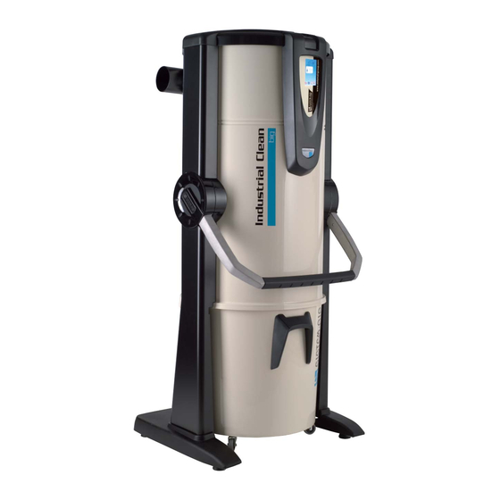
Manuale istruzioni Industrial Clean 3- CARATTERISTICHE TECNICHE G (consigliata) Modello Industrial Clean Trasduttore di pressione Coperchio Valvola rompivuoto Scheda di controllo Computer di Raccordo collegamento bordo Industrial Motor Protezione fi ltro Filtro Raccordo impianto di aspirazione Interruttore generale Maniglia sgancio... - Page 9 Industrial Clean Industrial Industrial Clean Small Clean Big Modello Articolo 3400.0 3400.1 Computer gestione motore Valvola rompivuoto di sicurezza Grado di protezione Alimentazione V ac 220/240 220/240 Frequenza 50/60 50/60 Portata massima aria (motore) 1200 Superfi cie fi ltrante 24000 43400 Capacità...
-
Page 10: Caratteristiche Costruttive
Manuale istruzioni Industrial Clean 4 - CARATTERISTICHE COSTRUTTIVE I separatori polveri ad uso industriale Industrial Clean Small e Industrial Clean Big si prestano ad in- numerevoli soluzioni d’impiego, grazie alla loro versatilità ed abbinabilità con gli altri componenti di un sistema di aspirazione centralizzato di tipo industriale. -
Page 11: Caratteristiche Di Sicurezza
5 - CARATTERISTICHE DI SICUREZZA Si raccomanda di leggere attentamente tutte le indicazioni relative all’installazione, uso e manu- tenzione contenute in questo manuale. Inoltre occorre sempre seguire le seguenti AVVERTENZE: • Non utilizzare la macchina per usi impropri. • Non lasciare che i bambini si avvicinino alla centrale aspirante durante l’uso ne che giochino con essa o con le prese di aspirazione. -
Page 12: Grado Di Protezione Ip
Bedienungsanleitung Industrial Clean HINWEIS: Die Firma TECNOPLUS S.R.L. lehnt jedwede Verantwortung oder Garantieübernahme ab, sollte der Käufer oder eine in seinem Auftrag handelnde Drittperson wenn auch noch so geringe Ände- rungen oder Umstellungen am erworbenen Gerät durchführen. Qualitativ und anwendungsbezogen kann das Gerät, so wie es vom Hersteller entwickelt und gebaut wurde, die Anforderungen des Marktes für Zentralsauganlagen für den Hausgebrauch aufs Beste erfül-... -
Page 13: Sicurezze Relative Ai Ripari Mobili Di Chiusura
5.5 Abnehmbare Schutzabdeckungen Es sind keine abnehmbaren Schutzabdeckungen vorhanden, jede Abdeckung ist fest mittels spezieller Schrauben angebracht. TECNOPLUS s.r.l. weist darauf hin, dass es streng verboten ist, die bei der Geräteentwicklung und -montage verwendeten Schrauben durch solche mit anderen technischen Merkmalen zu ersetzen. Sollte der Kunde irgendwelche Änderungen vornehmen, annulliert TECNOPLUS s.r.l. -
Page 14: Uso Previsto Della Macchina
I separatori di polveri Industrial Clean Small e Big devono essere utilizzati in abbinamento a uno o più motori soffi anti con impianti confi gurati per portate d’aria fi no a 700 m /h per la versione Small, e fi... -
Page 15: Corredo E Accessori
La confezione di vendita della centrale, inoltre, comprende anche il corredo di accessori, composto dai seguenti particolari: N°1 Separatore di polveri Industrial Clean N°2 manicotti in gomma per il collegamento alla rete tubiera di aspirazione N°4 fascette metalliche per il fi ssaggio dei manicotti N°1 manuale d’installazione, uso e manutenzione... -
Page 16: Installazione
DA PERSONALE QUALIFICATO 9.1 INSTALLAZIONE CONSIGLIATA Il Separatore di polvere Industrial Clean in abbinamento a uno o più motori soffi anti è dotato di col- legamento alla tubazione di sfi ato dell’aria, condizione necessaria per poter espellere all’esterno le micropolveri che la cartuccia fi ltro non può trattenere. Deve essere installata in locali tecnici o in locali di servizio (come box, cantine o altro), protetti da intemperie, umidità... -
Page 17: Trasporto E Disimballo
9.2 Trasporto e disimballo Trasportare la centrale ancora imballata, in prossimità del luogo di installazione seguendo le indicazioni riportate sull’imballo ed utilizzando un transpallet o un carrello elevatore. Togliere il cartone di protezione. 15/02/12 Rev:1.0.0 (LINGUA ORIGINALE) - Page 18 Manuale istruzioni Industrial Clean Togliere le staffe che fi ssano la centrale al bancale. Togliere la centrale dal bancale. Se non si dispone di idonei mezzi con forche, è possibile togliere manual- mente la centrale dal bancale (vedi fi gura).
- Page 19 Estrarre tutti gli accessori presenti e smaltire l’imballo in conformità delle leggi vigenti in materia. Rimozione del maniglione. 15/02/12 Rev:1.0.0 (LINGUA ORIGINALE)
-
Page 20: Posizionamento Della Macchina
Manuale istruzioni Industrial Clean 9.3 Posizionamento della macchina Al fi ne di consentire un corretto uso della macchina e un’agevole manutenzione, si consiglia di mantene- re attorno alla stessa gli spazi liberi minimi di 60 cm liberi sui tre lati (escluso il lato di fi ssaggio al muro). - Page 21 Smontare l’imbocco di collegamen- to del gruppo motore soffi ante “C” e la lamiera di chiusura “D” svitan- do le relative viti di fi ssaggio. Rimontare, scambiandone di posto, l’imbocco del tubo di scarico “C” e la lamiera di chiusura “D”...
-
Page 22: Fissaggio Della Centrale
10 MESSA IN SERVIZIO DELLA MACCHINA 10.1 Postazione di comando Il Separatore di polvere Industrial Clean ha una postazione di comando dalla quale si può confi gurare il funzionamento dell’apparecchio, tramite un semplice display interfaccia operatore e 6 tasti funzione. -
Page 23: Collegamento Elettrico
• Collegare il cavo di uscita segnale di attenzione di attivazione (LINEA MICRO 2) al motore elettrico. Nel caso in cui il numero dei motori elettrici sia più di uno, collegare il cavo al quadro elettrico “sele- zione chiamata” Sistem Air. • Verifi care che l’impianto elettrico sia realizzato secondo le norme tecniche elettriche in vigore. -
Page 24: Collegamento Rete Tubiera/Elettrico Motori Elettrici (Industrial Motor Art. 3500.1M, 3500.3M, 3500.5M)
Manuale istruzioni Industrial Clean 10.2.1 Collegamento rete tubiera/elettrico motori elettrici (Industrial Motor art. 3500.1M, 3500.3M, 3500.5M) Figura (A) collegamento separatore polveri con un motore elettrico. Morsettiera collegamenti elettrici R S T 1112 Figura (B) collegamento separatore polveri con due o più motori elettrici. -
Page 25: Schema Elettrico Collegamento Motori Elettrici
10.2.2 Schema elettrico collegamento motori elettrici 1) Schema di collegamento n° 1 separatore polveri con n° 1 motore elettrico. 15/02/12 Rev:1.0.0 (LINGUA ORIGINALE) - Page 26 Manuale istruzioni Industrial Clean 2) Schema di collegamento n° 1 separatore polveri con n° 2 motori elettrici. (LINGUA ORIGINALE) 15/02/12 Rev:1.0.0...
- Page 27 3) Schema di collegamento n° 1 separatore polveri con n° 3 motori elettrici. 15/02/12 Rev:1.0.0 (LINGUA ORIGINALE)
- Page 28 Manuale istruzioni Industrial Clean 4) Schema di collegamento n° 1 separatore polveri con n° 8 motori elettrici. (LINGUA ORIGINALE) 15/02/12 Rev:1.0.0...
- Page 29 5) Schema di collegamento n° 2 separatore polveri con n° 8 motori elettrici. 15/02/12 Rev:1.0.0 (LINGUA ORIGINALE)
-
Page 30: Collegamento Rete Tubiera/Elettrico Motori Elettronici (Industrial Motor Matic Art. 3500.2M, 3500.4M, 3500.6M, 3500.7M)
Manuale istruzioni Industrial Clean 10.2.3 Collegamento rete tubiera/elettrico motori elettronici (Industrial Motor Matic art. 3500.2M, 3500.4M, 3500.6M, 3500.7M) Figura (A) collegamento separatore polveri con un motore elettronico. Morsettiera collegamenti elettrici R S T 1 23 Figura (B) collegamento separatore polveri con due o più motori elettronici. -
Page 31: Schema Elettrico Collegamento Motori Elettronici
10.2.4 Schema elettrico collegamento motori elettronici 1) Schema di collegamento n° 1 separatore polveri con n° 1 motore elettronico. 15/02/12 Rev:1.0.0 (LINGUA ORIGINALE) - Page 32 Manuale istruzioni Industrial Clean 2) Schema di collegamento n° 1 separatore polveri con n° 2 motori elettronici. (LINGUA ORIGINALE) 15/02/12 Rev:1.0.0...
- Page 33 3) Schema di collegamento n° 1 separatore polveri con n° 3 motori elettronici. 15/02/12 Rev:1.0.0 (LINGUA ORIGINALE)
- Page 34 Manuale istruzioni Industrial Clean 4) Schema di collegamento n° 1 separatore polveri con n° 4 motori elettronici. (LINGUA ORIGINALE) 15/02/12 Rev:1.0.0...
- Page 35 5) Schema di collegamento n° 1 separatore polveri con n° 8 motori elettronici. 15/02/12 Rev:1.0.0 (LINGUA ORIGINALE)
-
Page 36: Uso Della Centrale Aspirante
11 USO DELLA CENTRALE ASPIRANTE Il Separatore di Polveri Industrial Clean, quando viene messa sotto tensione, ha la possibilità di attivarsi ogni qualvolta si inserisce un tubo fl essibile in una delle qualsiasi prese di aspirazione poste nei vari locali. -
Page 37: Programmazione Ed Utilizzo Del Computer Di Gestione Della Centrale
11.3 Programmazione ed utilizzo del computer di gestione della centrale Il Separatore di Polveri Industrial Clean è dotato di un pratico display con tastiera a membrana, raf- fi gurata qui sotto. Attraverso questo display e la relativa membrana possono essere inviati comandi al computer di gestio- ne della centrale, per effettuare scelte di funzionamento, programmare la manutenzione ordinaria ed inserire dati personali. -
Page 38: Programmazione Relativa Alla Messa In Servizio
Manuale istruzioni Industrial Clean 11.3.2 Programmazione relativa alla messa in servizio Di seguito le principali videate del menù della messa in servizio. Videata che appare alla prima accen- WELCOME sione della centrale. SELECT YOUR LANGUAGE Scegliere la lingua che apparirà sul di- ITALIANO splay, utilizzando la freccia su e giù. - Page 39 MOTORI ELETTRICI Selezione del numero di motori comanda- ti elettricamente da teleruttore (Industrial Motor) art. 3500.1M/3500.3M/3500.5M. Collegati al separatore Industrial Clean. min----max Utilizzare le frecce alto e basso per mo- difi care il dato. ˄˅ PREMERE ENTER Premere ENTER per confermare il dato e terminare la procedura.
-
Page 40: Menù Principale
Manuale istruzioni Industrial Clean Il sistema carica i dati di default della CARICAMENTO DATI macchina. ATTENDERE PREGO 28/11/11 Videata principale. Il sistema di gestione elettronico ha com- ASPIRAZIONE OFF DEPRESSIONE pletato la confi gurazione della macchina. 0 mBAR ˄˅ SETUP non disponibile N.B. Se al termine di questa procedura dovesse apparire questa videata, si prega di verifi... -
Page 41: Set Point Depressione
Menù dal quale è possibile modifi care il valore della potenza aspirante (espressa in mbar) della macchina. Questa operazione può essere eseguita solamente con l’aspirazione ferma (aspirazione OFF). Questo menù non è attivo quando il Separatore Industrial Clean è collegato ai motori di tipo elettrico (Industrial Motor). Premendo il tasto Enter si accede al sot- SET POINT DEPRESS tomenù... - Page 42 Manuale istruzioni Industrial Clean Effi cienza fi ltro: indica il livello di ottura- zione del fi ltro. Utilizzando le frecce basso e alto si pas- EFFICIENZA sa alla videata successiva. Premendo FILTRO ESC si ritorna al menù precedente. 10O% ˄˅...
- Page 43 .../.../... A... riportata. ˄˅ ESC PER USCIRE Tabella codifi ca ALLARMI Tutte queste tipologie di allarme richiedono la consultazione con il servizio di assistenza tecnica Sistem Air SIGNIFICATO DESCRIZIONE PROCEDURA DI INTERVENTO La scheda di controllo trova una incongruenza Dati...
- Page 44 Manuale istruzioni Industrial Clean Allarmi Autocleaner: allarme non N. ALLARMI AUTOCLEA. utilizzato Allarmi polveri: indica quante volte N. ALLARMI POLVERI: è stato richiesto lo svuotamento delle polveri dal secchio. ˄˅ ESC PER USCIRE N. ALLARMI MANUT.1: Allarmi manutenzione 1: indica quante N.
-
Page 45: Menù Impostazione Data E Ora
INTERVENTO 02: sono apparsi sul computer di controllo. 00/00/00 C00 Per la codifi ca contattare il personale au- torizzato Sistem Air. ˄˅ ESC PER USCIRE 11.3.3.3 Menù impostazione della data e ora Premere Enter per accedere al SET POINT DEPRESS. -
Page 46: Allarme Polveri
Manuale istruzioni Industrial Clean Allarme polveri Menù dal quale è possibile modifi care le impostazioni di intervento dell’ “allarme ALLARME POLVERI polveri”. ALLARME MANUTENZIONI Allarme relativo alla richiesta della svuo- tamento delle polveri raccolte nel sec- ALLARME FILTRO chio. ALLARME AUTOCLEANER ˄˅... -
Page 47: Allarme Manutenzioni
Allarme manutenzioni Menù dal quale è possibile modifi care la impostazioni della manutenzione straor- ALLARME POLVERI dinaria da eseguire con l’ausilio di perso- ALLARME MANUTENZIONI nale autorizzato Sistem Air. ALLARME FILTRO Premere Enter per accedere. ALLARME AUTOCLEANER ˄˅ PREMERE ENTER... -
Page 48: Allarme Fi Ltro
Manuale istruzioni Industrial Clean Allarme fi ltro Menù dal quale è possibile modifi care le ALLARME POLVERI impostazioni di intervento dell’”allarme ALLARME MANUTENZIONI fi ltro” relativo alla riduzione dell’effi cienza ALLARME FILTRO fi ltraggio delle polveri (se selezionato ma- nuale vedi par. 11.3.3.5). -
Page 49: Allarme Autocleaner
Allarme Autocleaner Menù dal quale è possibile modifi care le impostazioni per la gestione automatica del sistema Autocle- aner opzionale. ALLARME POLVERI Premere Enter per accedere al menù. ALLARME MANUTENZIONI ALLARME FILTRO ALLARME AUTOCLEANER ˄˅ PREMERE ENTER Questo messaggio appare quando il siste- ma Autocleaner non è... -
Page 50: Menù Parametri Installazione
Manuale istruzioni Industrial Clean Se seleziono “orario diurno” si attiva la se- ATTIVAZIONE guente videata, tramite la quale è possibile AUTOCLEANER modifi care l’arco di tempo in cui il sistema Autocleaner può funzionare. ORARIO DIURNO ORARIO GIORNALIERO ˄˅ PREMERE ENTER... - Page 51 In questa videata è possibile modifi ca- re la lingua scelta in precedenza. WELCOME Scegliere la lingua che apparirà sul di- SELECT YOUR LANGUAGE splay, utilizzando la freccia su e giù. Premendo Enter si conferma la lingua e ITALIANO si pèassa alla videata successiva. ˄˅...
- Page 52 MOTORI ELETTRICI Selezione del numero di motori comanda- ti elettricamente da teleruttore (Industrial Motor) art.3500.1M/3500.3M/3500.5M col- legati al separatore Industrial Clean). min----max Utilizzare le frecce alto e basso per mo- difi care il dato. ˄˅ PREMERE ENTER Premere ENTER per confermare il dato e terminare la procedura.
-
Page 53: Menù Trasmissione Dati
11.3.3.6 Menù trasmissione dati In questo menù si ha la possibilità di attivare la comunicazione ethernet per scheda interfaccia opzionale. Premere ENTER per accedere al sotto- PARAM. INSTALLAZIONE menù. TRASMISSIONE DATI RESET PARAMETRI COLLAUDO E TEST ˄˅ PREMERE ENTER In questa videata, utilizzando le frecce alto, basso, dx e sx, è... -
Page 54: Menù Collaudo E Test
Manuale istruzioni Industrial Clean 11.3.3.8 Menù collaudo e test In questo menù si ha la possibilità di verifi care il corretto funzionamento del sistema di aspirazione. Premere Enter per accedere ai sottome- nù. PARAM. INSTALLAZIONE TRASMISSIONE DATI RESET PARAMETRI COLLAUDO E TEST ˄˅... - Page 55 Seguire le istruzioni a video. COLLAUDO IMPIANTO CHIUDERE TUTTE LE PRESE ASPIRANTI PREMERE ENTER Seguire le istruzioni a video. COLLAUDO IMPIANTO PER AVVIARE L’ASPIRAZIONE PREMERE ENTER Seguire le istruzioni a video. COLLAUDO IMPIANTO CORRENTE NOMINALE +12.0 A APRIRE VALVOLA ROMPIVUOTO Seguire le istruzioni a video.
-
Page 56: Test Presa Aspirante
Manuale istruzioni Industrial Clean Test presa aspirante Menù utile al collaudo del collegamento elettrico delle prese di aspirazione, tramite l’utilizzo di un tubo fl essibile per l’aspirazione. COLLAUDO IMPIANTO Premere Enter per accedere al sottome- TEST PRESA ASPIRANTE nù. TEST AUTOCLEANER TEST ELETTRONICA ˄˅... -
Page 57: Test Autocleaner (Attivo Solamente Con Autocleaner Collegato Alla Macchina Vedi Par. 11.3.5)
Il test si conclude con differenti verifi che del funzionamento del sistema. Nel caso in cui una di queste non andasse a buon fi ne contattare il personale autorizzato Sistem Air. Premere ENTER per accedere al sotto- COLLAUDO IMPIANTO menù. - Page 58 Manuale istruzioni Industrial Clean TEST AUTOCLEANER Seguire le istruzioni a video. CONCLUSO < > PREMERE ENTER 1° VERIFICA Seguire le istruzioni a video. VERIFICA IL COMPRESSORE SI È ATTIVATO < > PREMERE ENTER Seguire le istruzioni a video. TEST AUTOCLEANER...
-
Page 59: Test Elettronica
Seguire le istruzioni a video. TEST AUTOCLEANER Premendo ESC si ritorna al Menù prin- VERIFICARE cipale. COMPRESSORE ESC PER USCIRE 3° VERIFICA VERIFICA IL COMPRESSORE SI È Seguire le istruzioni a video. ATTIVATO < > PREMERE ENTER TEST AUTOCLEANER Seguire le istruzioni a video. PULIZIA FILTRO ESEGUITA <... -
Page 60: Videate Con Macchina In Funzione
Manuale istruzioni Industrial Clean Utilizzare le frecce sx e dx per effettuare TEST ELETTRONICA la selezione. ATTIVARE PROCEDURA Premere Enter per avviare la procedura. < > PREMERE ENTER TEST ELETTRONICA ATTENDERE PREGO Premendo ESC si ritorna al Menù prin- TEST ELETTRONICA cipale. - Page 61 Per modifi care il dato bisogna arrestare DEPRESSIONE l’aspirazione. 200 mbar min----max ˄˅ PREMERE ENTER Menù accessbile anche con aspirazione at- SET POINT DEPRESS. tiva. INFO / ALLARMI IMPOSTAZ. DATA/ORA SET BLOCCO MACCHINA ˄˅ PREMERE ENTER Aspirazione in arresto. 1) STOP 00000000h 122 mBAR ˄˅...
-
Page 62: Esempi Di Videate Allarmi
11.5 Esempi di videate allarmi In questo paragrafo sono riportare alcune videate esemplifi cative di possibili allarmi del sistema di aspirazione. Si consiglia sempre di contattare il personale autorizzato Sistem Air per la soluzione del problema riscontrato. 11.5.1 Allarmi inverter... -
Page 63: Allarmi Sistema Autocleaner
11.5.2 Allarmi sistema Autocleaner Allarme relativo al funzionamento automati- ALLARME co del sistema Autocleaner. PRESSOSTATO Contattare il personale autorizzato Sistem ROSSI Air. 0000000000 ESC PER USCIRE 28/11/11 13:43 Allarme relativo al funzionamento automati- co del sistema Autocleaner. !!WARNING!! PRESSOSTATO Contattare il personale autorizzato Sistem Air. -
Page 64: Allarme Ethernet
Manuale istruzioni Industrial Clean 11.5.3 Allarme ethernet Se al termine della procedura di messa in 28/11/11 10:45 servizio appare il seguente messaggio di allarme, vuol dire che alla macchina è sta- !!WARNING!! ta collegata la scheda ethernet opzionale e RICHIESTA pertanto il sistema di gestione richiede l’in-... -
Page 65: Allarme Manutenzione
11.5.5 Allarme manutenzioni Il sistema richiede la manutenzione straordinaria. in caso di selezione del blocco macchina attivo l’aspi- razione si arresterà dopo 15 minuti dall’attivazione del messaggio di warning. 28/11/11 13:45 !!WARNING!! MANUTENZIONE 1 ˄˅ 1° messaggio di avviso, l’aspirazione non si arresta. -
Page 66: Allarmi Polveri
Manuale istruzioni Industrial Clean 11.5.6 Allarme polveri Il sistema richiede lo svuotamento delle polveri dal secchio. in caso di selezione del blocco macchina attivo l’aspirazione si arresterà dopo 15 minuti dall’attivazione del messaggio di warning. 28/11/11 13:42 1° messaggio di avviso, l’aspirazione non si !!WARNING!! arresta. -
Page 67: Manutenzione
In funzione del tempo totale di utilizzo del Separatore di polveri è necessario effettuare degli interventi di manutenzione al fi ne di mantenerla sempre effi ciente ed evitare gravi danni meccanici. I separatori Industrial Clean sono controllati da un computer adibito anche al controllo dei cicli di manu- tenzione ordinaria: •... - Page 68 Manuale istruzioni Industrial Clean Livello 2/Allarme manutenz. 2: • verifi ca dello stato funzionale della girante del gruppo motore (presenza di polvere a suo interno) • tutto quanto indicato nel livello 1 Anche in questo caso l’utente può decidere se arrestare immediatamente la centrale e provvedere alla manutenzione, oppure continuare e terminare il lavoro.
- Page 69 Legare il sacco raccoglipolvere e rimuo- verlo dal contenitore Inserire un nuovo sacco ed il tendisacco Inserire il cono convogliatore Riposizionare il contenitore polveri Utilizzando due mani abbassare la mani- glia di aggancio 15/02/12 Rev:1.0.0 (LINGUA ORIGINALE)
- Page 70 Manuale istruzioni Industrial Clean 12.5 Sostituzione cartuccia fi ltro Utilizzando due mani sollevare la maniglia di sgancio Estarre il contenitore polveri Svitare il pomello di bloccaggio Sostituire la cartuccia fi ltro Avvitare il pomello di bloccaggio (LINGUA ORIGINALE) 15/02/12 Rev:1.0.0...
- Page 71 Riposizionare il contenitore polveri Utilizzando due mani abbassare la mani- glia di aggancio 15/02/12 Rev:1.0.0 (LINGUA ORIGINALE)
- Page 72 Manuale istruzioni Industrial Clean 12.6 Rigenerazione cartuccia fi ltro ATTENZIONE NON UTILIZZARE LA CENTRALE SENZA LA CARTUCCIA FILTRO. PRIMA DI ESEGUIRE QUESTA OPERAZIONE OCCORRE MONTARE UNA CARTUCCIA DI RICAMBIO SULLA CENTRALE. La cartuccia fi ltro può essere più volte rigenerata aspirando lo sporco presente sulla superfi...
- Page 73 13.2 Ricambi consigliati È buona norma procurarsi per tempo quei ricambi soggetti a più rapida usura. Per garantire l’ottimale e duraturo funzionamento della centrale aspirante si raccomanda l’utilizzo esclusi- vo di ricambi originali SISTEM-AIR di seguito elencati. CODICE MODELLO DESCRIZIONE RICAMBIO SEPARATORE Cartuccia fi...
- Page 74 Manuale istruzioni Industrial Clean 14 - EMISSIONE SONORA E’ stata eseguita una prova fonometrica misurando la pressione sonora e la potenza acustica della cen- trale. Presso la TECNOPLUS S.r.l. è custodito il report della prova. 15 - POSIZIONAMENTO IDEALE DELLA CENTRALE PER RIDURNE L’EMISSIONE SONORA Per ridurre l’emissione sonora della centrale si può...
- Page 75 17 - RICERCA GUASTI INCONVENIENTE CAUSA RIMEDIO Eseguire RESET dell’allarme e relativa manutenzione richiesta. In tutte le prese non si avvia Allarme presente sul Estrarre e inserire il tubo fl essibile computer l’aspirazione per avviarel’aspiazione (Collegare il cavo di alimentazione) Il cavo di alimentazione è...
- Page 76 Manuale istruzioni Industrial Clean (LINGUA ORIGINALE) 15/02/12 Rev:1.0.0...
- Page 77 APPENDICE A - COLLEGAMENTO UNITÀ AUTOCLEANER (OPTIONAL) Vedi manuale Autocleaner A.1 Posizionamento dell’Autocleaner Rimuovere le 4 viti sulla parte po- steriore del cilindro e utilizzarle per fi ssare la staffa di supporto in dota- zione all’Autocleaner. Rimuovere la copertura in termofor- mato, agendo sulle viti Torsen.
- Page 78 Manuale istruzioni Industrial Clean A.2 Collegamento pneumatico Avvicinare il raccordo del tubo dell’aria compressa all’imbocco posto sulla parte posteriore della cen- trale. N.B.: assicurarsi che la guarnizione di tenuta in dotazione sia stata correttamente posizionata tra il raccordo femmina e l’imbocco maschio.
- Page 79 INSTRUCTION MANUAL • Type: Industrial vacuum cleaner Industrial Clean • Model: Industrial Clean Line • Revision 1.0.0 INDEX GENERAL INFORMATION HOW TO USE THE MANUAL DESCRIPTION OF THE APPLIANCE 2.1 Distinctive product features TECHNICAL FEATURES CONSTRUCTION FEATURES SAFETY FEATURES 5.1 IP protection degree 5.2 Electric insulation degree...
- Page 80 INSTRUCTION MANUAL • Type: Industrial vacuum cleaner Industrial Clean • Model: Industrial Clean Line • Revision 1.0.0 INDEX 10.2.4 Electric connection layout for electronic motors 11 USE OF THE APPLIANCE 11.1 Switching the machine on 11.2 Using the machine 11.3 Programming and use of the computer for controlling the unit 11.3.1 Main screen display...
- Page 81 INTRODUCTION Dear Customer, TECNOPLUS S.r.l., owner of the SISTEM AIR Trademark would fi rst of all like to thank you for having chosen to buy the new vacuum cleaner of the Industrial Clean Line. We are sure that the characteristics described in this manual will satisfy your needs.
- Page 82 PVC trace pipes, housed in walls or in false ceilings running through the various rooms; at the end of the pipes are positioned the suction sockets. The SISTEM AIR vacuum cleaner is usually placed in a utility room, garage or other storeroom and connected to the suction pipes network.
- Page 83 Moreover Sistem Air made a software, which displays all the information about system functioning, once it is installed on a personal computer through the connection of an ethernet net cable and its interface board (on request).
- Page 84 Industrial Clean instruction manual 3- TECHNICAL FEATURES G (recommended) Industrial Clean model Pressure transducer Cover Vacuum breaker valve Control board Board computer Industrial Motor connection Filter protection Filter Connection to the vacuuming installation Main switch Dust container release handle Handle...
- Page 85 Industrial Clean Industrial Industrial Model Clean Small Clean Big Item 3400.0 3400.1 Maintenance Computer Vacuum breaker valve Protection degree Supply V ac 220/240 220/240 Frequency 50/60 50/60 Max air fl ow (motor) 1200 Filtering surface 24000 43400 Dust container capacity...
- Page 86 Industrial Clean instruction manual 4 - CONSTRUCTION FEATURES The Industrial Clean Small e Industrial Clean Big dust separators can be used in different contexts, thanks to their versatility and combination possibilities with the other components of the industrial central vacuum system.
- Page 87 5 - SAFETY FEATURES It is recommended to read carefully all the installation, use and maintenance instructions detai- led in this manual. Furthermore, the following WARNINGS should always be observed: • Never use the machine for unauthorized purposes. • Keep children away from the vacuum cleaner when functioning. Children should not play with the machine nor with the suction sockets.
- Page 88 Industrial Clean instruction manual WARNING: TECNOPLUS S.R.L. declines any form of responsibility or guarantee if the purchaser, or anyone in his stead, makes even the slightest modifi cation or adjustment to the purchased product. The unit has been designed to satisfy at best the present needs of the domestic central vacuum clea- ners market, both in terms of quality and operating capacity.
- Page 89 5.5 Movable closure safety guards There are no movable closure guards assembled on the appliance. Every guard assembled is conside- red a fi xed guard and is fastened with special screws. TECNOPLUS s.r.l. reminds you that it is absolutely forbidden to replace the screws used to design and manufacture the appliances with screws that feature different characteristics.
- Page 90 The Industrial Clean Small e Big dust separators have to be used combined with one or more blowing motors in installations planned to support an air fl ow up to 700 m...
- Page 91 8 - EQUIPMENT AND ACCESSORIES The packaging of the machine also includes a series of accessories as detailed below: N°1 Industrial Clean dust separator N°2 rubber sleeves for the connection to the suction piping network N°4 metal clamps to fi x the sleeves N°1 installation, use and maintenance manual...
- Page 92 BY QUALIFIED STAFF 9.1 RECOMMENDED INSTALLATION The Industrial Clean dust separator combined with one or more blowing motors must be connected to an exhaust air pipe, crucial for discharging outside the micropowders that the fi lter cartridge cannot retain. The vacuum cleaner must be installed in service rooms (e.g. garage, store room etc) protected from bad weather, dampness and excessive temperature variations (working environment temperature “-5 ÷...
- Page 93 9.2 Transport and unpacking Use a transpallet or a fork-lift truck for transport and handling; always maintain the system inside its own packaging until it reaches the place of installation. Remove the protective cardboard box. 15/02/12 Rev:1.0.0...
- Page 94 Industrial Clean instruction manual Remove the brackets that fi x the unit to the pallet. Remove the unit from the pallet. If no suitable fork-lifts are available, remove manually the unit from the pallet (see picture). In this case, at least two strong per- sons are needed to slide the unit whi- le a third person removes the pallet.
- Page 95 Remove all the accessories and dispose the cardboard box according to the regulations in force. Remove the handle. 15/02/12 Rev:1.0.0...
- Page 96 Industrial Clean instruction manual 9.3 Positioning of the appliance For a correct use and to facilitate maintenance it is advisable to keep a minimum distance of 60 cm on three sides around the appliance (excluding the side on which it is fi xed to the wall).
- Page 97 Disassemble the intake of the “C” suction pipe and the “D” closing plate by removing the screws. After exchanging their housings, reassemble the intake of the “C” suction pipe and the “D” closing plate by fastening the screws. Now rotate by 180° the intake of the suction pipe as shown in the picture.
- Page 98 10 STARTING THE MACHINE 10.1 Control board The Industrial Clean dust separator features a control board from which the appliance functions can be programmed by means of a simple operator’s interface display with 6 function keys. From the control board (display) it is possible to control and set the routine maintenance operations;...
- Page 99 • Connect the output signal cable (MICRO LINE 2) to the electric motor. Should the motors be more than one, connect the cable to the Sistem Air’s electrical panel. • Check that the electric installation is made according to the electric regulations in force.
- Page 100 Industrial Clean instruction manual 10.2.1 Electric and piping network connection for the electric motors (Industrial Motor item 3500.1M, 3500.3M, 3500.5M) Picture (A) dust separator connection to an electric motor. Electric connection terminal board R S T 1112 Picture (B) dust separator connection to one or more electric motors.
- Page 101 10.2.2 Electric connection layout for electric motors 1) Connection layout of nr. 1 dust separator to nr. 1 electric motor. 15/02/12 Rev:1.0.0...
- Page 102 Industrial Clean instruction manual 2) Connection layout of nr. 1 dust separator to nr. 2 electric motors. 15/02/12 Rev:1.0.0...
- Page 103 3) Connection layout of nr. 1 dust separator to nr. 3 electric motors. 15/02/12 Rev:1.0.0...
- Page 104 Industrial Clean instruction manual 4) Connection layout of nr. 1 dust separator to nr. 8 electric motors. 15/02/12 Rev:1.0.0...
- Page 105 5) Connection layout of nr. 2 dust separators to nr. 8 electric motors. 15/02/12 Rev:1.0.0...
- Page 106 Industrial Clean instruction manual 10.2.3 Electric and piping network connection for the electronic motors (Industrial Motor Matic item 3500.2M, 3500.4M, 3500.6M, 3500.7M) Picture (A) Dust separator connection to an electronic motor. Electric connection terminal board R S T 1 23 Picture (B) dust separator connection to two or more electronic motors.
- Page 107 10.2.4 Electric connection layout for electronic motors 1) Connection layout of nr. 1 dust separator to nr. 1 electronic motor. 15/02/12 Rev:1.0.0...
- Page 108 Industrial Clean instruction manual 2) Connection layout of nr. 1 dust separator to nr. 2 electronic motors. 15/02/12 Rev:1.0.0...
- Page 109 3) Connection layout of nr. 1 dust separator to nr. 3 electronic motors. 15/02/12 Rev:1.0.0...
- Page 110 Industrial Clean instruction manual 4) Connection layout of nr. 1 dust separator to nr. 4 electronic motors. 15/02/12 Rev:1.0.0...
- Page 111 5) Connection layout of nr. 1 dust separator to nr. 8 electronic motors. 15/02/12 Rev:1.0.0...
- Page 112 11 USE OF THE APPLIANCE Once the Industrial Clean dust separator, has been connected to the power supply, it can be started every time a fl exible hose is plugged into any of the suction sockets installed in the different rooms.
- Page 113 11.3 Programming and use of the computer for controlling the unit The Industrial Clean dust separator is provided with a practical display with membrane keyboard as shown below. The use of this display and of the membrane keyboard allows the operator sending the inputs to the computer of the central unit in order to select the various functions, programme the routine maintenance and upload specifi...
- Page 114 Industrial Clean instruction manual 11.3.2 Programming the start up Here are the main Menu screens for the start up. Screen display which appears when WELCOME fi rst switching the system on. SELECT YOUR LANGUAGE Select the language to appear on the ENGLISH display using the Up and Down arrows.
- Page 115 Motor Matic) - item 3500.2M/3500.4M 3500.6M/3500.7M - controlled electro- nically by the electronic converter (in- verter), which are connected to the dust min----max separator Industrial Clean. ˄˅ Use the up and down arrows to change PRESS ENTER the data. Press Enter to confi rm the data and move onto the next screen display.
- Page 116 Industrial Clean instruction manual Machine default data are loaded. LOADING DATA PLEASE WAIT 28/11/11 Main screen display. The management electronic system com- SUCTION OFF DEPRESSION pleted the machine confi guration. 0 mBAR ˄˅ SETUP not available N.B. Should this screen display be shown at the end of this procedure, please check the serial connection between the dust separators and the blowing motor group.
- Page 117 From this menu it is possible to change the value of the machine suction power (expressed in mbar). This operation can be carried out only when suction is not working (suction OFF). This menu is not active if the Industrial Clean separator is connected to electric motors (Industrial Motor).
- Page 118 Industrial Clean instruction manual Filter effi ciency: it indicates the fi lter ob- struction level. Use the up and down arrows to move FILTER onto the next screen display. Press ESC EFFINCIENCY to go back to the previous menu. 10O% ˄˅...
- Page 119 For coding refer to the table below. ALARM 02: .../.../... A... ˄˅ ESC TO EXIT ALARM coding table All these alarm types imply to make reference to the Technical Service of Sistem Air CODE MEANING DESCRIPTION INTERVENTION PROCEDURE The control board detects an incongruity between...
- Page 120 Industrial Clean instruction manual Autocleaner alarms: alarm not used N. AUTOCL. ALARMS Dust alarms: it indicates how many times the dust container emptying was N. DUST ALARMS: required. ˄˅ ESC TO EXIT N. MAINT. ALARMS 1: Maintenance alarms 1: it indicates how N.
- Page 121 28/11/11 C01 with reference to the date, which they INTERVENTION 02: were displayed on the control computer 00/00/00 C00 For coding contact Sistem Air’s qualifi ed ˄˅ ESC TO EXIT personnel. 11.3.3.3 Menu for date and time setting Press Enter to access the submenu.
- Page 122 Industrial Clean instruction manual Dust alarm From this menu it is possible to change the intervention settings linked to the DUST ALARM “dust alarm”, which refers to the emptying MAINTENANCE ALARM request of the dust container. FILTER ALARM AUTOCLEANER ALARM ˄˅...
- Page 123 Maintenance alarm Through this menu it will be possible to change the setting of routine maintenan- DUST ALARM ce to be carried out with the help of Si- MAINTENANCE ALARM stem Air’s authorised personnel. FILTER ALARM Press Enter to access. AUTOCLEANER ALARM ˄˅...
- Page 124 Industrial Clean instruction manual Filter alarm From this menu it is possible to chan- DUST ALARM ge the intervention settings of the “fi lter MAINTENANCE ALARM alarm” relative to fi ltering effi ciency re- FILTER ALARM duction (if selected manually see par.
- Page 125 Autocleaner alarm Through this menu it is possible to change the settings for automatic management of the optional Au- tocleaner system. DUST ALARM Press Enter to access the menu. MAINTENANCE ALARM FILTER ALARM AUTOCLEANER ALARM ˄˅ PRESS ENTER This notice appears when the Autocleaner system is not connected to the machine.
- Page 126 Industrial Clean instruction manual If “daytime” is selected the following screen ACTIVATION display is activated. Through this it is pos- AUTOCLEANER sible to change the Autocleaner system’s functioning time period. DAYTIME DAILY TIME ˄˅ PRESS ENTER DAYTIME Use the up and down arrows to change the data.
- Page 127 From this screen display it is possi- ble to change the language previously WELCOME chosen. SELECT YOUR LANGUAGE Choose the language appearing on the display by using the up and down ar- ENGLISH rows. Press Enter to confi rm language ˄˅...
- Page 128 ELECTRIC MOTORS Select the number of motors (Industrial Motor) - item 3500.1M/3500.3M/3500.5M - controlled electrically by the contactor, which are connected to the Industrial Clean dust min----max separator. Use the up and down arrows to change ˄˅ PRESS ENTER the data.
- Page 129 11.3.3.6 Data transmission menu From this menu it is possible to activate the Ethernet communication for the optional interface board. Press Enter to access the submenu. INSTALLATION PARAM. DATA TRANSMISSION PARAMETERS RESET TRIAL AND TEST ˄˅ PRESS ENTER Through this screen display it is possible to enter the IP address useful to connect the Ethernet board (optional) to you wired ENTER IP ADDRESS...
- Page 130 Industrial Clean instruction manual 11.3.3.8 Check and test Menu Through this menu it is possible to check if the suction system is working properly. Press Enter to access the submenus. INSTALLATION PARAM. DATA TRANSMISSION RESET PARAMETERS TRIAL AND TEST ˄˅...
- Page 131 Follow the instructions on the display. INSTALLATION TRIAL CLOSE ALL SUCTION INLETS PRESS ENTER Follow the instructions on the display. INSTALLATION TRIAL TO START SUCTION PRESS ENTER Follow the instructions on the display. INSTALLATION TRIAL NOMINAL CURRENT +12.0 A OPEN VACUUM BREAKER VALVE Follow the instructions on the display.
- Page 132 Industrial Clean instruction manual Suction inlet test This menu is to be used to make an electric test of the suction inlets through the use of a fl exible hose. INSTALLATION TRIAL Press Enter to access the submenu. SUCTION INLET TEST...
- Page 133 Through this menu it is possible to carry out manual cycles of the Autocleaner system to check if the system is working properly. The test ends with a series of functioning tests of the system. Should not one of those be successful contact the authorised Sistem Air’s personnel. Press Enter to access the submenu.
- Page 134 Industrial Clean instruction manual AUTOCLEANER TEST Follow the instructions on the display. COMPLETED < > PRESS ENTER CHECK Follow the instructions on the display. CHECK COMPRESSOR WAS ACTIVATED < > PRESS ENTER Follow the instructions on the display. AUTOCLEANER TEST...
- Page 135 Follow the instructions on the display. AUTOCLEANER TEST Press ESC to go back to the Main CHECK Menu. COMPRESSOR ESC TO EXIT CHECK CHECK COMPRESSOR WAS Follow the instructions on the display. ACTIVATED < > PRESS ENTER AUTOCLEANER TEST Follow the instructions on the display. FILTER CLEANING DONE <...
- Page 136 PLEASE WAIT Press ESC to go back to the Main Menu. ELECTRONICS TEST Should not the test be successful, con- tact the Sistem Air’s qualifi ed and autho- rised personnel. ESC PER USCIRE 11.4 Screen displays during machine functioning In this paragraph you will fi nd some illustrative screens while the vacuum system is active. Remember that in this case it is not possible to access all the menus contained in the Main Menu (see par.11.3.3)
- Page 137 To change the data it is necessary to stop DEPRESSION suction. 200 mbar min----max ˄˅ PRESS ENTER This menu is accessible even while suction DEPRESS. SET POINT is active. INFO / ALARM SET DATE/TIME SET MACHINE STOP ˄˅ PRESS ENTER Suction to end.
- Page 138 11.5 Examples of alarm screen displays In this paragraph you will fi nd some illustrative screen displays of possible suction system’s alarms. It is recommended to contact always the Sistem Air’s authorised personnel for the solution of the problem found.
- Page 139 11.5.2 Autocleaner system’s alarms Alarm relative to the automatic functioning of ALARM the Autocleaner system. Contact the Sistem PRESSURE SWITCH Air’s authorised personnel. ROSSI 0000000000 ESC TO EXIT 28/11/11 13:43 Alarm relative to the automatic functioning of the Autocleaner system. Contact the Sistem !!WARNING!! PRESSURE SWITCH Air’s authorised personnel.
- Page 140 Industrial Clean instruction manual 11.5.3 Ethernet alarm If at the end of the start-up procedure the 28/11/11 10:45 following alarm notice appears, it means that the machine has been connected to the !!WARNING!! optional Ethernet board and therefore the REQUEST...
- Page 141 11.5.5 Maintenances alarm The system requires supplementary maintenance. If the active machine block was selected, suction will stop 15 minutes after that the warning notice has been displayed. 28/11/11 13:45 !!WARNING!! MAINTENANCE 1 ˄˅ First warning notice, suction does not stop. 28/11/11 13:48 !!WARNING!!
- Page 142 Industrial Clean instruction manual 11.5.6 Dust alarm The system required the dust container to be emptied. If the active machine block was selected, suction will stop 15 minutes after that the warning notice has been displayed. 28/11/11 13:42 First warning notice, suction does not stop.
- Page 143 Maintenance should be carried out according to the effective running time of the system so to ensure effi cient performance and avoid serious mechanical damages. The Industrial Clean dust separators are controlled by a computer which also checks the routine mainte- nance cycles: •...
- Page 144 Industrial Clean instruction manual Level 2/Maintenance 2 Alarm: • check the functioning of the motor group’s impeller (dust inside it) • everything mentioned in level 1 Also in this case the operator can decide whether to switch off the system immediately and satisfy main- tenance requirements or fi...
- Page 145 Tie up the dust bag and remove it from the container Introduce a new dust bag and the bag-stretcher Assemble the conveyor cone Put the dust container back in its position Use both hands to lower the clip handle 15/02/12 Rev:1.0.0...
- Page 146 Industrial Clean instruction manual 12.5 Replacing the fi lter cartridge Lift the release handle using both hands Remove the dust container Unscrew the blocking knob Replace the fi lter cartridge Screw the blocking knob 15/02/12 Rev:1.0.0...
- Page 147 Reassemble the dust container in its position Use both hands to lower the clip handle 15/02/12 Rev:1.0.0...
- Page 148 Industrial Clean instruction manual 12.6 Regeneration of the fi lter cartridge WARNING DO NOT USE THE VACUUM CLEANER WITHOUT THE FILTER CARTRIDGE. ENSURE YOU HAVE REPLACED A SPARE FILTER CARTRIDGE BEFORE CARRYING OUT THIS OPERATION. The fi lter cartridge can be rege- nerated more times by vacuum cleaning the dirt on the fi...
- Page 149 13.2 Recommended spare parts It is advisable to order in time those spare parts which need to be replaced most often. In order to guarantee the optimal and long working life of the vacuum cleaner it is recommended to use only original SISTEM-AIR spare parts, as detailed below.
- Page 150 Industrial Clean instruction manual 14 - SOUND EMISSION A sound level measurement has been gauged by measuring the acoustic pressure and the sound level of the vacuum cleaner. The test report is held at TECNOPLUS S.r.l. headquarters. 15 - IDEAL LOCATION OF THE VACUUM CLEANER TO REDUCE SOUND EMISSION The following suggestions and measures will help reducing the sound emissions of the vacuum cleaner: •...
- Page 151 17 - TROUBLESHOOTING PROBLEM CAUSE SOLUTION RESET the alarm and carry out recommended maintenance There is no suction from any of the Alarm signalled on the Remove and plug in the fl exible computer suction sockets hose to start suction (connect the power cable) The power cable is unplugged Connect the power cable The micro line 1 and 2 cables...
- Page 152 Industrial Clean instruction manual 15/02/12 Rev:1.0.0...
- Page 153 APPENDIX A - CONNECTION OF THE AUTOCLEANER DEVICE (OPTIONAL) See Autocleaner Manual A.1 Positioning of the Autocleaner Disassemble the 4 screws on the rear side of the cylinder and use them to fi x the anchoring bracket provided with the Autocleaner sy- stem.
- Page 154 Industrial Clean instruction manual A.2 Pneumatic connection Approach the pipe connection of the vacuum system to the inlet on the rear side of the appliance. N.B.: check that the sealing gasket provided is correctly positioned between the suction socket and the suction plug.
- Page 155 MANUEL D’UTILISATION • Typologie: aspirateur centralisé professionnel Ligne • Modèle: Industrial Clean Industrial Clean • Révision 1.0.0 INDEX INFORMATIONS GÉNÉRALES UTILISATION DU MANUEL DESCRIPTION DE L’APPAREIL 2.1 Particularités distinctives du produit CARACTÉRISTIQUES TECHNIQUES CARACTÉRISTIQUES DE CONSTRUCTION CARACTÉRISTIQUES DE SÉCURITÉ 5.1 Degré de protection IP 5.2 Degré...
- Page 156 MANUEL D’UTILISATION • Typologie: aspirateur centralisé professionnel Ligne • Modèle: Industrial Clean Industrial Clean • Révision: 1.0.0 INDICE 10.2.4 Schéma de branchement électrique des moteurs électroniques 11 UTILISATION DE L’APPAREIL 11.1 Démarrage de l’appareil 11.2 Utilisation de l’appareil 11.3 Programmation et utilisation de l’ordinateur de gestion de la centrale 11.3.1 Page-écran principale...
- Page 157 TECNOPLUS S.r.l., propriétaire de la marque SISTEM AIR, désire avant tout vous remercier de votre choix. En achetant les nouveaux séparateurs à poussières de la ligne Industrial Clean, dont les ca- ractéristiques sont décrites dans ce manuel, vous aurez, nous en sommes certains, entière satisfaction.
- Page 158 à l’extrémité duquel sont positionnées les prises d’aspiration. La centrale d’aspiration SISTEM AIR, placée dans un local tel que garage ou autre débarras, est reliée au réseau des tubes d’aspiration.
- Page 159 à l’état de la machine, ainsi que les indications sur les opérations à accomplir en cas d’anomalies. Sistem Air a en outre réalisé un logiciel qui, installé sur un ordinateur, permet d’affi cher les informations concernant le fonctionnement du système à travers une connexion via câble Ethernet et fi che interface (sur demande).
- Page 160 Manuel d’utilisation Industrial Clean 3- CARACTÉRISTIQUES TECHNIQUES G (conseillée) Modèle Industrial Clean Transducteur de pression Couvercle Soupape casse-vide Circuit Imprimé Ordinateur de Raccord branchement bord Industrial Motor Protection fi ltre Filtre Raccord aspiration Interrupteur général Poignée déverrouilla- ge bac à poussières Poignée...
- Page 161 Industrial Clean Industrial Industrial Clean Small Clean Big Modèle Article 3400.0 3400.1 Ordinateur entretien Soupape casse-vide de sécurité Degré de protection Alimentation V ac 220/240 220/240 Fréquence 50/60 50/60 Débit max. air (moteur) 1200 Surface fi ltrante 24000 43400 Capacité bac à poussières...
- Page 162 Clean Big 1200 m3/h Les séparateurs à poussières Industrial Clean ont été projetés et construits dans le respect des critères que les normes en vigueur et les directives communautaires imposent, sans négliger ces éléments fondamentaux que sont la fonctionnalité, la puissance et la facilité d’utilisation.
- Page 163 5 - CARACTÉRISTIQUES DE SÉCURITÉ Nous vous recommandons de lire attentivement toutes les instructions concernant l’installa- tion, l’usage et l’entretien de l’appareil contenues dans ce manuel. De plus, les INSTRUCTIONS suivantes doivent toujours être suivies: • Ne pas utiliser l’appareil pour des usages non prévus. •...
- Page 164 Manuel d’utilisation Industrial Clean AVERTISSEMENTS: la société TECNOPLUS S.R.L. décline toute forme de responsabilité ou garan- tie si l’acheteur ou toute autre personne modifi e de quelque façon que ce soit, même minime, le produit acheté. Cet appareil, tel qu’il a été conçu et réalisé, est en mesure de satisfaire au mieux, tant au niveau de la qualité...
- Page 165 5.5 Mesures de sécurité concernant les protections mobiles de fermeture Aucune protection mobile n’est présente: toutes les protections sont considérées comme fi xes et sont fi xées par des vis spéciales. TECNOPLUS s.r.l. vous rappelle qu’il est sévèrement interdit de remplacer les vis utilisées lors de la conception et de la construction de l’appareil par d’autres ayant des caractéri- stiques différentes.
- Page 166 Manuel d’utilisation Industrial Clean 6 - UTILISATION PRÉVUE DE L’APPAREIL Le séparateur à poussières Industrial Clean a été projeté pour aspirer exclusivement des poussières, des corps solides de très petite taille et des matériaux secs. L’usage prévu se réfère à une utilisation professionnelle de l’aspirateur centralisé, relié à un réseau de tubes situé...
- Page 167 8 - ÉQUIPEMENT FOURNI ET ACCESSOIRES Dans l’emballage de vente de la centrale d’aspiration, vous trouverez le kit d’accessoires, comprenant: N°1 séparateur à poussières Industrial Clean N°2 manchons en caoutchouc pour le raccord au réseau de tubes d’aspiration N°4 colliers métalliques pour le fi xage des manchons N°1 manuel d’installation, d’usage et d’entretien...
- Page 168 Manuel d’utilisation Industrial Clean 9 - INSTALLATION - ATTENTION - CES OPÉRATIONS DOIVENT ÊTRE EFFECTUÉES PAR DU PERSONNEL QUALIFIÉ 9.1 INSTALLATION CONSEILLÉE Le séparateur à poussières est équipé d’un raccord au tube d’échappement de l’air, condition nécessai- re pour rejeter à l’extérieur les micropoussières que la cartouche fi ltre n’est pas en mesure de retenir. Il doit être installé...
- Page 169 9.2 Transport et déballage 1 Transporter la centrale encore emballée à proximité du lieu d’installation en suivant les instructions imprimées sur l’emballage et en se servant d’un transpalette ou d’un chariot élévateur. Enlever le carton de protection. 15/02/12 Rev:1.0.0...
- Page 170 Manuel d’utilisation Industrial Clean Enlever les attaches qui fi xent la centrale à la palette. Enlever la centrale de la palette. Si vous ne disposez ni de transpalet- te, ni de chariot, vous pouvez effec- tuer l’opération manuellement (voir dessin) à condition de disposer de l’aide d’au moins deux autres person-...
- Page 171 Extraire tous les accessoires contenus et mettre l’emballage au rebut conformément aux lois en vigueur. Retirer la poignée. 15/02/12 Rev:1.0.0...
- Page 172 Manuel d’utilisation Industrial Clean 9.3 Positionnement de l’appareil Afi n de permettre un usage correct de l’appareil et d’en faciliter l’entretien, nous vous conseillons de laisser un minimum de 60 cm d’espace libre tout autour de l’appareil à l’exclusion du côté à fi xer au mur.
- Page 173 Démonter l’entrée du tube d’aspi- ration “C” et le panneau de ferme- ture “D” (dévisser les vis). Remonter, en intervertissant leurs positions re- spectives, le tube d’aspiration “C” et le panneau de fermeture “D” en revissant les vis. Durant l’opération, faire tourner de 180 degrés l’entrée du tube d’aspiration (voir dessin).
- Page 174 10 MISE EN SERVICE DE L’APPAREIL 10.1 Panneau de commande Le séparateur à poussières Industrial Clean a un panneau de commande qui permet de programmer le fonctionnement de l’appareil, à travers un simple écran d’interface opérateur et six touches de fonction.
- Page 175 • Brancher le câble de sortie signal de démarrage (LIGNE MICRO 2) au moteur souffl ant. Dans le cas où les moteurs soient plusieurs, brancher le câble au tableau électrique Sistem Air. • Vérifi er que le réseau électrique soit réalisé selon les normes techniques électriques en vigueur.
- Page 176 Manuel d’utilisation Industrial Clean 10.2.1 Branchement au réseau électrique et de tuyaux des moteurs électriques (Industrial Motor art. 3500.1M, 3500.3M, 3500.5M) Dessin (A) branchement du séparateur à poussières au moteur électrique. Barrette branchements électriques R S T 1112 Dessin (B) branchement du séparateur à poussières à deux ou plus moteurs électriques.
- Page 177 10.2.2 Schéma de branchement électrique des moteurs électriques 1) Schéma de branchement de n° 1 séparateur à poussières à n° 1 moteur électrique. 15/02/12 Rev:1.0.0...
- Page 178 Manuel d’utilisation Industrial Clean 2) Schéma de branchement de n° 1 séparateur à poussières à n° 2 moteurs électriques. 15/02/12 Rev:1.0.0...
- Page 179 3) Schéma de branchement de n° 1 séparateur à poussières à n° 3 moteurs électriques. 15/02/12 Rev:1.0.0...
- Page 180 Manuel d’utilisation Industrial Clean 4) Schéma de branchement de n° 1 séparateur à poussières à n° 8 moteurs électriques. 15/02/12 Rev:1.0.0...
- Page 181 5) Schéma de branchement de n° 2 séparateurs à poussières à n° 8 moteurs électriques. 15/02/12 Rev:1.0.0...
- Page 182 Manuel d’utilisation Industrial Clean 10.2.3 Branchement au réseau électronique et de tubes des moteurs électro- niques (Industrial Motor Matic art. 3500.2M, 3500.4M, 3500.6M, 3500.7M) Dessin (A) branchement du séparateur à poussières à un moteur électronique. Barrette branchements électriques R S T 1 23 Dessin (B) branchement du séparateur à...
- Page 183 10.2.4 Schéma de branchement électrique des moteurs électroniques 1) Schéma de branchement de n° 1 séparateur à poussières à n° 1 moteur électronique. 15/02/12 Rev:1.0.0...
- Page 184 Manuel d’utilisation Industrial Clean 2) Schéma de branchement de n° 1 séparateur à poussières à n° 2 moteurs électroniques. 15/02/12 Rev:1.0.0...
- Page 185 3) Schéma de branchement de n° 1 séparateur à poussières à n° 3 moteurs électroniques. 15/02/12 Rev:1.0.0...
- Page 186 Manuel d’utilisation Industrial Clean 4) Schéma de branchement de n° 1 séparateur à poussières à n° 4 moteurs électroniques. 15/02/12 Rev:1.0.0...
- Page 187 5) Schéma de branchement de n° 1 séparateur à poussières à n° 8 moteurs électroniques. 15/02/12 Rev:1.0.0...
- Page 188 11 UTILISATION DE L’APPAREIL Une fois le Séparateur à poussières Industrial Clean mis sous tension, il est possible de la mettre en marche en enclenchant un tube fl exible dans n’importe quelle prise d’aspiration située dans les différentes pièces et ceci grâce au contact électrique présent sur la prise elle-même, qui permet le démarrage du moteur d’aspira-...
- Page 189 11.3 Programmation et utilisation de l’ordinateur de gestion de la centrale Le séparateur à poussières Industrial Clean est équipé d’un écran avec un clavier à membrane. Voir dessin ci-dessous. Via cet écran et le clavier à membrane il est possible d’envoyer des commandes à l’ordinateur de gestion de la centrale, pour effectuer les choix de fonctionnement, programmer l’entretien ordinaire et...
- Page 190 Manuel d’utilisation Industrial Clean 11.3.2 Programmation de la mise en service Ci-dessous les principales pages-écrans du menu de la mise en service. Page-écran apparaissant lors de la WELCOME première mise en marche de la cen- SELECT YOUR LANGUAGE trale. FRANCAIS Choisir la langue qui s’affi...
- Page 191 3500.2M/3500.4M 3500.6M/3500.7M - commandés électroniquement par l’on- duleur électronique (Inverter) branchés min----max au séparateur Industrial Clean. Utiliser les fl èches haut et bas pour modifi er la ˄˅ PRESSER ENTRÉE donnée. Appuyer sur ENTRÉE pour con- fi rmer la donnée et terminer la procédure.
- Page 192 Manuel d’utilisation Industrial Clean DONNÉES DE DEFAULT Le système charge les données de la ATTENDRE S.V.P. machine par défaut. 28/11/11 Page-écran principale Le système de gestion électronique a ASPIRATION OFF DÉPRESSION complété la confi guration de la machine. 0 mBAR ˄˅...
- Page 193 Cette opération ne peut être effectuée qu’en absence d’aspiration (aspiration OFF). Ce menu n’est pas actif si le séparateur Industrial Clean est branché aux moteurs électriques (Indu- strial Motor). Appuyer sur la touche Entrée pour pas- SET POINT DÉPRESSION...
- Page 194 Manuel d’utilisation Industrial Clean Effi cacité fi ltre: indique le niveau d’en- crassement du fi ltre. Utiliser les fl èches bas et haut pour pas- EFFICACITÉ ser à la page-écran suivante. FILTRE Appuyer sur ESC pour revenir au menu 10O% précédent.
- Page 195 Pour les codes des alertes consulter le ALERTE 02: .../.../... A... tableau ci-dessous. ˄˅ ESC POUR SORTIR Tableau codes d’ALERTES Toutes ces typologies d’alertes nécessitent l’intervention du service d’assistance technique Sistem Air CODE CONTENU DESCRIPTION PROCÉDURE D’INTERVENTION Le circuit imprimé détecte une incohérence entre Données les données mémorisées et la check-sum (somme...
- Page 196 Manuel d’utilisation Industrial Clean Alertes Autocleaner: alerte non inter- N. ALERTES AUTOCLEA. venue. Alertes poussières: nombre d’alertes N. ALERTES POUSSIERES: sollicitant le vidage du bac à poussières. ˄˅ ESC POUR SORTIR N. ALERTES ENTRET.1: Alertes entretien 1: nombre d’alertes N. ALERTES ENTRET.2: sollicitant l’entretien au niveau 1.
- Page 197 00/00/00 C00 de contrôle. Pour la codifi cation contacter le person- ˄˅ ESC POUR SORTIR nel autorisé Sistem Air. 11.3.3.3 Menu réglage de la date et de l’heure Appuyer sur Entrée pour accéder au SET POINT DÉPRESS. sous-menu. INFO / ALERTES CONFIG.
- Page 198 Manuel d’utilisation Industrial Clean Alerte poussières Ce menu permet de modifi er les pa- ramètres d’intervention de l’«alerte pous- ALERTE POUSS. sières», alerte sollicitant le vidage des ALERTE ENTRETIENS poussières récoltées dans le bac. ALERTE FILTRE ALERTE AUTOCLEANER ˄˅ PRESSER ENTRÉE TIMER POUSSIÈRES...
- Page 199 Alerte entretiens Ce menu permet de modifi er les pa- ramètres de l’entretien extraordinaire à ALERTE POUSSIÈRES effectuer avec l’aide de personnel auto- ALERTE ENTRETIENS risé Sistem Air. ALERTE FILTRE Appuyer sur Entrée pour accéder. ALERTE AUTOCLEANER ˄˅ PRESSER ENTRÉE...
- Page 200 Manuel d’utilisation Industrial Clean Alerte fi ltre Ce menu permet de modifi er les pa- ALERTE POUSSIÈRES ramètres d’intervention de l’«alerte fi l- ALERTE ENTRETIENS tre» se déclenchant en cas de réduction ALERTE FILTRE de l’effi cacité de fi ltrage des poussières (si vous avez opté...
- Page 201 Alerte Autocleaner Ce menu permet de modifi er les paramètres pour la gestion automatique du système Autocleaner op- tionnel. ALERTE POUSSIÈRES Appuyer sur Entrée pour accéder au ALERTE ENTRETIENS menu. ALERTE FILTRE ALERTE AUTOCLEANER ˄˅ PRESSER ENTRÉE Ce message apparaît lorsque le système Autocleaner n’est pas connecté...
- Page 202 Manuel d’utilisation Industrial Clean Si vous sélectionnez «horaire diurne», ACTIVATION la page-écran suivante s’affi che, et il est AUTOCLEANER alors possible de modifi er le laps de temps dans lequel le système Autocleaner peut HORAIRE DIURNE fonctionner. HORAIRE JOURNALIER ˄˅...
- Page 203 Cette page-écran permet de modifi er la langue précédemment choisie. WELCOME Utiliser les fl èches haut et bas pour choi- SELECT YOUR LANGUAGE sir la langue qui apparaîtra sur l’écran. Appuyer sur Entrée pour confi rmer la lan- FRANCAIS gue et passer à la page-écran suivante. ˄˅...
- Page 204 Sélection du nombre de moteurs (Indu- MOTEURS ÉLECTRONIQUES strial Motor Matic) - art.3500.2M/3500.4M 3500.6M/3500.7M - commandés élec- troniquement par l’onduleur électronique branchés au séparateur Industrial Clean. min----max Utiliser les fl èches haut et bas pour mo- difi er la donnée. ˄˅...
- Page 205 11.3.3.6 Menu transmission des données Ce menu permet d’activer la communication Ethernet à travers la fi che interface optionnelle. Appuyer sur ENTRÉE pour accéder au PARAM. INSTALLATION sous-menu. TRANSMISSI. DONNÉES RÉINIT. PARAMÈTRES ESSAI ET TEST ˄˅ PRESSER ENTRÉE Utiliser les fl èches haut, bas, dx et sx sur cette page-écran pour saisir l’adresse IP servant à...
- Page 206 Manuel d’utilisation Industrial Clean 11.3.3.8 Menu essai et test Ce menu permet de vérifi er si le système d’aspiration fonctionne correctement. Appuyer sur ENTRÉE pour accéder au sous-menu. PARAM. INSTALLATION TRANSMISS. DONNÉES RÉINIT. PARAMÈTRES ESSAI ET TEST ˄˅ PRESSER ENTRÉE Utiliser les fl...
- Page 207 Suivre les instructions affi chées à l’écran. ESSAI INSTALLATION FERMER TOUTES LES PRISES D’ASPIRATION PRESSER ENTRÉE Suivre les instructions affi chées à l’écran. ESSAI INSTALLATION POUR DÉMARRER L’ASPIRATION PRESSER ENTRÉE Suivre les instructions affi chées à l’écran. ESSAI INSTALLATION COURANTE NOMINALE +12.0 A OUVRIR LA SOUPAPE CASSE-VIDE...
- Page 208 Manuel d’utilisation Industrial Clean Test prise d’aspiration Ce menu permet de vérifi er le branchement électrique des prises d’aspiration à travers l’utilisation d’un tube fl exible pour l’aspiration. ESSAI INSTALLATION Appuyer sur Entrée pour accéder au TEST PRESA ASPIRANTE sous-menu.
- Page 209 Ce menu permet d’effectuer des cycles manuels du système Autocleaner afi n de vérifi er que celui-ci fonctionne correctement. Le test se conclut avec différents contrôles du fonctionne- ment du système. Au cas où un de ces contrôles échouerait, contacter le personnel autorisé Sistem Air. Appuyer sur ENTRÉE pour accéder au ESSAI INSTALLATION sous-menu.
- Page 210 Manuel d’utilisation Industrial Clean TEST AUTOCLEANER Suivre les instructions affi chées à l’écran COMPLÉTÉ < > PRESSER ENTRÉE ère VÉRIFICATION Suivre les instructions affi chées à l’écran. VÉRIFICATION LE COMPRESSEUR A ÉTÉ ACTIVÉ < > PRESSER ENTRÉE Suivre les instructions affi chées à l’écran.
- Page 211 Suivre les instructions affi chées à l’écran. TEST AUTOCLEANER Appuyer sur ESC pour revenir au Menu VÉRIFIER principal. LE COMPRESSEUR ESC POUR SORTIR ème VÉRIFICATION VÉRIFIER LE COMPRESSEUR A ÉTÉ Suivre les instructions affi chées à l’écran. ACTIVÉ < > PRESSER ENTRÉE TEST AUTOCLEANER Suivre les instructions affi...
- Page 212 TEST ELECTRONIQUE Menu principal. Au cas où le test échouerait, contacter le personnel qualifi é et autorisé Sistem Air. ESC POUR SORTIR 11.4 Pages-écrans s’affi chant lors du fonctionnement de la machine Dans ce paragraphe sont fournis quelques exemples de pages-écrans s’affi chant quand le système d’aspiration est en marche.
- Page 213 Pour modifi er la donnée il est nécessaire DÉPRESSION d’arrêter l’aspiration. 200 mbar min----max ˄˅ PRESSER ENTRÉE Menu accessible même après démarrage de SET POINT DÉPRESS. l’aspiration. INFO / ALLARMI CONFIG. DATE/HEURE CONFIG.BLOC. MACHINE ˄˅ PRESSER ENTRÉE Aspiration à l’arrêt. 1) STOP 00000000h 122 mBAR...
- Page 214 Manuel d’utilisation Industrial Clean 11.5 Exemples de pages-écrans alertes Dans ce paragraphe sont fournis quelques exemples de pages-écrans d’alertes possibles du système d’aspiration. Nous vous conseillons de contacter le personnel autorisé Sistem Air pour la solution du problème signalé. 11.5.1 Alertes onduleur...
- Page 215 11.5.2 Alertes système Autocleaner Alerte concernant le fonctionnement auto- ALERTE matique du système Autocleaner. Contacter PRESSOSTAT le personnel autorisé Sistem Air. ROSSI 0000000000 ESC POUR SORTIR 28/11/11 13:43 Alerte concernant le fonctionnement auto- matique du système Autocleaner. Contacter !!ALERTE!! PRESSOSTAT le personnel autorisé...
- Page 216 Manuel d’utilisation Industrial Clean 11.5.3 Alerte Ethernet Si, une fois la procédure de mise en servi- 28/11/11 10:45 ce terminée, le message d’alerte suivant apparaît, cela signifi e que la fi che Ethernet !!ALERTE!! optionnelle a été connectée à la machine et REQUÊTE...
- Page 217 11.5.5 Alerte entretiens L’entretien extraordinaire est nécessaire. Si vous avez opté pour le blocage de la machine, l’aspiration s’arrêtera 15 minutes après l’apparition du message d’alerte. 28/11/11 13:45 !!ALERTE!! ENTRETIEN 1 ˄˅ message d’avertissement, l’aspiration ne s’arrête pas. 28/11/11 13:48 !!ALERTE!! ENTRETIEN 2 ˄˅...
- Page 218 Manuel d’utilisation Industrial Clean 11.5.6 Alerte poussières Le vidange du bac à poussières est nécessaire. Si vous avez opté pour le blocage de la machine, l’a- spiration s’arrêtera 15 minutes après l’apparition du message d’alerte. 28/11/11 13:42 message d’avertissement, l’aspiration ne !!ALERTE!! s’arrête pas.
- Page 219 En fonction du temps total d’utilisation de la centrale, il est nécessaire d’effectuer des interventions d’en- tretien afi n de la maintenir en bon état et d’éviter d’importants dommages mécaniques. Les séparateurs à poussières Industrial Clean sont contrôlées par un ordinateur servant aussi au contrôle des cycles d’entretien ordinaire: •...
- Page 220 Manuel d’utilisation Industrial Clean Niveau 2/Alerte entretien 2: • vérifi cation du bon état de fonctionnement du groupe moteur (présence de poussières à l’intérieur) • tout ce qui est indiqué dans le niveau 1 Dans ce cas-là aussi, l’utilisateur peut décider soit d’arrêter immédiatement la centrale et de procéder à...
- Page 221 Fermer le sac à poussières et l’enlever du bac Placer un nouveau sac et le ten- deur de sac Placer le convoyeur conique Repositionner le bac à poussières Baisser la poignée de verrouillage des deux mains 15/02/12 Rev:1.0.0...
- Page 222 Manuel d’utilisation Industrial Clean 12.5 Remplacement de la cartouche fi ltre Soulever la poignée de déver- rouillage des deux mains Retirer le bac à poussières Dévisser le bouton de verrouillage Remplacer la cartouche fi ltre Revisser le bouton de verrouillage...
- Page 223 Replacer le bac à poussières Baisser la poignée de verrouillage des deux mains 15/02/12 Rev:1.0.0...
- Page 224 Manuel d’utilisation Industrial Clean 12.6 Régénération de la cartouche fi ltre ATTENTION NE PAS UTILISER LA CENTRALE SANS CARTOUCHE FILTRE. AVANT DE REDÉMARRER LA CENTRALE, IL EST NÉCESSAIRE D’ASSEMBLER UNE CARTOUCHE DE RECHANGE. La cartouche fi ltre peut être régénérée plusieurs fois. Pour cela, aspirer la saleté...
- Page 225 13.2 Pièces détachées conseillées Il est conseillé de se procurer préalablement les pièces détachées soumises à une usure plus rapide. Pour garantir un fonctionnement optimal et durable de la centrale d’aspiration, nous vous recommandons d’utiliser exclusivement les pièces détachées originales SISTEM-AIR énumérées ci-dessous. CODE DE MODÈLE DESCRIPTION...
- Page 226 Manuel d’utilisation Industrial Clean 14 - ÉMISSIONS SONORES Un test sonométrique a été effectué en mesurant la pression sonore et la puissance acoustique de la centrale. Le rapport du test est conservé auprès de la société TECNOPLUS S.r.l. 15 - POSITIONNEMENT IDÉAL DE LA CENTRALE POUR EN RÉDUIRE LES ÉMIS- SIONS SONORES Pour réduire les émissions sonores de la centrale nous vous suggérons de:...
- Page 227 17 - DIAGNOSTIC DES PANNES PROBLÈME CAUSE SOLUTION Eff ectuer RESET de l’alerte et l’entretien s’y rapportantEnlever Dans toutes les prises l’aspiration ne Message d’alerte sur et insérer le tube fl exible pour l’ordinateur démarre pas démarrer l’aspiration (Brancher le câble d’alimentation) Le câble d’alimentation est Brancher le câble d’alimentation débranché...
- Page 228 Manuel d’utilisation Industrial Clean 15/02/12 Rev:1.0.0...
- Page 229 ANNEXE A - BRANCHEMENT DE L’UNITÉ AUTOCLEANER (OPTIONNEL) Voir manuel Autocleaner A.1 Installation de l’Autocleaner Dévisser les 4 vis présentes sur la partie postérieure du cylindre et les utiliser pour fi xer le support fourni avec l’Autocleaner. Retirer le couvercle thermoformé en dévissant les vis Torsen.
- Page 230 Manuel d’utilisation Industrial Clean A.2 Raccordement pneumatique Approcher le raccord du tube de l’air comprimé à l’embout situé sur la partie postérieure de la cen- trale. N.B.: s’assurer que le joint d’étanchéité fourni soit correctement placé entre le raccord femelle et l’embout mâle.
- Page 231 BEDIENUNGSANLEITUNG • Produkttypologie: Zentral-Staubsauger für den Linie Industriebereich • Modell: Industrial Clean Industrial Clean • Revision 1.0.0 INHALTSVERZEICHNIS ALLGEMEINE INFORMATIONEN BENUTZUNG DER BEDIENUNGSANLEITUNG BESCHREIBUNG DER SAUGZENTRALE 2.1 Produktunterscheidungsmerkmale TECHNISCHE MERKMALE KONSTRUKTIONSMERKMALE SICHERHEITSVORGABEN 5.1 Schutzart IP 5.2 Schutzklasse für elektrische Betriebsmittel 5.3 Erklärung zur Schadstofffreiheit...
- Page 232 BEDIENUNGSANLEITUNG • Produkttypologie: Zentral-Staubsauger für den Indu- striebereich Linie • Modell: Industrial Clean Industrial Clean • Revision 1.0.0 INDEX 10.2.4 Elektrisches Anschlussschema der elektronischen Motoren 11 BENUTZUNG DER STAUBSAUGANLAGE 11.1 Einschalten der Saugzentrale 11.2 Benutzung der Saugzentrale 11.3 Programmierung und Gebrauch des Bordcomputers der Zentrale 11.3.1 Hauptbildschirmseite...
- Page 233 Sehr geehrte Kundin, sehr geehrter Kunde, TECNOPLUS S.r.l., Inhaber der Marke SISTEM AIR, möchte Ihnen zu allererst dafür danken, sich für ein Gerät unser Produktlinie Industrial Clean entschieden zu haben, das durch seine in der Anleitung beschriebenen Eigenschaften Ihren Bedürfnissen bestimmt entsprechen wird.
-
Page 234: Allgemeine Informationen
PVC-Rohrvernetzung, die alle Räume erreicht und an deren Ende sich die Saugsteckdosen befi nden. Die Saugzentrale SISTEM AIR selbst befi ndet sich in einem Abstellraum, einer Garage oder einem anderen dazu geeigneten Raum und ist mit dem Rohrsystem verbunden. - Page 235 Benutzers programmiert werden; dieser erhält über ein leicht ablesbares Display Meldungen über den Gerätezustand und gleichzeitig Anweisungen zu den durchzuführenden Eingriffen im Falle von Betriebsanomalien. Sistem Air hat dazu eine Software entwickelt, die auf einen Computer installiert werden kann und erlaubt Anzeige über das Funktionieren des Systems durch eine Ethernet-Kabelver- bindung und eine Schnittstelleplatine zu visualisieren (auf Anfrage).
- Page 236 Bedienungsanleitung Industrial Clean 3- TECHNISCHE MERKMALE G (empfohlen) Modell Industrial Clean Druckwandler Deckel Vakuumbrechventil Kontrollplatine Bordcomputer Anschluss zum Industrial Motor Filterschutz Filter Anschluss zum Absaugsystem Hauptschalter Auslösgriff am Staubbehälter Griff Staubbehälter Räder Zyklonabscheider Grundgestell 15/02/12 Rev:1.0.0...
- Page 237 Industrial Clean Industrial Industrial Modell Clean Small Clean Big Artikel 3400.0 3400.1 Wartungscomputer Vakuumbrechventil Schutzgrad Versorgungsspannung V ac 220/240 220/240 Frequenz 50/60 50/60 Motor Luftumwälzung 1200 Filtering surface 24000 43400 Dust container capacity Gewicht Maß A Maß B Maß C...
- Page 238 Bedienungsanleitung Industrial Clean 4 - KONSTRUKTIONSEIGENSCHAFTEN Die Staubabscheider Industrial Clean Small e Industrial Clean Big können in unterschiedlichen Situatio- nen verwendet werden, dank ihrer Vielseitigkeit und Kombinationmöglichkeiten mit den anderen Kom- ponenten des industriellen Zentralstaubsaugsystems. Die Staubabbehälter sind verfügbar in zwei unterschiedlichen Versionen mit unterschiedlichen Fas- sungsvermögen und können in großen oder kleinen Industriekontexte.
-
Page 239: Sicherheitsvorgaben
5 - SICHERHEITSVORGABEN Wir empfehlen, alle Anweisungen bezüglich Installation, Benutzung und Wartung in vorliegen- der Bedienungsanleitung genau durchzulesen. Folgende WARNHINWEISE müssen immer befolgt werden: • Das Gerät darf für keine anderen Zwecke verwendet werden, als jene, für die es entwickelt wurde. •... -
Page 240: Schutzart Ip
Bedienungsanleitung Industrial Clean HINWEIS: Die Firma TECNOPLUS S.R.L. lehnt jedwede Verantwortung oder Garantieübernahme ab, sollte der Käufer oder eine in seinem Auftrag handelnde Drittperson wenn auch noch so geringe Ände- rungen oder Umstellungen am erworbenen Gerät durchführen. Qualitativ und anwendungsbezogen kann das Gerät, so wie es vom Hersteller entwickelt und gebaut wurde, die Anforderungen des Marktes für Zentralsauganlagen für den Hausgebrauch aufs Beste erfül-... -
Page 241: Abnehmbare Schutzabdeckungen
5.5 Abnehmbare Schutzabdeckungen Es sind keine abnehmbaren Schutzabdeckungen vorhanden, jede Abdeckung ist fest mittels spezieller Schrauben angebracht. TECNOPLUS s.r.l. weist darauf hin, dass es streng verboten ist, die bei der Geräteentwicklung und -montage verwendeten Schrauben durch solche mit anderen technischen Merkmalen zu ersetzen. Sollte der Kunde irgendwelche Änderungen vornehmen, annulliert TECNOPLUS s.r.l. -
Page 242: Vorgesehene Verwendung Des Geräts
Bedienungsanleitung Industrial Clean 6 - VORGESEHENE VERWENDUNG DES GERÄTS Der Staubabscheider Industrial Clean wurde ausschließlich für das Absaugen von Staub, von kleinsten Feststoffen und Trockenmaterial entwickelt. Die Verwendung vom Staubabscheider, der an ein unter Putz gelegtes PVC-Rohrleitungssystem sowie an das feste Stromleitungsnetz angeschlossen ist, ist für den Industriebereich vorgesehen. -
Page 243: Ausstattung Und Zubehör
8 - AUSSTATTUNG UND ZUBEHÖR Die Originalverpackung des Sauggeräts beinhaltet außerdem ein Zubehörset, das sich wie folgt zusam- mensetzt: N°1 Staubabscheider Industrial Clean N°2 Gummimuffen für den Anschluss an das Rohrleitungsnetz N°4 Rohrschellen aus Metall für die Befestigung der Muffen N°1 Installations-, Bedienungs- und Wartungsanleitung... -
Page 244: Installation
DURCHGEFÜHRT WERDEN 9.1 EMPFEHLUNGEN FÜR DIE INSTALLATION Der Staubabscheider Industrial Clean verfügt über einen Anschluss an das Abluft-Rohrleitungssystem, über welches die Mikrostaubpartikel nach außen abgeführt werden können, da diese nicht von der Filterkartusche abgefangen werden können. Das Gerät muss in einem technischen Lokal oder in Ab- stellräumen installiert werden (z.B. -
Page 245: Transport Und Auspacken
9.2 Transport und Auspacken Das Gerät sollte in der Verpackung zum Installationsort befördert werden, wobei die Hinweise auf der Verpackung befolgt werden und ein Palettenhubwagen oder ein Gabelstapler benutzt werden sollte. Den Karton entfernen. 15/02/12 Rev:1.0.0... - Page 246 Bedienungsanleitung Industrial Clean Die Befestigungsbügel entfer- nen, mit denen das Gerät auf der Palette befestigt ist. Sollten kein geeignetes Fördermittel mit Zinken verfügbar sein, kann das Gerät auch manuell von der Palet- te genommen werden (siehe Ab- bildung). In diesem Fall sind mindestens zwei starke Personen nötig, die das Gerät...
- Page 247 Alle Zubehörteile entnehmen und die Verpackung vorschriftgemäß entsorgen. Griff wegnehmen. 15/02/12 Rev:1.0.0...
-
Page 248: Aufstellung Des Gerätes
Bedienungsanleitung Industrial Clean 9.3 Aufstellung des Geräts Um eine korrekte Benutzung und problemlose Wartung des Geräts zu ermöglichen, empfi ehlt es sich, an drei Seiten desselben mindestens 60 cm Freiraum zu lassen (die Seite, wo das Gerät an der Wand befestigt ist ausgeschlossen). - Page 249 Den Absaugstutzen “C” und die Abdeckplatte “D” abschrauben. Nach dem Seitenwechsel des Absaugstutzens “C” diesen sowie die Abdeckplatte “D” erneut festschrauben. In dieser Phase den Absaugstutzen wie abgebil- det um 180° drehen. 15/02/12 Rev:1.0.0...
-
Page 250: Befestigung Der Saugzentrale
10 INBETRIEBNAHME DES GERÄTS 10.1 Schalttafel Der Staubabscheider Industrial Clean verfügt über eine Schalttafel, über welche die Betriebsfunktionen des Geräts eingestellt werden können, und zwar mithilfe eines einfachen Displays und sechs Funktion- stasten. Über die Schalttafel (Display) können die normalen Wartungseingriffe gesteuert und eingestellt werden. - Page 251 10.2 Anschluss an das Stromnetz (siehe auch folgende Kapitel) ACHTUNG: Der Elektroanschluss darf AUSSCHLIESSLICH von qualifi ziertem Fachpersonal durchgeführt werden. Bevor das Gerät an das Stromnetz angeschlossen wird, muss überprüft werden, ob die Versor- gungsspannung jener von der Saugzentrale erforderten entspricht (siehe Identifi kationsplakette). Der Hersteller weist jegliche Verantwortung zurück, sollten durch nicht fachgerecht ausgeführte elektri- sche Installationen Sach- oder Personenschäden entstehen.
-
Page 252: Elektrik- Und Rohranschluss Der Elektrischen Motoren (Industrial Motor Art. 3500.1M, 3500.3M, 3500.5M)
Bedienungsanleitung Industrial Clean 10.2.1 Elektrik- und Rohranschluss der elektrischen Motoren (Industrial Motor Art. 3500.1M, 3500.3M, 3500.5M) Bild (A) Anschluss von einem Staubabscheider an einen elektrischen Motor. Klemmleiste der elektrischen Anschlüsse R S T 1112 Bild (B) Anschluss von einem Staubabscheider an zwei oder mehrere elektrische Motoren. -
Page 253: Elektrisches Anschlussschema Der Elektrischen Motoren
10.2.2 Elektrisches Anschlussschema der elektrischen Motoren 1) Anschlussschema von Nr. 1 Staubabscheider an Nr. 1 elektrischen Motor. 15/02/12 Rev:1.0.0... - Page 254 Bedienungsanleitung Industrial Clean 2) Anschlussschema von Nr. 1 Staubabscheider an Nr. 2 elektrische Motoren. 15/02/12 Rev:1.0.0...
- Page 255 3) Anschlussschema von Nr. 1 Staubabscheider an Nr. 3 elektrische Motoren. 15/02/12 Rev:1.0.0...
- Page 256 Bedienungsanleitung Industrial Clean 4) Anschlussschema von Nr. 1 Staubabscheider an Nr. 8 elektrische Motoren. 15/02/12 Rev:1.0.0...
- Page 257 5) Anschlussschema von Nr. 2 Staubabscheidern an Nr. 8 elektrische Motoren. 15/02/12 Rev:1.0.0...
-
Page 258: Elektrik- Und Rohranschluss Der Elektronischen Motoren (Industrial Motor Matic Art. 3500.2M, 3500.4M, 3500.6M, 3500.7M)
Bedienungsanleitung Industrial Clean 10.2.3 Elektrik- und Rohranschluss der elektronischen Motoren (Industrial Motor Matic Art. 3500.2M, 3500.4M, 3500.6M, 3500.7M) Bild (A) Anschluss von einem Staubabscheider an einen elektronischen Motor. R S T 1 23 Klemmleiste der elektrischen Anschlüsse Bild (B) Anschluss von einem Staubabscheider an zwei oder mehrere elektronischen Motoren. -
Page 259: Elektrisches Anschlussschema Der Elektronischen Motoren
10.2.4 Elektrisches Anschlussschema der elektronischen Motoren 1) Anschlussschema von Nr. 1 Staubabscheider an Nr. 1 elektronischen Motor. 15/02/12 Rev:1.0.0... - Page 260 Bedienungsanleitung Industrial Clean 2) Anschlussschema von Nr. 1 Staubabscheider an Nr. 2 elektronischen Motoren. 15/02/12 Rev:1.0.0...
- Page 261 3) Anschlussschema von Nr. 1 Staubabscheider an Nr. 3 elektronischen Motoren. 15/02/12 Rev:1.0.0...
- Page 262 Bedienungsanleitung Industrial Clean 4) Anschlussschema von Nr. 1 Staubabscheider an Nr. 4 elektronischen Motoren. 15/02/12 Rev:1.0.0...
- Page 263 5) Anschlussschema von Nr. 1 Staubabscheider an Nr. 8 elektronischen Motoren. 15/02/12 Rev:1.0.0...
-
Page 264: Benutzung Der Staubsauganlage
Bedienungsanleitung Industrial Clean 11 BENUTZUNG DES GERÄTS Wenn der Staubabscheider Industrial Clean an das Stromnetz angeschlossen ist, setzt in Betrieb jedes Mal dann ein, wenn ein Schlauch an eine Saugsteckdose in einem der Räume angeschlossen wird. Dies geschieht dank einem Elektrokontakt, der sich direkt in der Saugsteckdose befi ndet und der, wenn er einmal aktiviert ist, die Freigabe zum Einschalten des Motors der Saugzentrale gibt. -
Page 265: Programmierung Und Gebrauch Des Bordcomputers Der Zentrale
11.3 Programmierung und Gebrauch des Bordcomputers des Geräts Der Staubabscheider Industrial Clean ist mit einem praktischen Display mit Membrantastatur ausge- stattet (siehe untere Abbildung). Mithilfe des Displays mit Membrantastatur können an den Computer Steuerbefehle weitergeleitet wer- den, um die Betriebsart zu wählen, ordentliche Wartungseingriffe zu programmieren und persönliche Daten einzugeben. -
Page 266: Programmierung Für Die Inbetriebnahme
Bedienungsanleitung Industrial Clean 11.3.2 Programmierung für die Inbetriebnahme Im Folgenden sind die wichtigsten Seiten des Menüs für die Inbetriebnahme aufgezeigt. Diese Seite erscheint beim Einschal- WELCOME ten des Geräts. SELECT YOUR LANGUAGE Mit Pfeil nach oben und unten die DEUTSCH gewünschte Sprache auswählen. - Page 267 Motoren (Industrial Motor) Art. 3500.1M/3500.3M/3500.5M , die an den min----max Staubabscheider Industrial Clean ange- schlossen sind. ˄˅ ENTER DRÜCKEN Durch die Pfeile nach oben und unten än- dert man die Daten ab. Drückt man Enter, bestätigt man die Daten und beendet man die Prozedur.
-
Page 268: Hauptmenü
Bedienungsanleitung Industrial Clean Das System lädt die Defaultwertdaten DATEN WERDEN GELADEN der Saugzentrale. BITTE WARTEN 28/11/11 Hauptseite. Das elektronische Verwaltungssystem ABSAUGUNG OFF UNTERDRUCK hat die Konfi guration der Saugzentrale 0 mBAR vervollständigt. ˄˅ SETUP nicht verfügbar N.B. Falls diese Bildschirmseite am Ende dieser Prozedur gezeigt werden sollte, bitte den Reihenanschluss zwischen den Staubabscheidern und der Gebläse prüfen. -
Page 269: Unterdruck-Set-Point
Diese Operation kann nur durchgeführt werden wenn die Absaugung stillstehend ist (Absau- gung OFF). Dieses Menü ist nicht aktiv, wenn der Staubabscheider Industrial Clean an den elektrischen Motoren angeschlossen ist (Industrial Motor). Drückt man Enter, tritt man in das Unter- SET POINT UNTERDRUCK menü. - Page 270 Bedienungsanleitung Industrial Clean Filterleistung: zeigt Ver- stopfungsniveau des Filters. Drückt man die Pfeile nach unten und oben, we- FILTER- chselt man zur folgenden Seite. Drückt LEISTUNG man ESC, kehrt man zum folgenden 10O% Menü zurück. ˄˅ Diese Seite zeigt die Informationen über das Gebläse 1.
- Page 271 Folgeliste der letzten 16 von Computer gespeicherten Alarmmeldungen, mit ALARM 01: Bezug auf das Anzeigdatum../.../... A... Zur Kodierung siehe untere Tabelle. ALARM 02: .../.../... A... ˄˅ ESC ZU BEENDEN Tabelle zur Alarmkodierung Bei folgenden Alarmtypen darf man sich auf das Sistem-Air-Service beziehen KODIERUNG BEDEUTUNG BESCHREIBUNG...
- Page 272 Bedienungsanleitung Industrial Clean Autocleaner-Alarme: dieser Alarm wird ANZ. ALARME AUTOCL. nicht benutzt. Staubalarme: es zeigt, wie viel Mal die ANZ. ALARME STAUB: Alarmmeldung betreffend des Staub- behälterentleerens gezeigt wurde. ˄˅ ESC ZU BEENDEN ANZ. ALARME WARTUNG 1: Wartung-1- Alarme: es zeigt, wie viel ANZ.
-
Page 273: Menü Uhrzeit- Und Datumseinstellung
Wartungseingriffe: durch dieses Menü INFO ZENTRALE ist es möglich, alle von berechtigtem Fa- LETZTE ALARME chpersonal ausgeführten außenordentli- chen Wartungen nachzusehen. ALARMENSTATISTIK WARTUNGSEINGRIFFE ˄˅ ENTER DRÜCKEN Wartungeingriff xx: Folgenummer der WARTUNGSEINGRIFF 01: ausgeführten außerordentlichen Wartun- 28/11/11 C01 gen, mit Bezug auf das Anzeigedatum. WARTUNGSEINGRIFF 01 02: Zur Kodierung nehmen Sie Kontakte zum 00/00/00 C00... -
Page 274: Staubalarm
Bedienungsanleitung Industrial Clean Staubalarm Durch dieses Menü ist es möglich, die Einstellungen bezüglich des „Stauba- STAUBALARM larms“ abzuändern (Alarm im Bezug auf WARTUNGSALARM das Entleeren des Staubbehälters). FILTERALARM AUTOCLEANER-ALARM ˄˅ ENTER DRÜCKEN TIMER STAUB Staubtimer: gebrauchte Zeit in Stunden für das Erscheinen der entsprechenden Alarmmeldung. -
Page 275: Wartungsalarm
Wartungsalarm Durch dieses Menü ist es möglich, die Einstellungen außerordentlicher STAUBALARM Wartung abzuändern, die nur mit Hil- WARTUNGSALARM fe von Sistem Airs Fachpersonal dur- FILTERALARM chgeführt werden darf. Drückt man Enter, tritt man ein. AUTOCLEANER-ALARM ˄˅ ENTER DRÜCKEN TIMER WARTUNG 1 Wartung-1-Timer: gebrauchte Zeit in Stunden für das Erscheinen der entspre- chenden Alarmmeldung. -
Page 276: Filteralarm
Bedienungsanleitung Industrial Clean Filteralarm Durch dieses Menü ist es möglich, die STAUBALARM Wartungseinstellungen des „Filteralarms“ WARTUNGSALARM zu modifi zieren, der mit der Verringerung FILTERALARM der Filtereffi zienz zu tun hat (wenn das manuell gewählt wurde siehe Kapitel AUTOCLEANER-ALARM 11.3.3.5). ˄˅... -
Page 277: Autocleaner-Alarm
Autocleaner-Alarm Durch dieses Menü ist es möglich, der automatische Betrieb des wahlfreien Autocleaner-System ein- zustellen. STAUBALARM Drückt man Enter, tritt man ein. WARTUNGSALARM FILTERALARM AUTOCLEANER-ALARM ˄˅ ENTER DRÜCKEN Diese Anzeige erscheint, wenn das Auto- cleaner-System nicht zum Gerät verbun- den ist. Deswegen gibt es keine Mögli- AUTOCLEANER ABWESEND chkeit jegliche Einstellung zu wählen. -
Page 278: Menü Installationsparameter
Bedienungsanleitung Industrial Clean Wenn “Tag“ ausgewählt wird, tritt man in die AUTOCLEANER folgende Seite ein. Dadurch ist es möglich AKTIVIEREN die Betriebszeitspanne des Autocleaner- Systems zu modifi zieren. TAG+NACHT ˄˅ ENTER DRÜCKEN Mit den Pfeilen nach oben und unten kön- nen die Daten abgeändert werden. - Page 279 Durch dieses Menü ist es möglich, die vorher ausgewählte Sprache abzuän- WILLKOMMEN dern. SPRACHE WÄHLEN Durch die Pfeile nach oben und nach un- ten, wählen die gewünschte Sprache auf DEUTSCH dem Display. Drückt man Enter bestätigt ˄˅ ENTER DRÜCKEN man die Sprachwahl und wechselt man zur folgenden Seite.
- Page 280 Anzahl der vom elektronischen Umfor- ELEKTRONISCHE MOTOREN mer (Inverter) elektronisch angetriebenen Motoren (Industrial Motor Matic) - Art. 3500.2M/3500.4M 3500.6M/3500.7M, die an Staubabscheider Industrial Clean an- min----max geschlossen sind. Durch die Pfeile nach oben und unten ändert man die Daten ˄˅...
-
Page 281: Menü Datenübertragung
11.3.3.6 Menü Datenübertragung In diesem Menü ist es möglich, die Ethernet-Kommunikation für die wahlfreie Schnittstellplatine zu akti- vieren. Mit der Enter-Taste gelingt man zum Un- INSTALL. PARAMETER termenü. DATENÜBERTRAGUNG RESET PARAMETER PRÜFUNG UND TEST ˄˅ ENTER DRÜCKEN Mit den Pfeilen nach oben, unten, rechts und links ist es möglich die IP- Adresse in diesem Menü... -
Page 282: Menü Abnahme Und Test
Bedienungsanleitung Industrial Clean 11.3.3.8 Menü zur Abnahme und Test Durch dieses Menü ist es möglich, zu überprüfen, ob das Saugsystem korrekt funktioniert. Durch Drücken der Entertaste gelingt man zu den Untermenüs. INSTALL. PARAMETER DATENÜBERTRAGUNG RESET PARAMETER PRÜFUNG UND TEST ˄˅... - Page 283 Die Anweisungen auf dem Display befolgen. ANLAGE TESTEN ALLE SAUGDOSEN SCHLIESSEN ENTER DRÜCKEN Die Anweisungen auf dem Display befolgen. ANLAGE TESTEN UM ABSAUGUNG ZU STARTEN ENTER DRÜCKEN Die Anweisungen auf dem Display befolgen. ANLAGE TESTEN NOMINALSTROM +12.0 A ÖFFNEN VAKUUMBRECHVENTIL Die Anweisungen auf dem Display befolgen.
-
Page 284: Saugsteckdosetest
Bedienungsanleitung Industrial Clean Test der Saugsteckdose In diesem Menü ist es möglich, den elektrischen Anschluss der Saugsteckdosen durch den Saugschlauch zu prüfen. ANLAGE TESTEN Durch Drücken der Entertaste gelingt SAUGDOSE TESTEN man zum Untermenü. AUTOCLEANER TESTEN ELEKTRONIK TESTEN ˄˅ ENTER DRÜCKEN... -
Page 285: Autocleaner-Test (Aktiv Ausschließlich Wenn Autocleaner Zum Gerät Verbunden Ist - Siehe Kapitel 11.3.5)
Autocleaner-Test (aktiv ausschließlich wenn Autocleaner zum Gerät verbunden ist – siehe Kapitel 11.3.5) Durch dieses Menü können Zyklen des Autocleaner-Systems manuell vorgenommen werden, um sicher zu sein, dass das System korrekt funktioniert. Der Test beendet mit unterschiedlichen Betriebsprüfungen des System. Sollte eine unter den obengenannten Prüfungen nicht gelingen, muss der Sistem Airs berechtigte Fa- chpersonal benachrichtigt werden Durch Drücken der Entertaste gelingt... - Page 286 Bedienungsanleitung Industrial Clean AUTOCLEANER TESTEN Die Anweisungen auf dem Display befolgen. ZU ENDE < > ENTER DRÜCKEN 1. PRÜFUNG Die Anweisungen auf dem Display befolgen. PRÜFEN DER KOMPRESSOR WURDE AKTIVIERT NEIN < > ENTER DRÜCKEN Die Anweisungen auf dem Display befolgen.
-
Page 287: Elektroniktest
Die Anweisungen auf dem Display befolgen. AUTOCLEANER TESTEN Drückt man ESC, kehrt man zum Hauptmenü PRÜFEN zurück. KOMPRESSOR ESC ZU BEENDEN 3. PRÜFUNG PRÜFUNG DER KOMPRESSOR WURDE Die Anweisungen auf dem Display befolgen. AKTIVIERT NEIN < > ENTER DRÜCKEN AUTOCLEANER TESTEN Die Anweisungen auf dem Display befolgen. -
Page 288: Bildschirme Bei Betreibendem Gerät
Bedienungsanleitung Industrial Clean Durch die Pfeile nach rechts und lin- ELEKTRONIK TESTEN ks kann man die gewünschte Position VORGANG AKTIVIEREN auswählen. Entertaste drücken, um die Prozedur zu starten. NEIN < > ENTER DRÜCKEN ELEKTRONIK TESTEN BITTE WARTEN Drückt man ESC, kehrt man zum ELEKTRONIK TESTEN Hauptmenü... - Page 289 Um die Daten abzuändern, muss man die UNTERDRUCK Absaugung stoppen. 200 mbar min----max ˄˅ ENTER DRÜCKEN Dieses Menü ist zugänglich auch, wenn SET POINT UNTERDRUCK Absaugung aktiv ist. INFO / ALARME DATUM/UHRZEIT SET MASCHINENSPERRE ˄˅ ENTER DRÜCKEN Absaugung stillstehend. 1) STOP 00000000h 122 mBAR ˄˅...
-
Page 290: Beispielalarmbildschirmseiten
Bedienungsanleitung Industrial Clean 11.5 Beispielalarmbildschirmseiten In diesem Kapitel fi ndet man einige Beispielalarmbildschirmseiten betreffend des Absaugungssystems. Zur Lösung des festgestellten Problems, wird es empfohlen, den berechtigten Sistem Airs Fachperso- nal zu kontaktieren. 11.5.1 Inverter-Alarme 28/11/11 10:42 Siehe Kodierung auf Seite 41 – Tabelle zur !!ALARM!! Alarmkodierung. -
Page 291: Autocleaner-System-Alarme
11.5.2 Autocleaner-System-Alarme Dieser Alarm bezieht sich auf den automa- ALARM tischen Betrieb des Autocleaner-Systems. DRUCKWÄCHTER Sistem Airs Fachpersonal kontaktieren. ROSSI 0000000000 ESC ZU BEENDEN 28/11/11 13:43 Dieser Alarm bezieht sich auf den automa- tischen Betrieb des Autocleaner-Systems. !!ALARM!! DRUCKWÄCHTER Sistem Airs Fachpersonal kontaktieren. ˄˅... -
Page 292: Ethernet-Alarm
Bedienungsanleitung Industrial Clean 11.5.3 Ethernet-Alarm Wenn am Ende der Inbetriebnahmeprozedur 28/11/11 10:45 die folgende Alarmanzeige erscheint, weist sie darauf hin, dass die Zentrale zur Ether- !!ALARM!! net-Platine verbunden ist und deswegen for- ANFRAGE dert das System, die IP-Adresse hinzufügen. IP-ADRESSE ˄˅... -
Page 293: Wartungsalarm
11.5.5 Wartungsalarm Das System fordert eine außenordentliche Wartung. Sollte man die Geräteblockierung gewählt haben, wird das Gerät erst 15 Minuten nach Alarmmeldung still stehen. 28/11/11 13:45 !!ALARM!! WARTUNG 1 ˄˅ Erste Alarmmeldung: die Absaugung steht nicht still. 28/11/11 13:48 !!ALARM!! WARTUNG 2 ˄˅... -
Page 294: Staubalarm
Bedienungsanleitung Industrial Clean 11.5.6 Staubalarm Das System fordert die Entleerung des Staubbehälters. Sollte man die Geräteblockierung gewählt ha- ben, wird das Gerät erst 15 Minuten nach Alarmmeldung still stehen. 28/11/11 13:42 Erste Alarmmeldung: die Absaugung steht !!ALARM!! nicht still. STAUBEHÄLTER ENTLEEREN ˄˅... -
Page 295: Wartung
Je nach Gesamt-Benutzungszeit der Anlage ist es notwendig, Wartungseingriffe durchzuführen, um die Effi zienz der Anlage zu garantieren und schwerwiegende mechanische Schäden zu vermeiden. Die Staubabscheider Industrial Clean werden von einem Computer kontrolliert, der auch für die ordentli- chen Wartungszyklen zuständig ist: •... - Page 296 Bedienungsanleitung Industrial Clean Stufe 2/Wartungsalarm 2: • Überprüfen den Betriebstatus vom Motorlaufrad (Staub darin) • Meldungen der Stufe 1 Auch in diesem Fall kann der Benutzer entscheiden, ob die Zentrale sofort gestoppt muss und die War- tung durchgeführt werden soll oder ob der Saugvorgang bis zum Ende fortgeführt werden soll.
- Page 297 Den Staubbeutel zubinden und aus dem Behälter nehmen Einen neuen Beutel in die Spann- vorrichtung einspannen Den Zyklonabscheider wieder einsetzen Den Staubbehälter wieder einsetzen Mit beiden Händen den Verschlusshebel hinunterklappen 15/02/12 Rev:1.0.0...
- Page 298 Bedienungsanleitung Industrial Clean 12.5 Wechseln der Filterpatrone Mit beiden Händen den Ver- schlusshebel hochklappen Den Staubbehälter herausnehmen Den Verschlussgriff drehen Filterpatrone auswechseln Verschlussgriff festdrehen 15/02/12 Rev:1.0.0...
- Page 299 Staubbehälter wieder einsetzen Mit beiden Händen den Verschlusshebel herunterdrücken 15/02/12 Rev:1.0.0...
- Page 300 Bedienungsanleitung Industrial Clean 12.6 Filterpatronenregenerierung ACHTUNG DAS GERÄT NICHT OHNE FILTERPATRONE VERWENDEN. VOR DURCHFÜHRUNG DIESES VORGANGS, IST ES NÖTIG EINE ERSATZ-FILTERPATRONE IM GERÄT EINZUFÜGEN. Die Filterpatrone kann mehrmals regeneriert werden, indem der Schmutz von der Filteroberfl äche mithilfe der Sauganlage selbst und dem Strahlrohr abgesaugt wird.
- Page 301 13.2 Empfohlene Ersatzteile Es empfi ehlt sich, rechtzeitig jene Ersatzteile zu besorgen, die besonders schnell verschleißen. Um eine optimale Funktionstüchtigkeit der Saugzentrale zu garantieren, sollten ausschließlich Original- SISTEM-AIR-Ersatzteile, wie nachstehend aufgelistet, verwendet werden. ERSATZTEIL- BESCHREIBUNG MODELL CODE-NR. 1610.2 Clean Small Filterpatrone 1610.4 Clean Big...
- Page 302 Bedienungsanleitung Industrial Clean 14 - GERÄUSCHPEGEL Es wurde eine Geräuschpegelmessung durchgeführt, bei der der Schalldruck und die akustische Stärke der Zentrale gemessen wurden. Der Testbericht ist bei der Fimra TECNOPLUS S.r.l. aufbewahrt. 15 - IDEALE AUFSTELLUNG DES GERÄTS ZUR VERRINGERUNG DES GERÄUSCHPEGELS...
- Page 303 17 - FEHLERSUCHE FEHLER URSACHE ABHILFE RESET des Alarms und diesbezügliche Wartung durchführen Schlauch An keinem der Sauganschlüsse wird Alarmmeldung am Computer wegnehmen und wieder die Saugung aktiviert einstecken, um die saugung zu starten (Versorgungskabel anschließen) Das Netzkabel ist nicht Netzkabel anschließen angeschlossen Die Kabel der Steuerlinien...
- Page 304 Bedienungsanleitung Industrial Clean 15/02/12 Rev:1.0.0...
- Page 305 ANHANG A - ANSCHLUSS DER AUTOCLEANER-EINHEIT (FAKULTATIV) Siehe Bedienungsanleitung Autocleaner A.1 Installation des Autocleaner-Systems Die 4 Schrauben auf der Hinterseite des Behälters entfernen und sie zur Befestigung des Haltebügels des Autocleaner Zubehörs verwenden. Durch Abschrauben Torx- Schrauben die thermogeformte Ab- deckung abnehmen.
- Page 306 Bedienungsanleitung Industrial Clean A.2 Pneumatikanschluss Das Rohrendstück der Druckluft der Rohreinlassbu- chse auf der Hinterseite der Saugzentrale nähern. Merke: sicher gehen, dass die zur Ausstattung gehörende Hermetikdichtung richtig zwischen dem Muttergewinde und der Einschraubver- schraubung positioniert ist. Gewindemut- Ein- schraubverschrau- bung gut festdrehen.
- Page 307 MANUAL DE INSTRUCCIONES • Tipología: aspiradora centralizada profesional Línea • Modelo: Industrial Clean Industrial Clean • Revisión 1.0.0 ÍNDICE INFORMACIONES GENERALES UTILIZACIÓN DEL MANUAL DESCRIPCIÓN DE LA CENTRAL ASPIRADORA 2.1 Características distintivas del producto CARACTERÍSTICAS TECNICAS CARACTERÍSTICAS CONSTRUCTIVAS CARACTERÍSTICAS DE SEGURIDAD 5.1 Grado de protección IP...
- Page 308 MANUAL DE INSTRUCCIONES • Tipología: aspiradora centralizada profesional Línea • Modelo: Industrial Clean Industrial Clean • Revisión 1.0.0 ÍNDICE 10.2.4 Diagrama eléctrico conexión motores electrónicos 11 USO DE LA CENTRAL ASPIRADORA 11.1 Encendido de la central aspiradora 11.2 Uso de la central aspiradora 11.3 Programación y uso de la computadora de gestión de la central...
- Page 309 TECNOPLUS S.r.l. propietaria de la marca SISTEM AIR, desea darle las gracias por haber escogido comprar los nuevos separadores de polvo de la Línea Industrial Clean, que, gracias a las características que describimos en este manual, estamos seguros que la dejará satisfecho.
- Page 310 PVC bajo el piso, en la pared o en el falso techo, que se ramifi ca en los locales y a cuyas extremidades se colocan las tomas de aspiración. La central aspiradora SISTEM AIR, colocada en un local de servicio, garaje u otro acceso, se conecta a la red de tubos.
- Page 311 Sistem Air realizó también un software que, instalado en una computadora, permite ver las indicaciones acerca del funcionamiento del sistema por trámite de un cable de red ethernet y relativa fi cha de interface (a petición).
- Page 312 Manual de instrucciones Industrial Clean 3- CARACTERÍSTICAS TÉCNICAS G (aconsellada) Modelo Industrial Clean Transductor de presión Tapa Válvula rompevacío Ficha de control Computadora Conector conexión de borde Industrial Motor Protección fi ltro Conector sistema de Filtro aspiración Interruptor general Manija desenganche...
- Page 313 Industrial Clean Industrial Industrial Modelo Clean Small Clean Big Artículo 3400.0 3400.1 Computadora gestión motor Válvula rompevacío de seguridad Grado de protección Alimentación V ac 220/240 220/240 Frecuencia 50/60 50/60 Caudal máxima aire (motor) 1200 Superfi cie fi ltrante 24000...
- Page 314 Manual de instrucciones Industrial Clean 4 - CARACTERÍSTICAS CONSTRUCTIVAS Los separadores de polvo para uso industrial Industrial Clean Small e Industrial Clean Big se prestan a muchas soluciones de empleo, gracias a su versatilidad y combinabilidad con otros componentes de un sistema de aspiración centralizada de tipo industrial.
- Page 315 5 - CARACTERÍSTICAS DE SEGURIDAD Se recomienda leer atentamente todas las indicaciones relativas a la instalación, uso y mantenimiento contenidas en este manual. Además se tendrán siempre que seguir las siguientes INSTRUCCIONES: - No usar la máquina para usos impropios. - No dejar que los niños se acerquen a la central aspiradora durante el uso ni que jueguen con la misma o con las tomas de aspiración.
- Page 316 Manual de instrucciones Industrial Clean ADVERTENCIA: la empresa TECNOPLUS S.R.L. declina toda responsabilidad o garantía si el comprador o quien en su lugar cumpla modifi caciones o cambios aunque mínimos al producto comprado. El aparato así concebido y realizado puede satisfacer de la mejor manera sea como calidad sea como aplicación a las exigencias actuales del mercado de la aspiración centralizada doméstica.
- Page 317 5.5 Seguridad relativa a las protecciones móviles de cierre No son presentes protecciones móviles de cierre, todas las protecciones se consideran protecciones fi jas, fi jadas por trámite de apropiados tornillos. TECNOPLUS s.r.l. recuerda que está severamente prohibido sustituir los tornillos utilizados en el proyecto y construcción de las máquinas, con otras con características diferentes.
- Page 318 Los separadores de polvo Industrial Clean Small y Big se utilizan en combinación con uno o mas motores soplantes en instalaciones con caudal de aire hasta 700 m /h para la versión Small y...
- Page 319 8 - UTENSILIOS Y ACCESORIOS La caja de venta de la central comprende también los siguientes accesorios: n. 1 Separador de polvo Industrial Clean n. 2 manguitos en goma para la conexión a la red de tubos de aspiración n. 4 abrazaderas metálicas para la fi jación de los manguitos n.
- Page 320 POR PERSONAL CUALIFICADO 9.1 INSTALACIÓN ACONSEJADA El separador de polvo Industrial Clean en combinación con uno o mas motores soplantes está equipado con conexión a la tubería de descarga del aire, condición necesaria para poder expulsar al exterior los micropolvos que el cartucho fi ltro no puede detener. Debe instalarse en locales técnicos o en locales de servicio (como garaje, sótanos u otros), protegidos de la intemperie, humedad y excesivas oscilaciones...
- Page 321 9.2 Transporte y desembalaje Transportar la central embalada en su caja hasta el lugar donde se va a instalar siguiendo las indicaciones impresas en el embalaje y utilizando un transpallet o una carretilla elevadora. Quitar el cartón de protección. 15/02/12 Rev:1.0.0...
- Page 322 Manual de instrucciones Industrial Clean Quitar las placas que fi jan la central al palé. Quitar la central del palé. Si no se dispone de medios idóneos con horcas, es posible quitar ma- nualmente la central del palé (véase fi gura).
- Page 323 Sacar todos los accesorios presentes y eliminar el embalaje conformemente a las leyes en vigor. Remoción de la manija. 15/02/12 Rev:1.0.0...
- Page 324 Manual de instrucciones Industrial Clean 9.3 Colocación de la máquina Para permitir un uso correcto de la máquina y un mantenimiento fácil, se aconseja mantener alrededor de la misma el espacio mínimo de 60 cm libres en los tres lados (excluido el lado de fi jación a la pared).
- Page 325 Desarmar la boca de la conexión del grupo motor soplante “C” y la chapa de cierre “D” volviendo a armar los tornillos de fi jación. Volver a montar, cambiándolas de lugar, la boca del tubo de descarga “C” y la chapa de cierre “D”...
- Page 326 10 PUESTA EN MARCHA DE LA MÁQUINA 10.1 Panel de control El separador de polvo Industrial Clean tiene un panel de control desde el cual se puede confi gurar el funcionamiento del aparato, trámite un simple display interface usuario y 6 teclas función. Desde el panel de control (display) se pueden controlar y programar las operaciones de mantenimiento ordinario.
- Page 327 - Conectar el cable de salida señal de atención de activación (línea micro 2) al motor eléctrico. En caso el número de los motores eléctricos sea mas de uno, conectar el cable al cuadro eléctrico “selección llamada” Sistem Air - Averiguar que la instalación eléctrica se haya realizado según las normas técnicas eléctricas en vigor.
- Page 328 Manual de instrucciones Industrial Clean 10.2.1 Conexión red de tubos/eléctrica motores eléctricos (Industrial Motor art. 3500.1M, 3500.3M, 3500.5M) Figura (A) conexión separador de polvo con un motor eléctrico. Terminal de conexión eléctrica R S T 1112 Figura (B) conexión separador de polvo con dos o mas motores eléctricos.
- Page 329 10.2.2 Diagrama eléctrico conexión motores eléctricos 1) Diagrama de conexión n° 1 separador de polvo con n° 1 motor eléctrico. 15/02/12 Rev:1.0.0...
- Page 330 Manual de instrucciones Industrial Clean 2) Diagrama de conexión n° 1 separador de polvo con n° 2 motores eléctricos. 15/02/12 Rev:1.0.0...
- Page 331 3) Diagrama de conexión n° 1 separador de polvo con n° 3 motores eléctricos. 15/02/12 Rev:1.0.0...
- Page 332 Manual de instrucciones Industrial Clean 4) Diagrama de conexión n° 1 separador de polvo con n° 8 motores eléctricos. 15/02/12 Rev:1.0.0...
- Page 333 5) Diagrama de conexión n° 2 separadores de polvo con n° 8 motores eléctricos. 15/02/12 Rev:1.0.0...
- Page 334 Manual de instrucciones Industrial Clean 10.2.3 Conexión red de tubos/eléctrica motores electrónicos (Industrial Motor Matic art. 3500.2M, 3500.4M, 3500.6M, 3500.7M) Figura (A) conexión separador de polvo con un motor electrónico. Terminal de conexión eléctrica R S T 1 23 Figura (B) conexión separador de polvo con dos o más motores electrónicos.
- Page 335 10.2.4 Diagrama de conexión eléctrica motores electrónicos 1) Diagrama de conexión n° 1 separador de polvo con n° 1 motor electrónico. 15/02/12 Rev:1.0.0...
- Page 336 Manual de instrucciones Industrial Clean 2) Diagrama de conexión n° 1 separador de polvo con n° 2 motores electrónicos. 15/02/12 Rev:1.0.0...
- Page 337 3) Diagrama de conexión n° 1 separador de polvo con n° 3 motores electrónicos. 15/02/12 Rev:1.0.0...
- Page 338 Manual de instrucciones Industrial Clean 4) Diagrama de conexión n° 1 separador de polvo con n° 4 motores electrónicos. 15/02/12 Rev:1.0.0...
- Page 339 5) Diagrama de conexión n° 1 separador de polvo con n° 7 motores electrónicos. 15/02/12 Rev:1.0.0...
- Page 340 11 USO DE LA CENTRAL ASPIRADORA El separador de polvo Industrial Clean, cuando se pone bajo tensión, tiene la posibilidad de activarse cada vez que se introduzca una manguera fl exible en una cualquiera de las tomas de aspiración instaladas en los diferentes cuartos.
- Page 341 11.3 Programación y uso de la computadora de gestión de la central El separador de polvo Industrial Clean está equipado por un práctico display con teclado de membrana, representado más abajo. A través de dicho display y de la relativa membrana se pueden enviar comandos a la computadora de gestión de la central, para efectuar elecciones de funcionamiento,...
- Page 342 Manual de instrucciones Industrial Clean 11.3.2 Programación relativa a la puesta en marcha En lo siguiente las principales pantallas del menú de la puesta en marcha. Pantalla que aparece la primera vez WELCOME que se prende la central. SELECT YOUR LANGUAGE Escoger el idioma que aparecerá...
- Page 343 (inverter) conectado min----max separador Industrial Clean. Utilizar las ˄˅ fl echas arriba y abajo para modifi car el APRETAR ENTER dato.Apretar ENTER para confi rmar el dato y pasar a la siguiente pantalla. MOTORES ELECTRÓNICOS Seleccionar número...
- Page 344 Manual de instrucciones Industrial Clean El sistema carga los datos de default de CARGANDO DATOS la máquina. ESPERE POR FAVOR 28/11/11 Pantalla principal. El sistema de gestión electrónico ha ASPIRACIÓN OFF DEPRESSIÓN completado confi guración 0 mBAR máquina. ˄˅ SETUP no disponible N.B. Si al terminar este procedimiento apareciera esta pantalla, se ruega verifi...
- Page 345 Esta operación se puede efectuar sólo con la aspiración parada (aspiración OFF). Este menú no es activo cuando el separador Industrial Clean está conectado con motores de tipo eléctrico (Industrial Motor). Al apretar la tecla Enter se accede al SET POINT DEPRESIÓN...
- Page 346 Manual de instrucciones Industrial Clean Efi ciencia fi ltro: indica el nivel de obstrucción del fi ltro. Utilizando las fl echas abajo y arriba se EFICIENCIA pasa a la siguiente pantalla. Al apretar se FILTRO regresa al menú precedente. 10O% ˄˅...
- Page 347 .../.../... A... tabla abajo. ˄˅ ESC PARA SALIR Tabla códigos ALARMAS Todas estas tipologías de alarmas requieren una consulta con el servicio de asistencia técnica Sistem Air. SIGNIFICADO DESCRIPCIÓN PROCEDIMIENTO DE INTERVENCIÓN La fi cha de control encuentra una incongruencia...
- Page 348 Manual de instrucciones Industrial Clean Alarmas Autocleaner: alarma no N. ALARMAS AUTOCLEANER utilizada. Alarmas polvo: indica cuantas veces N. ALARMAS POLVOS: fue pedido el vaciado del polvo del contenedor. ˄˅ ESC PARA SALIR N. ALARMAS MANTENIMIENTO.1: Alarmas mantenimiento 1: indica N.
- Page 349 Listado mantenimientos: Menú INFO MÁQUINA desde el cual es posible consultar ÚLTIMAS ALARMAS las intervenciones de mantenimiento extraordinario efectuadas por personal ESTADÍSTICA ALARMAS cualifi cado y autorizado. LISTADO MANTENIMIENTOS ˄˅ APRETAR ENTER Intervención xx: Número secuencial INTERVENCIÓN 01: de los mantenimientos extraordinarios 28/11/11 C01 efectuados con referencia a la fecha INTERVENCIÓN 02:...
- Page 350 Manual de instrucciones Industrial Clean Alarma polvo Menú del cual es posible modifi car las programaciones de intervención de la ALARMA POLVO “alarma polvo”. ALARMA MANTENIMIENTO Alarma relativa a la petición de vaciado del polvo en el contenedor. ALARMA FILTRO ALARMA AUTOCLEANER ˄˅...
- Page 351 Alarmas mantenimientos Menú desde el cual es posible modifi car programación mantenimiento ALARMA POLVOS extraordinario de efectuarse por parte de ALARMA MANTENIMIENTO personal autorizado Sistem Air. ALARMA FILTRO Apretar Enter para entrar. ALARMA AUTOCLEANER ˄˅ APRETAR ENTER TIMER MANTENIMIENTO 1 Timer mantenimiento 1: tiempo en horas para la visualización de la alarma...
- Page 352 Manual de instrucciones Industrial Clean Alarma fi ltro Menú desde el cual es posible modifi - ALARMA POLVO car la programación de intervención de ALARMA MANTENIMIENTO la “alarma fi ltro” relativa a la reducción ALARMA FILTRO de la efi ciencia de fi ltración de los pol- vos (si seleccionado manual véase pár.
- Page 353 Alarma Autocleaner Menú desde el cual es posible modifi car la programación para la gestión automática del sistema Autocleaner opcional. ALARMA POLVO Apretar Enter para entrar al menú. ALARMA MANTENIMIENTO ALARMA FILTRO ALARMA AUTOCLEANER ˄˅ APRETAR ENTER Este mensaje aparece cuando el sistema Autocleaner no está...
- Page 354 Manual de instrucciones Industrial Clean Si marco “horario diurno” se activa la si- ACTIVACIÓN guiente pantalla, trámite la cual es posible AUTOCLEANER modifi car el periodo de tiempo en el cual el sistema Autocleaner puede funcionar. HORARIO DIURNO HORARIO DIARIO ˄˅...
- Page 355 En esta pantalla es posible modifi car el idioma escogido antes. WELCOME Escoger el idioma que aparecerá en el SELECT YOUR LANGUAGE display utilizando la fl echa arriba y abajo. Al apretar Enter se confi rma el idioma y ITALIANO se pasa a la siguiente pantalla.
- Page 356 Manual de instrucciones Industrial Clean En esta pantalla es posible escoger la SELECCIONAR TIPO DE modalidad de control del grupo motor. CONTROL ASPIRACIÓN. Transductor: comando gestión TRANSDUCTOR automática de la potencia de aspiración trámite transductor. DIVISORES RESISTIVOS Divisores resistivos: gestión de la potencia de aspiración trámite la conexión...
- Page 357 11.3.3.6 Menú transmisión datos En este menú es posible activar la comunicación ethernet para la fi cha interface opcional. Apretar ENTER para entrar al submenú. PARÁM. INSTALACIÓN TRANSMISIÓN DATOS RESET PARÁMETROS PRUEBA Y TEST ˄˅ APRETAR ENTER En esta pantalla, utilizando las fl echas arriba, abajo, derecha e izquierda, es po- sible introducir la dirección IP necesaria INTRODUCIR DIRECCIÓN...
- Page 358 Manual de instrucciones Industrial Clean 11.3.3.8 Menú prueba y test En este menú es posible verifi car el correcto funcionamiento del sistema de aspiración. Apretar Enter para entrar a los submenú. PARÁM. INSTALACIÓN TRANSMISIÓN DATOS RESET PARÁMETROS PRUEBA Y TEST ˄˅...
- Page 359 Seguir las instrucciones en la pantalla. PRUEBA INSTALACIÓN CERRAR TODAS LAS TOMAS DE ASPIRACIÓN APRETAR ENTER Seguir las instrucciones en la pantalla. PRUEBA INSTALACIÓN PARA ENCENDER LA ASPIRACIÓN APRETAR ENTER Seguir las instrucciones en la pantalla. PRUEBA INSTALACIÓN CORRIENTE NOMINAL +12.0 A ABRIR VÁLVULA ROMPEVACÍO...
- Page 360 Manual de instrucciones Industrial Clean Test toma de aspiración Menú útil para la prueba de la conexión eléctrica de las tomas de aspiración, trámite la utilización de una manguera fl exible para la aspiración. PRUEBA INSTALACIÓN Apretar Enter para entrar al submenú.
- Page 361 Este menú es útil para efectuar los ciclos manuales del sistema Autocleaner para entender si el sistema funciona correctamente. El test termina con diferentes pruebas del funcionamiento del sistema. En el caso que una de estas pruebas no tuviera resultado positivo contactar con el personal autorizado Sistem Air. Apretar ENTER para entrar al submenú.
- Page 362 Manual de instrucciones Industrial Clean TEST AUTOCLEANER Seguir las instrucciones en la pantalla. TERMINADO < > APRETAR ENTER 1° CONTROL Seguir las instrucciones en la pantalla. CONTROL EL COMPRESOR SE HA ACTIVADO < > APRETAR ENTER Seguir las instrucciones en la pantalla.
- Page 363 Seguir las instrucciones en la pantalla TEST AUTOCLEANER Al apretar ESC se regresa al menú prin- VERIFICAR cipal. COMPRESOR ESC PARA SALIR 3° VERIFICA CONTROL Seguir las instrucciones en la pantalla. EL COMPRESOR SE HA ACTIVADO < > APRETAR ENTER TEST AUTOCLEANER Seguir las instrucciones en la pantalla.
- Page 364 Manual de instrucciones Industrial Clean Utilizar las fl echas izquierda y derecha TEST ELECTRÓNICA para efectuar la elección. ACTIVAR PROCEDIMIENTO Apretar Enter para empezar procedimiento. < > APRETAR ENTER TEST ELECTRÓNICA ESPERE POR FAVOR Al apretar ESC se regresa al Menú...
- Page 365 Para modifi car el dato se tiene que apagar DEPRESIÓN la aspiración. 200 mbar min----max ˄˅ PREMERE ENTER Menú accesible también con aspiración SET POINT DEPRESIÓN activa. INFO/ALARMAS FECHA/HORA SET BLOCCO MACCHINA ˄˅ APERTAR ENTER Aspiración apagada. 1) STOP 00000000h 122 mBAR ˄˅...
- Page 366 Manual de instrucciones Industrial Clean 11.5 Ejemplos pantallas alarmas En este párrafo se pueden ver unas pantallas de ejemplo de posibles alarmas del sistema de aspiración. Se aconseja contactar con el personal autorizado Sistem Air para solucionar el problema encontrado. 11.5.1 Alarmas inverter 28/11/11 10:42 Véase...
- Page 367 11.5.2 Alarmas sistema Autocleaner Alarma relativa al funcionamiento automáti- ALARMA co del sistema Autocleaner. Contactar con PRESÓSTATO personal autorizado Sistem Air. ROSSI 0000000000 ESC PARA SALIR 28/11/11 13:43 Alarma relativa al funcionamiento automáti- co del sistema Autocleaner. Contactar con !!WARNING!! PRESÓSTATO...
- Page 368 Manual de instrucciones Industrial Clean 11.5.3 Alarma ethernet Si al terminar el procedimiento de puesta 28/11/11 10:45 en marcha aparece el siguiente mensaje de alarma, quiere decir que a la máquina fue !!WARNING!! conectada la fi cha ethernet opcional y por NECESARIA lo tanto el sistema de gestión requiere la...
- Page 369 11.5.5 Alarma mantenimiento El sistema requiere mantenimiento extraordinario. En case se escogió el bloque máquina activo la aspi- ración se apagará después de 15 minutos desde la activación del mensaje de warning. 28/11/11 13:45 !!WARNING!! MANTENIMIENTO 1 ˄˅ 1° mensaje de aviso, la aspiración no se apaga.
- Page 370 Manual de instrucciones Industrial Clean 11.5.6 Alarma polvo El sistema requiere el vaciado del contenedor de polvo. En caso se escogió el bloque máquina activo la aspiración se apagará después de 15 minutos desde la activación del mensaje de warning.
- Page 371 Según el tiempo total de utilización del separador de polvo es necesario efectuar las intervenciones de mantenimiento al fi n de mantenerlo siempre efi ciente y evitar daños mecánicos graves. Los separadores Industrial Clean son controlados por una computadora que controla también los ciclos de mantenimiento ordinario: •...
- Page 372 Manual de instrucciones Industrial Clean Nivel 2/Alarma mantenimiento 2: - control del estado de funcionamiento de la girante del grupo motor (presencia de polvo en su interior) - todo lo que se requiere en el nivel 1 También en este caso el usuario puede decidir si detener inmediatamente la central y hacer el manteni- miento o si continuar y terminar el trabajo.
- Page 373 Atar la bolsa de polvo y quitarla del contenedor. Colocar una bolsa de repuesto y el tiende-bolsa. Colocar otra vez el cono separador. Volver a meter el contenedor de polvo. Utilizando las dos manos bajar la manija de enganche. 15/02/12 Rev:1.0.0...
- Page 374 Manual de instrucciones Industrial Clean 12.5 Sustitución cartucho fi ltro Utilizando las dos manos levantar la manija de desenganche. Sacar el contenedor de polvo. Destornillar el tirador de bloque. Sustituir el cartucho fi ltro. Atornillar el tirador de bloque. 15/02/12 Rev:1.0.0...
- Page 375 Volver a meter el contenedor de polvo. Utilizando las dos manos bajar la manija de enganche. 15/02/12 Rev:1.0.0...
- Page 376 Manual de instrucciones Industrial Clean 12.6 Regeneración cartucho fi ltro ATENCIÓN NO UTILIZAR LA CENTRAL SIN EL CARTUCHO FILTRO. ANTES DE REALIZAR ESTA OPERACIÓN ES NECESARIO MON- TAR UN CARTUCHO DE REPUESTO EN LA CENTRAL. El cartucho fi ltro puede...
- Page 377 13.2 Piezas de repuesto aconsejadas Es buena norma tener un stock de los repuestos que más fácilmente se desgastan. Para garantizar el óptimo y duradero funcionamiento de la central aspiradora se recomienda la utilización exclusivamente de repuestos originales SISTEM-AIR listados a continuación: CÓDIGO MODELLO DESCRIPCIÓN...
- Page 378 Manual de instrucciones Industrial Clean 14 - EMISIÓN SONORA Realizamos una prueba fonométrica midiendo la presión sonora y la potencia acústica de la central. En TECNOPLUS S.r.l. está guardado el reporte de la prueba. 15 - COLOCACIÓN IDEAL DE LA CENTRAL PARA REDUCIR LA EMISIÓN SONORA Para reducir la emisión sonora de la central se pueden seguir sugerencias y consejos útiles como:...
- Page 379 17 - BÚSQUEDA DE AVERÍAS INCONVENIENTE CAUSA REMEDIO Hacer un RESET de la alarma Y relativo mantenimiento. En todas las tomas falta la aspiración Alarma presenta en la Quitar la manguera de la toma computadora y volverla a introducir para de aire hacer empezar la aspiración (Conectar el cable de...
- Page 380 Manual de instrucciones Industrial Clean 15/02/12 Rev:1.0.0...
- Page 381 APÉNDICE A - CONEXIÓN UNIDAD AUTOCLEANER (OPCIONAL) Véase manual Autocleaner A.1 Colocación Autocleaner Quitar los 4 tornillos en parte posterior del cilindro y utilizarlos para fi jar la placa de soporte en dotación con el Autocleaner. Quitar cubertura termoformado, destornillando los tornillos Torsen.
- Page 382 Manual de instrucciones Industrial Clean A.2 Conexión neumática Acercar la conexión del tubo del aire comprimido a la boca colocada en la parte posterior de la central. N.B.: asegurarse que la guarnición en dotación haya sido colocada correctamente entre la conexión hembra y la boca macho.
- Page 384 F0920066 27020 Gravellona Lomellina (PV) ITALIA - Via Cilavegna, 53 - GPS: N: 45° 19’ 28” ; E: 8° 45’ 32” Tel. + 39 0381 650082 - Fax +39 0381 650120 - info@sistemair.com...
Need help?
Do you have a question about the Industrial Clean and is the answer not in the manual?
Questions and answers