
Related Manuals for Endress+Hauser OxyMax W COS 71


Summary of Contents for Endress+Hauser OxyMax W COS 71
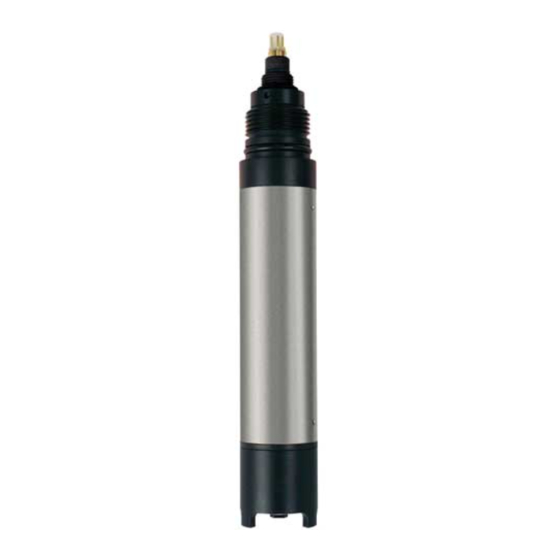
- Page 1 OxyMax W COS 71 BA 286C/07/en/07.01 Nr. 51506699 Sensor for Measuring Dissolved Oxygen Operating Instructions Quality made by Endress+Hauser ISO 9001...
-
Page 3: Table Of Contents
OxyMax W COS 71 Table of contents Safety instructions Commissioning ........ -
Page 4: Safety Instructions
• Measuring point faults may only be remedied by authorised and trained personnel. • If faults cannot be repaired, the measuring device must be taken out of service and secured against unintentional commissioning. • Repairs may only be carried out by the manufacturer or by the Endress+Hauser service organisation. Endress+Hauser... -
Page 5: Operational Safety
Return If the device requires repair, please send the sensor clean (see Seite 17) to the appropriate Endress+Hauser sales offices. Please use the original packaging where possible. Please add the filled in »Declaration of contamination« (copy the last but one page of this manual) to the packing of the sensor and add it also to the shipping documents. -
Page 6: Identification
– 1 sealing kit COY 31-OR with 3 O-rings – 6 polishing sheets • Operating Instructions BA 286C/07/en If you have questions, please contact your supplier or your nearest Endress+Hauser sales office (see the back page of this Operating Instructions). Endress+Hauser... -
Page 7: Installation
OxyMax W COS 71 3 Installation Installation Measuring device A complete measuring system comprises: • Oxygen sensor OxyMax W COS 71 • Oxygen transmitter Liquisys M COM 223/253-WX/WS Optional: • Flow assembly FlowFit W COA 260 • Junction box VS Fig. -
Page 8: Installation Conditions
3 Installation OxyMax W COS 71 Installation conditions 3.2.1 Installation dimensions Ø40 Fig. 3.2: Dimensions COS 71 Fig. 3.3: COS 71 with TOP 68 plug-in head and fixed cable version TOP 68 plug-in cable Endress+Hauser... -
Page 9: Installation Location And Position
OxyMax W COS 71 3 Installation Installation location and position The sensor can be installed up to the horizontal in an assembly, support or a suitable process connection (Fig. 3.4). Other angles are not permissible. Do not install the sensor overhead. - Page 10 3 Installation OxyMax W COS 71 Required total height for sensor installation or removal 540 mm Ø 60 Fig. 3.5: Flow assembly COA 260 Fig. 3.6: Bypass installation with manually actuated valves or solenoid valves Main line Pressing screw Medium return...
-
Page 11: Sensor Design And Functional Description
OxyMax W COS 71 3 Installation Sensor design and functional description 3.4.1 Design The sensor consists of the following function units: • Sensor body with integrated sensor electronics • Sensor head with gold cathode, counter electrode and reference electrode • Membrane cap with electrolyte •... - Page 12 3 Installation OxyMax W COS 71 3.4.2 Functional description Polarisation When the sensor is connected to the transmitter, a fixed external voltage is applied between the cathode and anode. The resulting polarisation current is indicated on a display on the transmitter. The current starts high but then drops over time. The sensor can only be calibrated when the display is stable.
-
Page 13: Post-Installation Check
OxyMax W COS 71 3 Installation Post-installation check After installing the sensor, carry out the following checks: Checks Remarks Membrane OK (visual inspection)? Replace membrane if there is a leak. Compliance with permissible sensor installation position? see Chapter 3.3 Sensor installed tightly in flow assembly? Avoid leakages. -
Page 14: Wiring
4 Wiring OxyMax W COS 71 Wiring Direct connection to the transmitter The sensor COS 71 is connected to the transmitter using a special measuring cable with SXP plug-in head (fig). Fig. 4.1: SXP plug-in head To connect the sensor to a field instrument COM 253-WX/WS plug in the sensor plug-in head into the SXB plug-in of the transmitter. -
Page 15: Post-Connection Check
OxyMax W COS 71 4 Wiring Junction box VS Fig. 4.2: Cable extension to a field instrument Fig. 4.3: Cable extension to a panel mounting COM 253-WX/WS via junction box VS instrument COM 253-WX/WS via junction box VS SXP plug-in head to COM 253-WX/WS... -
Page 16: Commissioning
5 Commissioning OxyMax W COS 71 Commissioning Function check Before the first commissioning, make sure of the following points: • That the sensor was correctly installed (Post-installation check, see Chapter 3.5) • That the electrical connection is correct (Post-connection check, see Chapter 4.3) Warning! Danger of medium escaping. -
Page 17: Calibration
OxyMax W COS 71 5 Commissioning Calibration Calibration is a means of adapting the transmitter to the characteristic values of the sen- sor. As no zero calibration is required for the sensor COS 71, a single-point calibration is carried out in the presence of oxygen. - Page 18 5 Commissioning OxyMax W COS 71 3. Determine: • L = [rel. air pressure at calibration] : [1013 hPa] • M = 1.02 for calibration in air M = 1.00 for calibration in air-saturated water 4. Calculate the calibration value: Calibration value = S •...
-
Page 19: Maintenance
Clean the sensor: • before every calibration • at regular intervals during operation as necessary. • before returning it to Endress+Hauser for repairs. Depending on the type of soiling, proceed as follows: Type of soiling Cleaning measure... -
Page 20: Regeneration
6 Maintenance OxyMax W COS 71 Regeneration Parts of the sensor will suffer wear and tear during operation. Suitable action can restore normal operating functionality. This action includes: Action Cause Cleaning the gold cathode Soiled or silver-plated gold cathode (Chap. 6.2.1) - Page 21 OxyMax W COS 71 6 Maintenance To replace the electrolyte, proceed as follows: 1. Remove the membrane cap (see Chap. 6.2.4). 2. Replace the electrolyte and, if necessary, the membrane cap. 3. Place the membrane cap back on the membrane body and screw the cap to the stop.
-
Page 22: Accessories
7 Accessories OxyMax W COS 71 Accessories Connection accessories • Junction box VS for extension with special measuring cable OMK. junction box for the extension of the connection between the sensor and the transmitter; Order No. 50001054 • Extension cable OMK Special extension cable between junction box VS and transmitter;... -
Page 23: Troubleshooting
OxyMax W COS 71 8 Troubleshooting Troubleshooting Troubleshooting instructions If any of the following problems occur, test the measuring device as indicated. Problem Test Remedial action No display, Mains voltage to the transmitter ? Connect mains voltage no sensor reaction... -
Page 24: Sensor Test
8 Troubleshooting OxyMax W COS 71 Sensor test " Caution! Only authorised and trained personnel may test the sensor. You will also require a multimeter (voltage, resistance). Then carry out the following to test the sensor: Test Measure Setpoint Voltage inspection... -
Page 25: Technical Data
OxyMax W COS 71 9 Technical data Technical data General specifications Manufacturer Endress+Hauser Product name OxyMax W COS 71 Environment Storage temperature filled with electrolyte: – 5 ... 50°C without electrolyte: –20 ... 60°C Process conditions Process temperature range –5 ... 50°C Process pressure range 10 bar max. -
Page 26: Index
Index OxyMax W COS 71 Index Accessories....... . 20 Maintenance....... 17 ACPV . - Page 27 Declaration of contamination Dear costumer, Because of legal determinations and for the safety of our employes and operating equipment we need this “Declaration of contamination” with your signature before your order can be handled. Please put the completely filled in declaration to the instrument and to the shipping documents in any case. Add also safety sheets and/or specific handling instructions if necessary.
- Page 28 Canada Philippines Poland Minsk ❑ Endress+Hauser Ltd. ❑ Endress+Hauser Philippines Inc. ❑ Endress+Hauser Polska Sp. z o.o. Tel. (0172) 263166, Fax (0172) 263111 Burlington, Ontario Metro Manila Raszyn Tel. (905) 6819292, Fax (905) 6819444 Tel. (2) 3723601-05, Fax (2) 4121944 Belgium / Luxembourg Tel.
Need help?
Do you have a question about the OxyMax W COS 71 and is the answer not in the manual?
Questions and answers