
Related Manuals for Dell OptiPlex 7090 Ultra


Summary of Contents for Dell OptiPlex 7090 Ultra
- Page 1 OptiPlex 7090 Ultra Service Manual Regulatory Model: D13U Regulatory Type: D13U002 August 2021 Rev. A01...
- Page 2 A WARNING indicates a potential for property damage, personal injury, or death. © 2021 Dell Inc. or its subsidiaries. All rights reserved. Dell, EMC, and other trademarks are trademarks of Dell Inc. or its subsidiaries. Other trademarks may be trademarks of their respective owners.
-
Page 3: Table Of Contents
Contents Chapter 1: Working on your computer................... 6 Safety instructions................................6 Before working inside your device..........................6 Safety precautions.................................7 Electrostatic discharge—ESD protection........................7 ESD field service kit ..............................8 Transporting sensitive components.......................... 9 After working inside your device..........................9 Chapter 2: Stands........................10 Fixed stand..................................10 Installing the device on a fixed stand........................ - Page 4 Installing the M.2 2230 solid-state drive....................... 99 Removing the M.2 2280 solid-state drive......................100 Installing the M.2 2280 solid-state drive......................101 Solid-state drive daughter board..........................102 Removing the daughter board..........................102 Installing the solid-state drive daughter board....................103 Cover....................................104 Removing the cover..............................104 Installing the cover..............................
- Page 5 Deleting or changing an existing system setup password................141 Clearing BIOS (System Setup) and System passwords..................142 Chapter 6: Troubleshooting....................... 143 Dell SupportAssist Pre-boot System Performance Check diagnostics.............. 143 Running the SupportAssist Pre-Boot System Performance Check.............. 143 Diagnostic LED................................. 144 Recovering the operating system..........................144...
-
Page 6: Chapter 1: Working On Your Computer
You should only perform troubleshooting and repairs as authorized or directed by the Dell technical assistance team. Damage due to servicing that is not authorized by Dell is not covered by your warranty. See the safety instructions that is shipped with the product or at www.dell.com/regulatory_compliance. -
Page 7: Safety Precautions
ESD protection is an increasing concern. Due to the increased density of semiconductors used in recent Dell products, the sensitivity to static damage is now higher than in previous Dell products. For this reason, some previously approved methods of handling parts are no longer applicable. -
Page 8: Esd Field Service Kit
It is recommended that all field service technicians use the traditional wired ESD grounding wrist strap and protective anti-static mat at all times when servicing Dell products. In addition, it is critical that technicians keep sensitive parts separate from all insulator parts while performing service and that they use anti-static bags for transporting sensitive components. -
Page 9: Transporting Sensitive Components
Transporting sensitive components When transporting ESD sensitive components such as replacement parts or parts to be returned to Dell, it is critical to place these parts in anti-static bags for safe transport. After working inside your device About this task After you complete any replacement procedure, ensure that you connect any external devices, cards, and cables before turning on your device. -
Page 10: Chapter 2: Stands
Stands Topics: • Fixed stand • Pro 1.0 Height-adjustable stand-HAS • Offset VESA mount • Pro 2 Height-adjustable stand-HAS • Wall Mount Fixed stand Installing the device on a fixed stand Steps 1. Align and insert the slots on the fixed stand into the tab on the stand base. 2. - Page 11 5. Slide and lift the cover to release it from the stand. 6. Remove the screw that secures the stand mounting bracket to the stand. 7. Lift the mounting bracket to release the hooks on the bracket from the slots on the stand. Stands...
- Page 12 8. To avoid any damage to the monitor, ensure that you place the monitor on a protective sheet. 9. Align the screws on the mounting bracket with the screw holes on the monitor. 10. Tighten the four captive screws to secure the mounting bracket to the monitor. Stands...
- Page 13 11. Select the height at which you want to mount the monitor and align the hooks on the mounting bracket with the slots on the stand. 12. Replace the screw to secure the fixed stand to the monitor. Stands...
- Page 14 13. Align the vents on the device with the vents on the stand cover. 14. Lower the device in the stand until you hear a click. 15. Connect the power, network, keyboard, mouse, and display cables to the device and to the power outlet. NOTE: To avoid any pinching or crimping of the cables while closing the stand cover, it is recommended that you route the cables as indicated in the image.
- Page 15 NOTE: All the cables and ports are used depending on the peripherals chosen and the configuration of the computer. 16. Slide the back cover, along with the device, into the stand until you hear a click. Stands...
- Page 16 17. Lock the device and the stand cover. Stands...
- Page 17 18. Press the power button to turn on the device. Stands...
-
Page 18: Removing The Device From A Fixed Stand
Removing the device from a fixed stand Prerequisites 1. Follow the procedure in before working inside your device. Steps 1. Unlock the device and the stand cover. Stands... - Page 19 2. Slide the release latch on the stand until you hear a click to release the stand cover. 3. Slide and lift the back cover to release it from the stand. Stands...
- Page 20 4. Disconnect the keyboard, mouse, network, power, and display cable from the device. NOTE: All the cables and ports are used depending on the peripherals chosen and the configuration of the computer. Stands...
- Page 21 5. Pull the retention latch that secures the device to the stand chassis. 6. Lift the device from the cover. 7. Press and hold the power button while the device is unplugged to ground the system board. NOTE: To avoid electrostatic discharge, ground yourself by using a wrist grounding strap or by periodically touching an unpainted metal surface at the same time as touching a connector on the back of the computer.
-
Page 22: Monitor Tilt Angle
Monitor tilt angle Pro 1.0 Height-adjustable stand-HAS Installing the device on a Pro 1 height-adjustable stand Steps 1. Align and insert the slots on the height-adjustable stand into the tab on the stand base. 2. Lift and tilt the stand base. 3. - Page 23 4. To avoid any damage to the monitor, ensure that you place the monitor on a protective sheet. 5. For installing the height-adjustable stand to the monitor: a. Align and insert the hooks on the mounting bracket on the stand into the slots on the monitor, until you hear a click. Stands...
- Page 24 6. For installing QR to VESA bracket for E-Series monitor or monitor without Quick Release support: a. Align the screw holes on the QR to VESA bracket with the screw holes on the monitor. b. Install the four screw spacers and the screws to secure the QR to VESA bracket to the monitor. c.
- Page 25 7. To release the stand cover, slide the release latch until you hear a click. 8. Slide and lift the cover to release it from the stand. 9. Align the vents on the device with the vents on the stand cover. 10.
- Page 26 11. Connect the power, network, keyboard, mouse, and display cables to the device and to the power outlet. NOTE: To avoid any pinching or crimping of the cables while closing the stand cover, it is recommended that you route the cables as indicated in the image. NOTE: All the cables and ports are used depending on the peripherals chosen and the configuration of the computer.
- Page 27 12. Slide the back cover, along with the device, into the stand until you hear a click. Stands...
- Page 28 13. Lock the device and the stand cover. Stands...
- Page 29 14. Press the power button to turn on the device. Stands...
-
Page 30: Removing The Device From Pro 1 Height-Adjustable Stand
Removing the device from Pro 1 height-adjustable stand Prerequisites 1. Follow the procedure in before working inside your device. Steps 1. Turn off your device. 2. Unlock the device and the stand cover. Stands... - Page 31 3. Slide the release latch on the stand until you hear a click to release the stand cover. 4. Slide and lift the back cover to release it from the stand. Stands...
- Page 32 5. Disconnect the keyboard, mouse, network, power, and display cable from the device. NOTE: All the cables and ports are used depending on the peripherals chosen and the configuration of the computer. Stands...
- Page 33 6. Pull the retention latch that secures the device to the stand chassis. 7. Lift the device from the cover. 8. Press and hold the power button while the device is unplugged to ground the system board. NOTE: To avoid electrostatic discharge, ground yourself by using a wrist grounding strap or by periodically touching an unpainted metal surface at the same time as touching a connector on the back of the computer.
-
Page 34: Stand Tilt, Pivot, And Swivel Images
Stand tilt, pivot, and swivel images Offset VESA mount Installing device on offset VESA mount Steps 1. Align the screw holes on the device with the screw holes on the offset VESA mount. 2. Install the four screws to secure the device to the offset VESA mount. Stands... - Page 35 3. To avoid any damage to the monitor, ensure that you place the monitor on a protective sheet. 4. Align the screw holes on the offset VESA mount with the screw holes on the monitor. 5. Install the four screw spacers and the screws to secure the offset VESA mount to the monitor. Stands...
- Page 36 6. Insert the hooks on the mounting bracket of the monitor arm stand into the slots on the offset VESA mount on the monitor. 7. Lower the monitor on the monitor arm stand until you hear a click. Stands...
- Page 37 8. To install the offset VESA mount on a Dell E-Series monitor: a. Align and install the four screws to secure the device to the offset VESA mount. Stands...
- Page 38 b. Remove the VESA cover from the back of the monitor and secure the offset VESA mount along with the device to the monitor. Stands...
- Page 39 Stands...
- Page 40 Stands...
-
Page 41: Removing The Device From Offset Vesa Mount
NOTE: While orienting the monitor horizontally, route the security lock cable to the right side of the device to avoid any impact to WLAN performance. Removing the device from offset VESA mount Prerequisites 1. Follow the procedure in before working inside your device. - Page 42 7. Lift the offset VESA mount from the monitor. 8. Remove the four screws that secure the device to the offset VESA mount. 9. Lift the device away from the offset VESA mount. 10. Press and hold the power button while the device is unplugged to ground the system board. Stands...
-
Page 43: Pro 2 Height-Adjustable Stand-Has
NOTE: To avoid electrostatic discharge, ground yourself by using a wrist grounding strap or by periodically touching an unpainted metal surface at the same time as touching a connector on the back of the computer. Pro 2 Height-adjustable stand-HAS Installing the device on a Pro 2 height-adjustable stand Steps 1. - Page 44 4. To avoid any damage to the monitor, ensure that you place the monitor on a protective sheet. 5. For installing the height-adjustable stand to the monitor: a. Align and insert the hooks on the mounting bracket on the stand into the slots on the monitor, until you hear a click. Stands...
- Page 45 Stands...
- Page 46 6. For installing QR to VESA bracket for E-Series monitor or monitor without Quick Release support: a. Align the screw holes on the QR to VESA bracket with the screw holes on the monitor. b. Install the four screw spacers and the screws to secure the QR to VESA bracket to the monitor. c.
- Page 47 Stands...
- Page 48 7. To release the stand cover, press the button on the side of the stand chassis. 8. Slide and lift the cover to release it from the stand. Stands...
- Page 49 9. Slide and release the inner bar on the lower edge of the stand cover. Stands...
- Page 50 10. Align the vents on the device with the vents on the stand cover and slide the device in the cover. Stands...
- Page 51 11. Slide the inner bar back to the lower edge of the stand cover to lock the device to the cover. Stands...
- Page 52 12. Connect the power, network, keyboard, mouse, and display cables to the device and to the power outlet. Stands...
- Page 53 13. To avoid any pinching or crimping of the cables while closing the stand cover, it is recommended that you route the cables as indicated in the image. NOTE: All the cables and ports are used depending on the peripherals chosen and the configuration of the computer. Standard Height Adjustable Stand Stands...
- Page 54 Large Height Adjustable Stand Stands...
- Page 55 14. Slide the stand cover, along with the device, into the stand until you hear a click. Stands...
- Page 56 15. Lock the device and the stand cover. Stands...
- Page 57 16. Press the power button to turn on the device. Stands...
-
Page 58: Removing The Device From A Pro 2 Height-Adjustable Stand
Removing the device from a Pro 2 height-adjustable stand Prerequisites 1. Follow the procedure in before working inside your device. Steps 1. Turn off your device. 2. Press the button on the side of the stand chassis, to release the stand cover. 3. - Page 59 4. Disconnect the keyboard, mouse, network, power, and display cable from the device. Stands...
- Page 60 5. Slide and release the inner bar on the lower edge of the stand cover that secures the device to the stand chassis. Stands...
- Page 61 6. Slide and remove the device from the cover. 7. Slide the inner bar back to the lower edge of the stand cover. Stands...
-
Page 62: Stand Tilt, Pivot, And Swivel Images
8. Slide the stand cover back to the stand. 9. Press and hold the power button while the device is unplugged to ground the system board. NOTE: To avoid electrostatic discharge, ground yourself by using a wrist grounding strap or by periodically touching an unpainted metal surface at the same time as touching a connector on the back of the computer. - Page 63 For 30-inch to 32-inch monitor (Large height adjustable stand): Stands...
- Page 64 For monitors > 32-inch (Large height adjustable stand): Stands...
-
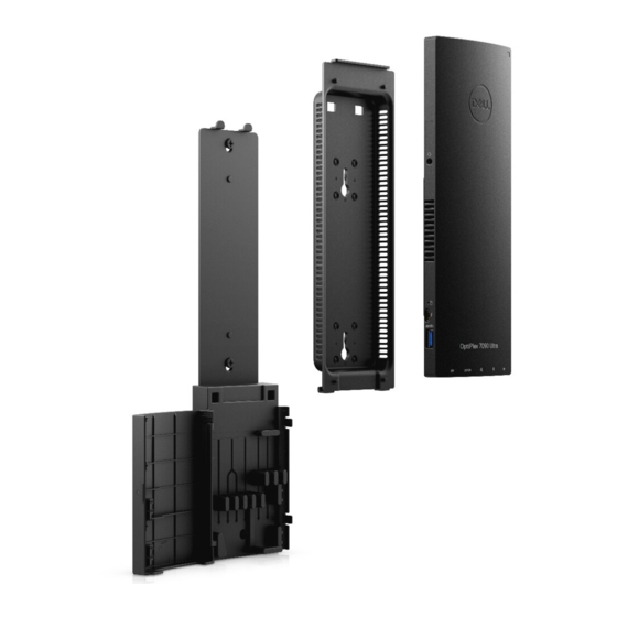
Page 65: Wall Mount
Wall Mount Installing device on Wall Mount Steps 1. Full Function a. Press the release button to open the cable cover. b. Align the screw holes on the wall mount in the wall and mark them against the wall using a pencil. Stands... - Page 66 c. Drill the screw marks on the wall and insert the three screw anchors into the screw holes in the wall. Stands...
- Page 67 d. Align the screw holes on the wall mount with the screw holes on the wall and install the three screws to secure the wall mount in the wall. Stands...
- Page 68 e. Align the screw holes on the device with the screw holes on the wall mount bracket. f. Install the four screws to secure the device to the wall mount bracket. Stands...
- Page 69 g. Insert the hooks on the mounting bracket of the wall mount into the slots on the wall mount bracket module. h. Align and insert the hooks on the wall mount bracket module into the slots on the wall mount until it clicks into place Stands...
- Page 70 Connect the power, network, keyboard, mouse, and display cables to the device and to the power outlet. Stands...
- Page 71 To avoid any pinching or crimping of the cables while closing the stand cover, it is recommended that you route the cables as indicated in the image. NOTE: All the cables and ports are used depending on the peripherals chosen and the configuration of the computer. Stands...
- Page 72 k. Close the stand cover. Stands...
- Page 73 Lock the device and the stand cover. Stands...
- Page 74 2. Simple Function a. Align the screw holes on the wall mount in the wall and mark them using a pencil. Stands...
- Page 75 b. Drill the screw marks on the wall and insert the two screws into the screw holes in the wall. Stands...
- Page 76 c. Align the screw holes on the device with the screw holes on the wall mount bracket. d. Install the four screws to secure the device to the wall mount bracket. Stands...
- Page 77 e. Connect the power, network, keyboard, mouse, and display cables to the device and to the power outlet. Stands...
- Page 78 f. Align the screws on the wall with the retention clips on the wall mount bracket module. g. Mount the wall mount bracket module in the screws on the wall. Stands...
- Page 79 h. Press the power button to turn on the device. Stands...
-
Page 80: Removing The Device From Wall Mount
Removing the device from Wall Mount Prerequisites 1. Follow the procedure in before working inside your device. Steps 1. Turn off your device. 2. For full function wall mount: a. Unlock the wall mount module. Stands... - Page 81 b. Open the wall mount cover. Stands...
- Page 82 c. Disconnect the keyboard, mouse, network, power, and display cable from the device. Stands...
- Page 83 d. Snap open the wall mount bracket module from the slots on the wall mount. Stands...
- Page 84 e. Remove the four screws that secure the device to the wall mount bracket. f. Lift the device away from the wall mount bracket. Stands...
- Page 85 3. For simple function wall mount: a. Unmount the wall mount bracket module from the wall. b. Disconnect the keyboard, mouse, network, power adapter, and display cable from the device. Stands...
- Page 86 c. Remove the four screws that secure the device to the wall mount bracket. d. Lift the device away from the wall mount bracket. Stands...
- Page 87 4. Press and hold the power button while the device is unplugged to ground the system board. NOTE: To avoid electrostatic discharge, ground yourself by using a wrist grounding strap or by periodically touching an unpainted metal surface at the same time as touching a connector on the back of the computer. Stands...
-
Page 88: Chapter 3: Removing And Installing Components
Removing and installing components NOTE: The images in this document may differ from your computer depending on the configuration you ordered. Topics: • Recommended tools • Screw List • Major components of your system • Hard-drive assembly • Hard-drive bracket •... - Page 89 Table 1. Screw Size List (continued) Component Screw type Quantity Image Hard-drive assembly (or non M2x3 Hard-drive assembly) or SSD 2230/2280 cover M.2 WLAN card M2x3.5 M.2 2230 Solid-state drive or M2x3.5 EMMC M.2 (Option 2230 SSD or M2x3.5 2280 SSD) Daughter board M2x3.5 M.2 Standoff...
-
Page 90: Major Components Of Your System
Major components of your system 1. Cover Removing and installing components... -
Page 91: Hard-Drive Assembly
14. Coin-cell battery NOTE: Dell provides a list of components and their part numbers for the original system configuration purchased. These parts are available according to warranty coverages purchased by the customer. Contact your Dell sales representative for purchase options. -
Page 92: Installing The Hard-Drive Assembly
Steps 1. Remove the (M2x3) screw that secures the hard-drive assembly to the chassis. 2. Turn the hard-drive assembly to access the hard-drive cable. 3. Open the latch and disconnect the hard-drive cable from the connector on the system board. 4. - Page 93 About this task The figure indicates the location of the hard-drive assembly module and provides a visual representation of the installation procedure. Steps 1. Place the hard-drive assembly on the cover. 2. Route the hard-drive cable through the routing guide on the chassis. 3.
-
Page 94: Hard-Drive Bracket
Hard-drive bracket Removing the hard-drive bracket Prerequisites 1. Follow the procedure in before working inside your device. 2. Remove the device from fixed stand/Pro 1 height-adjustable stand/Offset VESA mount/Pro 2 height-adjustable stand/Wall mount. 3. Remove the hard-drive assembly. About this task Steps Pull the rubber tab on the protective sleeve and lift the hard-drive module out from the hard-drive bracket. -
Page 95: Hard Drive
About this task Steps 1. Align and place the hard drive on the bracket. 2. Gently push the hard-drive into the bracket. Next steps 1. Install the hard-drive assembly. 2. Install the device on Fixed stand/Pro 1 height-adjustable stand/Offset VESA mount/Pro 2 height-adjustable stand/Wall mount. -
Page 96: Installing The Hard Drive
Steps 1. Disconnect the hard-drive cable from the connector on the hard drive. 2. Release the protective sleeve from the hard-drive. 3. Gently pull the hard-drive out of the protective sleeve. Installing the hard drive Prerequisites If you are replacing a component, remove the existing component before performing the installation procedure. About this task The figure indicates the location of the hard-drive module and provides a visual representation of the installation procedure. -
Page 97: Solid-State Drive In The Hard-Drive Bay
Steps 1. Insert the hard drive into the protective sleeve. NOTE: Ensure to match the mark on the protective sleeve with the hard drive PIN and connector location. 2. Pull the protective sleeves along the hard-drive edges. 3. Connect the hard-drive cable to the connector on the hard drive. Next steps 1. -
Page 98: Removing The M.2 2230 Solid-State Drive
Removing the M.2 2230 solid-state drive For systems with solid-state drive in the hard drive bay will not support hard drive. Prerequisites 1. Follow the procedure in before working inside your device. 2. Remove the device from fixed stand/Pro 1 height-adjustable stand/Offset VESA mount/Pro 2 height-adjustable stand/Wall mount. -
Page 99: Installing The M.2 2230 Solid-State Drive
Installing the M.2 2230 solid-state drive For systems with solid-state drive in the hard drive bay will not support hard drive. Prerequisites If you are replacing a component, remove the existing component before performing the installation procedure. About this task The figure indicates the location of the M.2 2230 solid-state drive and provides a visual representation of the installation procedure. -
Page 100: Removing The M.2 2280 Solid-State Drive
Next steps 1. Install the device on Fixed stand/Pro 1 height-adjustable stand/Offset VESA mount/Pro 2 height-adjustable stand/Wall mount. 2. Follow the procedure in after working on your device. Removing the M.2 2280 solid-state drive For systems with solid-state drive in the hard drive bay will not support hard drive. Prerequisites 1. -
Page 101: Installing The M.2 2280 Solid-State Drive
Steps 1. Remove the (M2x3) screw that secures the solid-state drive cover to the chassis. 2. Turn the solid-state drive cover and remove it from the chassis to access the M.2 2280 solid-state drive. 3. Remove the (M2x3.5) screw to that secures the M.2 2280 solid-state drive to the chassis. 4. -
Page 102: Solid-State Drive Daughter Board
Steps 1. Align the notch on the M.2 2280 solid-state drive with the tab on the daughter board and slide the M.2 2280 solid-state drive at an angle into the slot. 2. Replace the (M2x3.5) screw to secure the M.2 2280 solid-state drive to the chassis. 3. -
Page 103: Installing The Solid-State Drive Daughter Board
Steps 1. Remove the two (M2x3.5) screws that secure the solid-state drive daughter board to the chassis. 2. Disconnect the solid-state drive daughter board from the connector in the system board and lift it from the chassis. Installing the solid-state drive daughter board For systems with solid-state drive in the hard drive bay will not support the hard drive. -
Page 104: Cover
Cover Removing the cover Prerequisites 1. Follow the procedure in before working inside your device. 2. Remove the device from fixed stand/Pro 1 height-adjustable stand/Offset VESA mount/Pro 2 height-adjustable stand/Wall mount. About this task The figure indicates the location of the cover and provides a visual representation of the removal procedure. Steps Slide and lift the cover to release it from the chassis. -
Page 105: Installing The Cover
Installing the cover Prerequisites If you are replacing a component, remove the existing component before performing the installation procedure. About this task The figure indicates the location of the cover and provides a visual representation of the installation procedure. Steps 1. -
Page 106: Memory Module
Memory module Removing the memory module Prerequisites 1. Follow the procedure in before working inside your device. 2. Remove the device from fixed stand/Pro 1 height-adjustable stand/Offset VESA mount/Pro 2 height-adjustable stand/Wall mount. 3. Remove the cover. About this task The figure indicates the location of the memory module and provides a visual representation of the removal procedure. -
Page 107: Installing The Memory Module
Installing the memory module Prerequisites If you are replacing a component, remove the existing component before performing the installation procedure. About this task The figure indicates the location of the memory module and provides a visual representation of the installation procedure. Steps 1. -
Page 108: Wlan Card
Next steps 1. Install the cover. 2. Install the device on Fixed stand/Pro 1 height-adjustable stand/Offset VESA mount/Pro 2 height-adjustable stand/Wall mount. 3. Follow the procedure in after working on your device. WLAN card Removing the WLAN card Prerequisites 1. Follow the procedure in before working inside your device. -
Page 109: Installing The Wlan Card
Steps 1. Remove the (M2x3.5) screw that secures the WLAN bracket to the system board. 2. Slide and lift the WLAN bracket. 3. Disconnect the WLAN antenna cables from the WLAN card. 4. Lift and slide the WLAN card from the WLAN connector on the system board. Installing the WLAN card Prerequisites If you are replacing a component, remove the existing component before performing the installation procedure. -
Page 110: Internal Solid-State Drive
Table 2. Antenna-cable color scheme Connectors on the wireless card Antenna-cable color Main (white triangle) White Auxiliary (black triangle) Black 2. Align and place the WLAN card bracket to secure the WLAN antenna cables to the WLAN card. 3. Align the notch on the WLAN card with the WLAN connector and insert the WLAN card at an angle into the WLAN card slot. 4. -
Page 111: Installing The Solid-State Drive
Steps 1. Remove the (M2x3.5) screw that secures the solid-state drive module to the connector on the system board. 2. Lift and slide the solid-state drive module out from the M.2 slot. 3. Peel the solid-state drive thermal pad from the system board. Installing the solid-state drive Prerequisites If you are replacing a component, remove the existing component before performing the installation procedure. - Page 112 Steps 1. Align and adhere the SSD thermal pad in the mark on the system board. NOTE: Check the adhesive direction before adhering it to the system board. 2. Align the notch on the solid-state drive module with the connector on the system board and slide the solid-state drive at an angle into the slot.
-
Page 113: Emmc Storage Module
eMMC Storage module For computers with eMMC module in M.2 2230 SSD slot. Removing the eMMC storage module Prerequisites 1. Follow the procedure in before working inside your device. 2. Remove the device from fixed stand/Pro 1 height-adjustable stand/Offset VESA mount/Pro 2 height-adjustable stand/Wall mount. -
Page 114: System Fan
Steps 1. Align the notch on the eMMC storage module with the connector on the system board and slide the eMMC storage module at an angle into the slot. 2. Replace the (M2x3.5) screw to secure the eMMC storage module to the system board. Next steps 1. -
Page 115: Installing The System Fan
Steps 1. Release the system fan from the retention tab on the fan tray. 2. Disconnect the system fan cable from the connector on the system board. 3. Slide the system fan out from the guiding rails on the heat-sink bracket. Installing the system fan Prerequisites If you are replacing a component, remove the existing component before performing the installation procedure. -
Page 116: Power Button
Steps 1. Connect the system fan cable to the connector on the system board. 2. Align the tabs on the system fan with the guiding rails on the heat-sink bracket. 3. Press the system fan down into the fan tray until it clicks into place. Next steps 1. -
Page 117: Installing The Power Button
Steps 1. Disconnect the power-button cable from the connector on the system board. 2. Unroute the power-button cable from the routing guide. NOTE: Observe the routing of the power-button cable inside the chassis as you remove them. Route the cable properly when you replace the component to prevent the cable from being pinched or crimped. - Page 118 Steps 1. Place the power button into the slot on the chassis. 2. Replace the (M2x3) screw to secure the power button to the chassis. 3. Route the power button cable through the routing guides on the chassis. 4. Connect the power-button cable to the connector on the system board. Next steps 1.
-
Page 119: Coin-Cell Battery
Coin-cell battery Removing the coin-cell battery Prerequisites 1. Follow the procedure in before working inside your device. 2. Remove the device from fixed stand/Pro 1 height-adjustable stand/Offset VESA mount/Pro 2 height-adjustable stand/Wall mount. 3. Remove the cover. 4. Remove the system fan. -
Page 120: Installing The Coin-Cell Battery
NOTE: Observe the routing of the coin-cell battery cable inside the chassis as you remove them. Route the cable properly when you replace the component to prevent the cable from being pinched or crimped. 3. Release the coin-cell retention clip from the securing hook and turn the clip to the other side to access the coin-cell battery. 4. -
Page 121: System Board
4. Route the coin-cell battery cable through the routing guide. 5. Connect the coin-cell battery cable to the connector on the system board. Next steps 1. Install the system fan. 2. Install the cover. 3. Install the device on Fixed stand/Pro 1 height-adjustable stand/Offset VESA mount/Pro 2 height-adjustable stand/Wall mount. -
Page 122: Installing The System Board
Steps 1. Disconnect the power-button cable and the coin-cell battery cable from the connectors on the system board. 2. Unroute the power-button cable and the coin-cell battery cable from the routing guides. 3. Unroute the WLAN antenna cables from the routing guides. NOTE: Observe the routing of the WLAN antenna cables inside the chassis as you remove them. - Page 123 Steps 1. Align the connectors on the system board with the connector slots on the chassis. NOTE: The system board is installed along with the heat-sink connected to it. 2. Gently slide the system board into the chassis. Removing and installing components...
-
Page 124: Heat-Sink
3. Tighten the (M2x3) captive screw and replace the four (M2x3) screws to secure the system board to the chassis. 4. Route the power-button cable and the coin-cell battery cable through the routing guides. 5. Connect the power-button cable and the coin-cell battery cable to the connectors on the system board. 6. -
Page 125: Installing The Heat-Sink
Steps 1. In sequential order (as indicated on the heat sink), loosen the four captive screws that secure the heat sink to the system board. 2. Lift the heat-sink away from the system board. Installing the heat-sink Prerequisites If you are replacing a component, remove the existing component before performing the installation procedure. About this task The figure indicates the location of the heat-sink and provides a visual representation of the installation procedure. - Page 126 Steps 1. Align the screws on the heat-sink with the screw holes on the system board. 2. In sequential order (as indicated on the heat sink), tighten the four captive screws that secure the heat sink to the system board. Next steps 1.
-
Page 127: Replacing The Chassis
Replacing the chassis Prerequisites 1. Follow the procedure in before working inside your device. 2. Remove the device from fixed stand/Pro 1 height-adjustable stand/Offset VESA mount/Pro 2 height-adjustable stand/Wall mount. 3. Remove the hard-drive assembly. NOTE: For systems with solid-state drive module in hard-drive bay ●... -
Page 128: Chapter 4: Software
This chapter details the supported operating systems along with instructions on how to install the drivers. Topics: • Drivers and downloads Drivers and downloads When troubleshooting, downloading or installing drivers it is recommended that you read the Dell Knowledge Based article, Drivers and Downloads FAQ 000123347. Software... -
Page 129: Chapter 5: System Setup
Boot menu Press <F12> when the Dell logo appears to initiate a one-time boot menu with a list of the valid boot devices for the system. Diagnostics and BIOS Setup options are also included in this menu. The devices listed on the boot menu depend on the bootable devices in the system. -
Page 130: Navigation Keys
Boot sequence enables you to bypass the System Setup–defined boot device order and boot directly to a specific device (for example: optical drive or hard drive). During the Power-on Self-Test (POST), when the Dell logo appears, you can: ● Access System Setup by pressing F2 key ●... - Page 131 Table 3. System setup options—System information menu (continued) Overview Processor Information Processor Type Displays the processor type. Maximum Clock Speed Displays the maximum processor clock speed. Minimum Clock Speed Displays the minimum processor clock speed. Current Clock Speed Displays the current processor clock speed. Core Count Displays the number of cores on the processor.
- Page 132 Table 4. System setup options—Boot Configuration menu (continued) Boot Configuration Secure Boot Mode Enable or disable to change the secure boot mode options. By default, the Deployed Mode is enabled. Expert Key Management Enable Custom Mode Enable or disable custom mode. By default, the custom mode option is not enabled.
- Page 133 Table 6. System setup options—Storage menu (continued) Storage By default, the Enable SMART Reporting option is not enabled. Drive Information SATA-1 Type Displays the SATA type information of the system. Device Displays the SATA device information of the system. M.2 PCIe SSD Type Displays the M.2 PCIe SSD type information of the system.
- Page 134 Table 9. System setup options—Power menu Power USB Wake Support Enable USB Wake Support When enabled, connecting Dell USB devices will wake the system from standby. By default, the option is enabled. AC Behaviour AC Recovery Allows to determine what happens when AC power is restored after an unexpected loss of AC power.
- Page 135 Table 10. System setup options—Security menu (continued) Security Total Memory Encryption Enable or disable you to protect memory from physical attacks including freeze spray, probing DDR to read the cycles, and others. By default, the Total Memory Encryption option is disabled. Chassis intrusion Controls the chassis intrusion feature.
- Page 136 Dell Auto operating system Recovery Controls the automatic boot flow for SupportAssist System Resolution Console Threshold and for Dell operating system Recovery Tool. By default, the threshold value is set to 2. Table 13. System setup options—System Management menu System Management Service Tag Display the Service Tag of the system.
- Page 137 Table 13. System setup options—System Management menu (continued) System Management Watchdog Timer Support Enable or disable the Watchdog Timer Feature. By default, the option is disabled. Wake on LAN Wake on LAN Enable or disable the system to power on by special LAN signals when it receives a wakeup signal from the WLAN.
- Page 138 Table 15. System setup options—Pre-boot Behavior menu (continued) Pre-boot Behavior Extend BIOS POST Time Set the BIOS POST time. By default, the 0 seconds option is enabled. MAC Address Pass-Through Replaces the external NIC MAC address with the selected MAC address from the system.
-
Page 139: Updating The Bios
Steps 1. Go to www.dell.com/support. 2. Click Product support. In the Search support box, enter the Service Tag of your computer, and then click Search. NOTE: If you do not have the Service Tag, use the SupportAssist feature to automatically identify your computer. You can also use the product ID or manually browse for your computer model. -
Page 140: Updating The Bios From The F12 One-Time Boot Menu
One-Time boot menu on the computer. Most of the Dell computers built after 2012 have this capability, and you can confirm by booting your computer to the F12 One-Time Boot Menu to see if BIOS FLASH UPDATE is listed as a boot option for your computer. If the option is listed, then the BIOS supports this BIOS update option. -
Page 141: System And Setup Password
System and setup password Table 19. System and setup password Password type Description System password Password that you must enter to log in to your system. Setup password Password that you must enter to access and make changes to the BIOS settings of your computer. You can create a system password and a setup password to secure your computer. -
Page 142: Clearing Bios (System Setup) And System Passwords
Clearing BIOS (System Setup) and System passwords About this task To clear the system or BIOS passwords, contact Dell technical support as described at www.dell.com/contactdell. NOTE: For information on how to reset Windows or application passwords, refer to the documentation accompanying Windows or your application. -
Page 143: Chapter 6: Troubleshooting
Check diagnostics About this task SupportAssist diagnostics (also known as system diagnostics) performs a complete check of your hardware. The Dell SupportAssist Pre-boot System Performance Check diagnostics is embedded with the BIOS and is launched by the BIOS internally. The embedded system diagnostics provides a set of options for particular devices or device groups allowing you to: ●... -
Page 144: Diagnostic Led
It enables you to diagnose hardware issues, repair your computer, back up your files, or restore your computer to its factory state. You can also download it from the Dell Support website to troubleshoot and fix your computer when it fails to boot into their primary operating system due to software or hardware failures. -
Page 145: Real-Time Clock (Rtc Reset)
Real-Time Clock (RTC Reset) The Real Time Clock (RTC) reset function allows you or the service technician to recover Dell systems from No POST/No Power/No Boot situations. The legacy jumper enabled RTC reset has been retired on these models. Start the RTC reset with the system powered off and connected to AC power. Press and hold the power button for 20 seconds. -
Page 146: Chapter 7: Getting Help And Contacting Dell
Getting help and contacting Dell Self-help resources You can get information and help on Dell products and services using these self-help resources: Table 21. Self-help resources Self-help resources Resource location Information about Dell products and services www.dell.com My Dell app...
Need help?
Do you have a question about the OptiPlex 7090 Ultra and is the answer not in the manual?
Questions and answers