Table of Contents
Advertisement
Quick Links
Advertisement
Table of Contents

Related Manuals for INVT BD30KTR-P


Summary of Contents for INVT BD30KTR-P
- Page 1 User Manual BD 30-150kW-P Inverter...
-
Page 2: Table Of Contents
CONTENTS About This Manual ......................3 1.1Preface ........................3 1.2Applicable products ....................3 1.3 Content abstract......................3 1.4 Symbols ........................3 Safety Instructions ......................5 2.1 Personnel Requirements ................... 5 2.2 Safety Warning Operation ..................5 2.3 Device Identification Protection................. 5 2.4 Electricity Safety Matters ................... - Page 3 5.3 Installation Preparation ................... 16 5.4 Machine Transportation ..................16 5.5 Location and Fixation ....................19 5.6 Design And Installation Of Air Ducts ................ 20 Electrical Installation Guidance ..................23 6.1 Cable Requirements ....................23 6.2 Connection Terminal ....................24 6.3 Wiring Specification ....................
-
Page 4: About This Manual
We also invite you to put forward more valuable suggestions on the product performance and function. 1.2Applicable products This manual is applicable to the product types as follows: Type AC Rated Power PV Rated Power Max AC Power BD30KTR-P 30KVA 30/60Kwp 33KVA BD50KTR-P 50KVA 60/120Kwp 55KVA... - Page 5 WARNING "Warning" indicates that there is a moderate potential hazard which, if not avoided, may result in death or serious injury. CAUTION "Caution" indicates that there is a low potential hazard which, if not avoided, may result in moderate or minor injury. NOTE "Note"...
-
Page 6: Safety Instructions
Safety Instructions 2.1 Personnel Requirements Only professional electricians or qualified personnel can operate the product. Operators should be fully familiar with the structure and working principle of the whole energy storage system. Operators should be fully familiar with this manual " BD 30-150kW-P Energy Storage Inverter User Manual"... -
Page 7: Electricity Safety Matters
2.4 Electricity Safety Matters 2.4.1 Electrical safety There is a lethal high voltage inside the product!! Do not touch terminals or conductors connected to power network circuits. Attention should be paid to all instructions or safety instructions for connection to the power grid and to the warning signs on the products. -
Page 8: On-Line Test Specification
2.6 On-line test specification 2.6.1 On-line Test There is a high voltage in the equipment. Accidental contact may lead to fatal shock hazard. Therefore, in live measurement, it should:: Ensure adequate levels of protection (such as wearing insulating gloves, insulating shoes, etc.). -
Page 9: Product Scrapping
2.9 Product Scrapping When the energy storage inverter needs to be discarded, it can not be treated as conventional waste, we will accept this product as per W and there may be a handling fee. Alternatively contact the local authorized professional recycling agency. 2.10 Other Considerations The following protective or emergency measures shall be taken according to the actual operation summary:... -
Page 10: Product Introduction
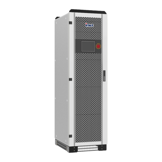
Product introduction 3.1 Product Appearance The appearance and external components of the energy storage inverter are described as follows BD30KTR-P BD100KTR-P BD50KTR-P BD150KTR-P High Voltage Electricity Danger! When pressing the emergency shutdown button, the AC/DC connection terminal of the energy storage inverter is still live! ... -
Page 11: Communication Solutions
output is turned into sine wave voltage via the LC filter, then goes through the isolated boost of three-phase transformer and then is incorporated into the grid power generation or becomes off-grid power supply to the load. Main circuit schematic inside the energy storage inverter is as shown in the figure below. 3.3 Communication Solutions 3.3.1Communication Scheme of Upper Computer The energy storage inverter communicates with the host computer through RS485/RS232... - Page 12 3.3.3 BMS Communication scheme Through CAN/RS485 communication line, energy storage inverter can communicate with BMS to realize data transmission. CAN/RS485 Figure3-8 BMS transmits data through CAN...
-
Page 13: Inverter Mode And Function
Inverter Mode and Function 4.1 Model Introduction 4.1.1 Self-use with grid The power generated from PV will be used to supply the local loads firstly, then to charge the battery , the redundant power will export to the public grid. 4.1.2 Self-use with generator ①... -
Page 14: Energy Storage Inverter Function
④ when the battery is full, turn off the generator automatically, BD 30-150kW-P transfer to ① mode 4.1.3 Maintenance mode 4.2 Energy Storage Inverter Function 4.2.1 Overheating And Cooling Operation The inverter operates at set power when IGBT junction temperature is less than 105 C. ... -
Page 15: Introduction Of Inverter Status
4.3Introduction of Inverter Status There are six states of energy storage inverter, as shown in Table 4-1 below. Table 4-1 Status and Description Status Description operation Normal operation of energy storage inverter。 When the inverter receives standby instructions from the LCD screen or the host computer, it turns to standby state in shutdown or operation mode. -
Page 16: Mechanical Installation Guidance
Mechanical Installation Guidance 5.1 Precautions Before Installation Installation of this series of energy storage inverters requires simultaneous operation of at least two qualified personnel, and all electrical installations must conform to local electrical installation standards. When installing, do not touch other parts of the cabinet except the terminal. ... -
Page 17: Installation Preparation
5.3 Installation Preparation 5.3.1 Packaging Inspection Before installation, it is necessary to check whether the equipment is damaged. If any transportation damage is found, please contact the transportation company. and provide photos of the damage. 5.3.2Delivery Checklist According to the packing list in the packing box, check whether all the parts delivered are complete or not: transportation Table 5-1 Delivery list project... - Page 18 description of inverter packaging labels is shown in tables 5-4 and 5-5. Table 5-4 Description of Packing Parameters Name Explain MODEL Inverter Model SIZE Outer packing dimensions Net weight of inverter Gross Weight, Inverter Containing Outer Packaging Table 5-5 Graphical description of packing marks Sign Describe Front-up, no transverse, tilt or inversion of inverter...
- Page 19 Figure 5-2 Packaged Handling Figure 5-3 Unpackaged Handling...
-
Page 20: Location And Fixation
The mechanical dimensions of each type of BD 30-150kW-P inverter are shown in Table 5-6 below. For more parameters, please refer to Appendix 1. Users can design and install according to this data. Table 5-6 Dimensions of BD 30-150kW-P Model Size(W×D×H) 800×800×1900(mm) BD30KTR-P 800×800×1900(mm) BD50KTR-P 1200×800×2050(mm) BD100KTR-P 1200×800×2050(mm) BD150KTR-P 5.5.3 Base Mounting... -
Page 21: Design And Installation Of Air Ducts
≥1000mm Cover plate Embedded 10# Channel Steel Cabinet Base Fixed with Channel Steel Fig. 5-5 Base mounting and fixing In the manufacture of channel anchors, it is necessary to design the positioning hole with the base at the bottom of the inverter. The bottom section of each model is shown in the following figures (mm). - Page 22 Figure 5-9 Schematic diagram of inverter external duct Specific requirements for adding air ducts to inverters are as follows: Requirements do not reduce cabinet ventilation by adding ducts The interface between air duct and inverter cabinet is well sealed. ...
- Page 23 Figure 5-12 500 kW/630 KW Vent Size...
-
Page 24: Electrical Installation Guidance
Electrical Installation Guidance 6.1 Cable Requirements According to the capacity allocation requirement of single BD 30-150kW-P inverter, it is suggested that the current passing through 1mm^ 2 conductor should be no more than 3A, and the same size and type of conductor should be selected for the connection on the same side. -
Page 25: Connection Terminal
The equipment does not have external cables. The above cable recommendation table is not provided by inverters. Users are requested to provide their own cables according to relevant needs. CAUTION All external cables are connected to the corresponding position after entering the equipment through the bottom entry and exit holes. -
Page 26: Fixation And Protection Of Connecting Cables
6.4 Fixation and Protection of Connecting Cables 6.4.1 Cable Fixation In order to prevent loosening of the copper nose, causing poor contact, or increasing contact resistance leading to fever or even fire, it is necessary to ensure that the screw fastening the terminal meets the torque requirements listed in Table 6-4: Table 6-4 Screw dimensions and required torques Screw size... -
Page 27: Dc Side Wiring
6.5.2 Installation Of Lower Fender BD 30-150kW-P inverters have lower fencing boards at the bottom of front, back, left and right. They are packaged and placed at the bottom of the packaging box. Before installation, all lower fencing boards of the inverter must be removed and put out. After the inverter is positioned and the screw is locked, the lower fencing boards shall be installed. - Page 28 Any DC input voltage exceeding this limit may cause damage to the inverter. Damage and loss of equipment caused in this case do not fall within the scope of quality assurance. WARNING Fixed screw and other parts used for wiring have been installed at the corresponding wiring terminals when the equipment is delivered.
-
Page 29: Ac Side Wiring
6.7 AC Side Wiring 6.7.1AC Connection All models of this series energy storage inverters have grid connection. Only those with bypass need to consider bypass connection. Their corresponding relations are shown in the table below. Refer to Section 6.5 for the access location of copper bars. Table 6-6 Corresponding Table 6-7 Load connection Relations of Power Grid... -
Page 30: Test Run
Test Run 7.1 Pre-Boot Check Before commissioning, a thorough inspection of the installation of the equipment should be carried out, especially to check whether the DC and AC voltages meet the requirements of the inverter, as well as whether the polarity and phase sequence are correct. Check that all connections have met the requirements of the relevant standards and specifications. -
Page 31: Start-Up Operation Flow
Step 4: Check other content After completing the above check before starting, the following items need to be carefully checked to ensure that they are correct. All links are made in accordance with Chapter 6 of this manual. The protective shield inside the equipment has been firmly installed. ... -
Page 32: Shutdown Operation Flow
Figure 7-1 Touch Screen Inverter Open Button Interface When you need to boot through the DC side, you need to press the "cold start" button (red). Figure 7-2 "Cold Start" Switch 7.3 Shutdown Operation Flow 7.3.1Normal shutdown During normal maintenance or overhaul, shutdown operation should be carried out according to the following procedures: Step 1: Through the switch menu on the touch screen, click "Inverter Close";... - Page 33 7.3.2 Turn off at a time of failure or emergency In case of emergency or failure, follow the following procedure: Step 1: Press the emergency shutdown button "EPO"; Step 2: Disconnect the machine DC side circuit breaker or load switch, AC side circuit breaker;...
-
Page 34: Touch Screen Operational Guidelines
Touch Screen Operational Guidelines 8.1 Introduction of Touch Screen 8.1.1 Operation interface The LCD touch screen is installed on the front of the inverter cabinet door. Users can monitor the inverter through the LCD screen, read the data of the inverter, and set the parameters of the inverter. -
Page 35: Alarm Buzzer
Table 8-2 Indicator status Indicator light Function State Significance Green always Abnormal monitoring System Operating shines/fades system Indicator 1 Indicator Green scintillation Normal monitoring system Green is always bright Inverter Normal work Indicator 2 Inverter indicator Green scintillation Inverter Soft start Indicator turn off Inverter does not work Red flashing... - Page 36 information, inverter information, communication information, operation status, alarm information, switch status information. As shown in Figure 8-2 below: Figure 8-2 Main Interface 1. Click on the "Battery" icon on the main page to view battery properties. 2. Click on the inverter icon to view "real-time data". 3.
- Page 37 Table 8-4 Menu expansion items Serial Menu Menu item Parameter function number name menu Main menu PCS Data Display real-time data homepage Parameter Parameter Setting PCS State The state of each switch in the current inverter PCS Data All analog data of the inverter are displayed State PCS State Display of Inverter Operation State and Switching State...
- Page 38 8.4.2 Introduction to Status Menu Click on the status button to enter the status menu interface. In this interface, users can click on the three buttons of "real-time data", "real-time status" and "real-time alarm". Users can monitor the inverter by observing the feedback of these three real-time quantities.
- Page 39 1. 1. In the record menu, click the "Export Data" button. After entering the interface, you need to access the U disk. You can select in the interface whether you need to export "History" or "Operation Log". After the guide is finished, click "Eject U disk". Figure 8-6 Record_Export Data 8.4.4Introduction to System Settings Menu In this menu interface, you can click "General Settings", "System Settings", "Battery...
- Page 40 Click "General Settings" in the system menu and enter the password to enter the operation interface. If the inverter restarts or does not click the touch screen for a long time (10 minutes) and then clicks the general setting or "system parameters" setting button again, the input password interface will pop up.
- Page 41 Figure 8-9 System_System Settings...
- Page 42 Select "Running Time" from the system menu and enter the setting of charging and discharging time for peak shaving and valley filling. Users can set it according to the local electricity price difference or the actual peak-valley power consumption time. Figure 8-10 System_Time Settings 8.4.5 Switch Menu Click on the switch button to enter the inverter switch interface.
- Page 43 Figure 8-11 Switch menu...
-
Page 44: Maintenance And Troubleshooting
Maintenance and troubleshooting 9.1 Explain Due to the influence of ambient temperature, humidity, dust and vibration, the internal devices of energy storage inverter will be aging, which will affect the performance of inverter and can even lead to failure. Therefore, it is necessary to carry out routine and regular maintenance of energy storage inverter to ensure its normal operation and service life. - Page 45 If only the circuit breaker is disconnected, the cable connection terminals in the AC/DC cabinet of the energy storage inverter are still live! Before opening the cabinet door and starting the formal maintenance work, it is necessary to disconnect not only the circuit breaker, but also the front and back stage circuit breakers WARNING of the energy storage inverter.
-
Page 46: Fault Handling
shock. The overwhelming majority of maintenance work can only be carried out by removing the protective net cover inside the machine. At the end of all maintenance work, it is necessary to restore all dismantled maintenance covers to their original state. Make sure all screws are tightened in place WARNING Only the recommended product routine maintenance cycle is included in the table. - Page 47 Whether the power grid is connected correctly and powered on Check whether the communication of measuring equipment is normal 9.3.2 Non-Alarm Inducing Failure Machine working noise is high Check whether the power is in the normal range; Measure whether the grid-connected current and voltage waveforms are normal;...
- Page 48 network Low grid voltage Check the voltage of grid connection point by shutdown Inverse Voltage Sequence of Disconnect the power supply switch and Turn off to check the three- Power Grid phase wiring Abnormal Frequency Turn off and check grid voltage Power Grid DC Contactor Fault Turn off and check whether the DC contactor is damaged.
- Page 49 Drive Line Fault Turn off,Check whether the internal drive line is loose Insulation impedance Turn off,Check inverter grounding and cable aging anomaly Turn off CT or Hall Opening Turn off,Check CT wiring 9.3.4 Safety Protection Functions Energy storage inverter has perfect protection function and warning function. When the input voltage or abnormal situation of power grid occurs, it can operate effectively to protect the safe operation of energy storage inverter and continue to operate the set mode until the abnormal situation disappears.
- Page 50 IGBT module of energy storage inverter uses high precision temperature sensor, IGBT Overtemperature which can monitor module temperature in real time. When the temperature is Protection too high, the DSP will issue instructions to stop the operation of energy storage inverter to protect the stable operation of equipment.
- Page 51 When the operating state of the energy storage inverter is standby, grid- Fault Protection of AC/DC connected or off-grid, the AC/DC main contactor is detected to be disconnected, Contactors the energy storage inverter will stop working, and send out warning signals, and display the fault type on the LCD.
-
Page 52: Appendix 1:Technical Parameter
Appendix 1:Technical Parameter BD30KTR- BD50KTR- BD100KTR- BD150KTR- BD250KTR- BD500KTR- DC input parameter 600 / 660 / Max. DC input power 60 / 120kW 120 / 180 / 240kW 300 / 360kW 720kW Max. DC input voltage 1000V MPPT range 200V ~ 850V Quantity of MPPT 1 / 2 2 / 3 / 4... - Page 53 Altitude 5000m (Derating above 3000 m) 1800 x 2050 x 2800 x 2050 x Dimension (W xH x D) 800 x 1900 x 800mm 1200 x 2050 x 800mm 800mm 1050mm Weight 440kg 720kg 900kg 1250kg 1700kg 3520kg...
-
Page 54: Appendix Ii: Quality Assurance
Appendix II: Quality Assurance Products that fail during quality assurance. We will repair or replace new products free of charge. Evidence During the warranty period, the company requires customers to produce invoices and dates for purchasing products. At the same time, the trademark on the product should be clearly visible, otherwise it has the right not to give quality assurance.
Need help?
Do you have a question about the BD30KTR-P and is the answer not in the manual?
Questions and answers