Sign In
Upload
Download
Table of Contents
Contents
Add to my manuals
Delete from my manuals
Share
URL of this page:
HTML Link:
Bookmark this page
Add
Manual will be automatically added to "My Manuals"
Print this page
×
Bookmark added
×
Added to my manuals
Manuals
Brands
INVT Manuals
Inverter
BPD0K7 TN AC
Setup manual
INVT BPD0K7 TN AC Setup Manual
Basic setup
Hide thumbs
1
2
3
4
5
6
7
8
9
10
11
12
Table Of Contents
13
page
of
13
Go
/
13
Contents
Table of Contents
Bookmarks
Advertisement
Table of Contents
1
Product Specifications
2
Keypad Introduction
3
Svpwm Control
4
Enhanced Functions
5
Advance Settings
6
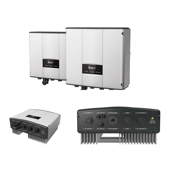
Ac Output Connection
7
Fault Diagnosis and Solutions
Download this manual
INVT BPD
BASIC SETUP MANUAL
Table of
Contents
Previous
Page
Next
Page
1
2
3
4
5
Advertisement
Table of Contents
Need help?
Do you have a question about the BPD0K7 TN AC and is the answer not in the manual?
Ask a question
Questions and answers
Related Manuals for INVT BPD0K7 TN AC
Inverter INVT BPD0K7TN Operation Manual
Pv pumping inverter (75 pages)
Inverter INVT BPD Series Operation Manual
Pv pumping inverter (75 pages)
Inverter INVT BPD2K2TN Operation Manual
Pv pumping inverter (75 pages)
Inverter INVT BPD2K2TNAC Operation Manual
Pv pumping inverter (75 pages)
Inverter INVT BPD1K5 TN AC Setup Manual
Basic setup (13 pages)
Inverter INVT BPD2K2 TN AC Setup Manual
Basic setup (13 pages)
Inverter INVT iMars BG1K5TL Operation Manuals
Imars series grid-tied solar inverter (83 pages)
Inverter INVT iMars BG10KTR Operation Manual
Photovoltaic grid-connected inverter (64 pages)
Inverter INVT iMars BG6KTR Operation Manual
Grid-tied solar inverter (68 pages)
Inverter INVT iMars BG12KTR Operation Manual
Grid-tied solar inverter (68 pages)
Inverter INVT iMars BD3KTL-PS Operation Manual
Energy storage inverter (49 pages)
Inverter INVT iMars BG5KTR Operation Manual
Photovoltaic grid-connected inverter (64 pages)
Inverter INVT BD30KTR-P Manual
150kw-p inverter (54 pages)
Inverter INVT BD Series User Manual
(37 pages)
Inverter INVT BD-RH1 Series User Manual
Hybrid inverters (23 pages)
Inverter INVT GD100-0R4G-SS2-PV Operation Manual
Goodrive100-pv series solar pumping inver ter (86 pages)
This manual is also suitable for:
Bpd1k5 tn ac
Bpd2k2 tn ac
Bpd004 tnac
Bpd2k2 tra s
Bpd004 tra s
Bpd5k5 tra s
Table of Contents
Print
Rename the bookmark
Delete bookmark?
Delete from my manuals?
Login
Sign In
OR
Sign in with Facebook
Sign in with Google
Upload manual
Upload from disk
Upload from URL


Need help?
Do you have a question about the BPD0K7 TN AC and is the answer not in the manual?
Questions and answers