Table of Contents
Advertisement
Quick Links
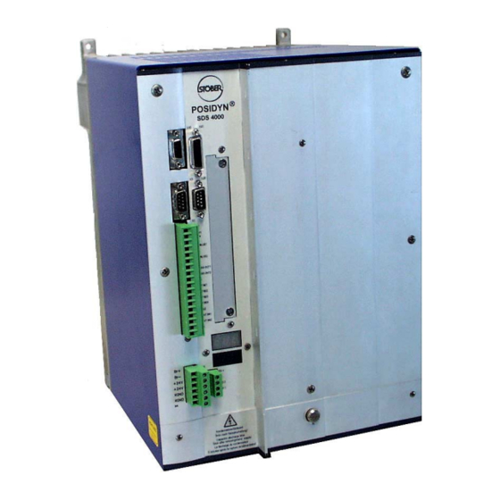
SERVO INVERTER
POSIDYN
®
SDS 4281 / SDS 4481
Supplementary Documentation
Before starting installation and commissioning, it is
essential to read and comply with the installation
®
and commissioning instructions for the POSIDYN
SDS 4000 servo inverter (ID no. 441422) !
POSITIONING CONTROL
SYNCHRONOUS OPERATION
TECHNOLOGY
SV. 4.5
04/2002
Advertisement
Table of Contents

Related Manuals for Stober POSYDYN SDS 4281


Summary of Contents for Stober POSYDYN SDS 4281
- Page 1 SERVO INVERTER POSIDYN ® SDS 4281 / SDS 4481 Supplementary Documentation Before starting installation and commissioning, it is essential to read and comply with the installation ® and commissioning instructions for the POSIDYN SDS 4000 servo inverter (ID no. 441422) ! POSITIONING CONTROL SYNCHRONOUS OPERATION TECHNOLOGY...
-
Page 2: Table Of Contents
POSIDYN SDS 4000 ® Table of Contents 1 NOTES ON SAFETY.............................. 1 2 TECHNICAL SPECIFICATIONS ..........................2 3 PHYSICAL INSTALLATION ........................... 3 ............................3 DIMENSIONAL DRAWING ............................3 INIMUM DISTANCES ............................3 BUILT IN OPTION BOARD ............................3 HIELD CONNECTION 4 ELECTRICAL INSTALLATION.......................... -
Page 3: Notes On Safety
POSIDYN SDS 4000 ® 1. Notes on Safety NOTES ON SAFETY To prevent avoidable problems from occurring during commissioning and/or operation, it is essential to read and comply with this entire instruction manual before starting installation and commissioning. Based on DIN EN 50178 (once VDE 0160), SDS-series servo inverters are defined as electronic power equipment (BLE) for the control of power flow in high-voltage systems. -
Page 4: Technical Specifications
POSIDYN SDS 4000 ® 2. Technical Specifications TECHNICAL SPECIFICATIONS Specification Model 3 SDS 4281 SDS 4481 Type of device (Id.-no. 43481) (Id.-no. 43482) Nominal connected load 28 kVA 48 kVA Nominal current (effective value, ±3%) 40 A 70 A Max. output current (max. of approx. 5 sec, 80 A 140 A ±3%) -
Page 5: Physical Installation
POSIDYN SDS 4000 ® 3. Physical Installation PHYSICAL INSTALLATION DIMENSIONAL DRAWING MINIMUM DISTANCES "mit Stecker" = "with plug" On sides: 55 mm Top/bottom: 100 mm Cabinet depth: 325 mm (min.) Screws: 4 x M6 BUILT-IN OPTION BOARD Installation only by trained STÖBER personnel. Cannot be installed later by the customer. -
Page 6: Electrical Installation
POSIDYN SDS 4000 ® 4. Electrical Installation ELECTRICAL INSTALLATION COMPONENTS OF A SERVO SYSTEM POSIDYN® SDS 4281 POSIDYN® SDS 4481 Controller / PLC 24 V power pack Power filter Fuses Power derating Load resistance Drive contactor Fuses Motor Terminals Lines in bold type are shielded. -
Page 7: Connector Assignment Sds 4281 / Sds 4481
POSIDYN SDS 4000 ® 4. Electrical Installation CONNECTOR ASSIGNMENT SDS 4281 / SDS 4481 X20 Encoder X3 Service X20 Encoder Pin H20=1; 2 H20=3 H20=4 H20=5 Freq.- CLK+ CLK- Freq.+ CLK- CLK+ 1 +8V 1 PGND CANL 6 See table s. -
Page 8: Power Connection
POSIDYN SDS 4000 ® 4. Electrical Installation POWER CONNECTION Terminal strip X4 ® In contrast to POSIDYN SDS 4011 to SDS 4141, the connections for the motor halting brake are located on the 24 V power plug connector and not on the motor plug connector. -
Page 9: Power Filter
POSIDYN SDS 4000 ® 5. Power Filter POWER FILTER Id.-no. L1 Terminals Gnd Bolts 3-EF-42 43477 5 3x42 A 3-EF-75 43478 6 3x75A... -
Page 10: Power Derating
POSIDYN SDS 4000 ® 6. Power Derating POWER DERATING Derating Type Dimensions in mm Weight Id.-no. Phase 43479 ø8 43480 ø8... - Page 12 Visit the STÖBER homepage http://www.stoeber.de Always up-to-date with the latest information on: FDS Tool Catalogs, documentation, installation instructions and much more Sample applications Presented by: STÖBER ANTRIEBSTECHNIK GmbH + Co. KG GERMANY Kieselbronner Strasse 12 · 75177 Pforzheim Postfach 910103 · 75091 Pforzheim Fon +49 (0) 7231 582-0, Fax +49 (0) 7231 582-1000 Internet: http://www.stoeber.de / e-Mail: mail@stoeber.de...
Need help?
Do you have a question about the POSYDYN SDS 4281 and is the answer not in the manual?
Questions and answers