
Related Manuals for Infinity HPS500


Summary of Contents for Infinity HPS500
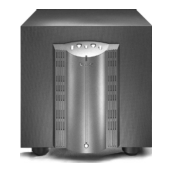
- Page 1 HPS500 High-Current Powered Subwoofer Technical Manual INFINITY SYSTEMS INC. 250 Crossways Park Drive Woodbury, New York 11797 A Harman International Company Rev. A 8/00...
-
Page 2: Table Of Contents
TABLE OF CONTENTS............2 HPS500 POWER SUPPLY PCB........16 CAUTIONS AND WARNINGS..........2 HPS500 LINEAR AMPLIFIER PCB........17 HPS500 SPECIFICATIONS..........3 HPS500 AC POWER & LOW LEVEL INPUT PCB's..18 CONTROLS AND CONNECTIONS........4 HPS500 HI LEVEL INPUT PCB........19 HPS500 CONNECTIONS..........5 HPS500 ELECTRICAL PARTS LIST ......20 OPERATION ..............7 HPS500 INTEGRATED CIRCUIT DIAGRAMS ....24... -
Page 3: Hps500 Specifications
Amplifier/Subwoofer HPS500 HPS500 SPECIFICATIONS Infinity HPS-500 500w Powered Sub Amp SPECIFICATIONS Frequency respose 22Hz - 120Hz Drive Unit 15" Woofer Weight 77.2 lbs./35kg Dimensions (H x W x D) 19 3/4 x 19 x 22 7/16" (502 x 483 x 570mm) -
Page 4: Controls And Connections
Amplifier/Subwoofer HPS500 CONTROLS AND CONNECTIONS AUDIO VIDEO 0° 180° NORMAL DIRECT 150 50 PHASE CROSSOVER GAIN INPUT LEVEL LEVEL HIGHPASS OUTPUT 120Hz 160Hz 80Hz 1. Equalizer - The EQ optimizes subwoofer performance 8. Low Level Input - Main RCA input jacks, recommend for audio or video playback. -
Page 5: Hps500 Connections
Amplifier/Subwoofer HPS500 HPS500 CONNECTIONS If your receiver/processor does not have subwoofer outputs for the left and right channels: RECEIVER/PROCESSOR If your receiver/processor has subwoofer outputs for the left and right channels: NOTE: Some receivers have a single subwoofer output (do not confuse this with a single LFE output as described on the next page). - Page 6 Amplifier/Subwoofer HPS500 HPS500 CONNECTIONS Continued... Ò I f y o u h a v e a D o l b y D i g i t a l o r D T S SUBWOOFER OR receiver/processor with a low-frequency-effect LFE OUTPUT...
-
Page 7: Operation
Turning the Power On do not extend to the lower bass frequencies, set the Plug your HPS500’s AC cord into a wall outlet. Do not low-pass crossover control to a higher setting, between use the outlets on the back of the receiver. -
Page 8: Hps500 Block Diagram
Amplifier/Subwoofer HPS500 HPS500 BLOCK DIAGRAM... -
Page 9: Hps500 Test Set Up And Procedure
Amplifier/Subwoofer HPS500 HPS500 TEST SET UP AND PROCEDURE LEVEL LEVEL HIGHPASS OUTPUT 120Hz 160Hz 80Hz Initial Control Settings 7. Turn on generator and adjust so that speaker level output is 4.0V, 50 Hz. 1. Audio/Video button should be on AUDIO 8. -
Page 10: Disassembly Procedures
Amplifier/Subwoofer HPS500 DISASSEMBLY PROCEDURES Amplifier Removal Woofer Removal Lay the subwoofer on its side on a padded surface, DO NOT ATTEMPT TO PRY THE GRILLE (#10) OUT amplifier facing upwards. OF ITS RECESS. Locate and remove the (2) Allen head screws (#2) at Lay the subwoofer on its side on a padded surface. -
Page 11: Hps 500 (120 & 230 V) Test Procedure
Amplifier/Subwoofer HPS500 HPS 500 (120 & 230 V) TEST PROCEDURE Idle current check, and output stage bias adjustment : Remove and expose amplifier assembly by following instructions on the preceding page. All connectors must remain intact. Locate and disconnect the CD+ connector on the main board; insert a DC Ammeter set to a low range between the two connectors. -
Page 12: Hps500 Cabinet Exploded View
Amplifier/Subwoofer HPS500 HPS500 CABINET EXPLODED VIEW Ref.# Description Part Number Qty. NOT FOR SALE AMPLIFIER ASSEMBLY (120V) NOT FOR SALE AMPLIFIER ASSEMBLY (230V) 900701-008 AMP. MOUNTING SCREWS, MS, BHXS, 8-32 x .5 BLACK 900101-012 BRACKET SCREWS, PB, PPH, #8 x .75"... -
Page 13: Hps500 Amp Assembly Exploded View
Amplifier/Subwoofer HPS500 HPS500 AMP ASSEMBLY EXPLODED VIEW Ref. Ref. Part # Description Part # Description 930042 AMP HOUSING PLASTIC RP0078 KNOB FOR POWER BUTTON HPS500 810066 MET, HTSNK CLIPS RP0076 KNOB FOR POTS 810070 MET, HTSNK LEFT RP0077 KNOB FOR PUSH SWITCH... -
Page 14: Hps500 Input Cup Assembly Exploded View
Amplifier/Subwoofer HPS500 HPS500 INPUT CUP ASSEMBLY EXPLODED VIEW Ref. Part # Description 630031 PCB, INPUT SHIELD HPS500/1K 930035 CUP, OUTER PLASTIC 930039 CUP, INNER PLASTIC FH0010 FUSE, HOLDER PANEL MT RANGLE 1 FS0026 FUSE, 4A 250V 1.25X.25 GLASS HN0015 NUT, HEX KEP #8-32 ZNP... -
Page 15: Hps500 Packing
Amplifier/Subwoofer HPS500 HPS500 PACKING NOTE: For packing and unpacking turn the carton up-side-down. CARTON #333606-001 (120V) #333606-002 (230V) LEFT & RIGHT FOAM #333775-001 (comes as a set) PROTECTIVE FOAM PACKING SHEET HPS500 SURVEY CARD #330033-001 WARRANTY CARD #334085-001 OWNER'S MANUAL... -
Page 16: Hps500 Power Supply Pcb
Amplifier/Subwoofer HPS500 HPS500 POWER SUPPLY PCB... -
Page 17: Hps500 Linear Amplifier Pcb
Amplifier/Subwoofer HPS500 HPS500 LINEAR AMPLIFIER PCB... -
Page 18: Hps500 Ac Power & Low Level Input Pcb's
Amplifier/Subwoofer HPS500 HPS500 AC POWER & LOW LEVEL INPUT PCB's Low Level Component Traces Input PCB Solder Side Traces as shown through the board AC Power Component Traces Solder Side Traces as shown through the board... -
Page 19: Hps500 Hi Level Input Pcb
Amplifier/Subwoofer HPS500 HPS500 HI LEVEL INPUT PCB... -
Page 20: Hps500 Electrical Parts List
Amplifier/Subwoofer HPS500 HPS500 ELECTRICAL PARTS LIST REF # PART # DESCRIPTION REF # PART # DESCRIPTION Resistors Power supply PCB RC0273 RES, ZERO OHM 1/4W R2, R27, R37 RM0180 RES, MF 4.99kW 1/4W 1% Integrated Circuits RC0037 RES, CF 2.0kW... - Page 21 MET, HTSNK CLIP HPS SERIES (FET CLIPS ON THE POWER BOARD) C102 CF0090 CAP, F .022UF 100V 5% 10MMLS 810068 MET, HTSNK HPS500 PWR SUPPLY C108 CF0035 CAP, F .022UF 100V 5% 5MMLS (HEATSINK PLATE FOR THE POWER B) C109, CC0098 CAP, CA .047U 50V 10...
- Page 22 DESCRIPTION REF # PART # DESCRIPTION R39, 60, 121, RC0006 RES, CF 10kW 1/4W 5% 810070 MET, HTSNK LEFT HPS500 FEA/LIN (LEFT SIDE HEATSINK) 122, 123, 124, 146 810071 MET, HTSNK RIGHT HPS500 F/L (RIGHT SIDE HEATSINK) R100 RM0315 RES, MF 2.67kW...
- Page 23 SWITCH, DPDT TOGGLE C/W CAP PC 500086 XFMR, POWER AUDIO YT-6821 MM0025 MISC, PC MT SCREW TERM 6-32 Miscellaneous 630031 PCB, INPUT SHIELD HPS500/1K 930035 CUP, OUTER PLASTIC HPS250 (OUTER PLASTIC CUP) 930039 CUP, INNER PLASTIC HPS500 (INNER PLASTIC CUP)
-
Page 24: Hps500 Integrated Circuit Diagrams
Amplifier/Subwoofer HPS500 HPS500 INTEGRATED CIRCUIT DIAGRAMS U1, U3, U100, U101, U102 OP-AMP QUAD, (TL074, LM324) AMP #3 AMP #4 V CC- IN 4 - IN 4 + IN 3 + IN 3 - OUT 4 OUT 3 U4 - MOC3012 FOTO... -
Page 25: Hps500 Feature Board Schematic
Amplifier/Subwoofer HPS500 HPS500 FEATURE BOARD SCHEMATIC... -
Page 26: Hps500 High Level & Low Level Input And Line Filter Schematics
Amplifier/Subwoofer HPS500 HPS500 HIGH LEVEL & LOW LEVEL INPUT AND LINE FILTER SCHEMATICS... -
Page 27: Hps500 Linear Amplifier Schematic (1 Of 2)
Amplifier/Subwoofer HPS500 HPS500 LINEAR AMPLIFIER SCHEMATIC (1 of 2) -
Page 28: Hps500 Linear Amplifier Schematic (2 Of 2)
Amplifier/Subwoofer HPS500 HPS500 LINEAR AMPLIFIER SCHEMATIC (2 of 2) -
Page 29: Hps500 Power Amplifier Schematic (1 Of 2)
Amplifier/Subwoofer HPS500 HPS500 POWER AMPLIFIER SCHEMATIC (1 of 2) -
Page 30: Hps500 Power Amplifier Schematic (2 Of 2)
Amplifier/Subwoofer HPS500 HPS500 POWER AMPLIFIER SCHEMATIC (2 of 2)
Need help?
Do you have a question about the HPS500 and is the answer not in the manual?
Questions and answers