
Subscribe to Our Youtube Channel
Related Manuals for Infinity HPS 1000


Summary of Contents for Infinity HPS 1000
- Page 1 PRELIMINARY SERVICE MANUAL HPS 1000 POWERED SUBWOOFER Infinity Systems Incorporated 250 Crossways Park Dr. Woodbury, New York 11797...
- Page 2 - CONTENTS - SPECIFICATIONS ………….………….….………………………………………..2 SET-UP GUIDE ………………….…………………………………..…………..3 CONTROLS …………………….………….……………………………………….6 OPERATION ………..…..………………………….…………..……………..7 PARTS LIST ………………..………….…………………………………………….9 SCHEMATICS ………..……...…………………………….…………………...17...
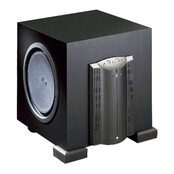
- Page 3 Infinity HPS-1000 1000w Powered Sub Amp SPECIFICATIONS Frequency response 18Hz - 120Hz Drive unit 15" Woofer (2) 15" Passive Radiators Weight 96lbs/43.5kg Dimensions 21 7/8 x 20 7/16 x 23 13/16" (556 x 519 x 605mm) LINE VOLTAGE US 120vac/60Hz...
-
Page 4: Connecting Your Subwoofer
ONNECTING UBWOOFER If your receiver/processor does not have subwoofer outputs for the left and right channels: — — — — ™ B-LINK OUTPUTS INPUTS... -
Page 5: Your Subwoofer
ONNECTING UBWOOFER (Continued) If your receiver/processor has subwoofer outputs for the left and right channels: NOTE: Some receivers have a single subwoofer output (do not confuse this with a single LFE output as described below). In that case, it is recommended that you use a Y connector (not included) to maximize performance. - Page 6 If your receiver/amplifier has preamp output jacks and main input jacks for the left and right channels or you have a separate preamp/processor and power amplifier: This method of hookup can offer the highest level of performance for your complete loudspeaker system.
- Page 7 DENTIFICATION OF RONT ANEL ONTROL ONTROLS (Refer to Figure 2.) 1. EQ: Optimizes subwoofer performance for audio or video playback. 2. Crossover: Controls the frequency below which the subwoofer will begin working. 3. Phase: Reverse/normal switch changes audio-signal polarity. 4. Gain: Controls subwoofer volume level. 5.
-
Page 8: Operation
PERATION ONTROLS Initially set the HPS’ s Gain control to the “O” position. Initially set the HPS’ s Crossover control to the 100Hz position. … OWER Plug your HPS’ s AC cord into a wall outlet. Do not use the outlets on the back of the receiver. Turn on your HPS sub by pressing the power button on the center of the front panel. -
Page 9: A Word Of Advice
ORD OF DVICE The low-frequency Crossover and Volume controls may be set anywhere within their rotation. However, it will be a most unusual circumstance if you have to set the Volume control completely clockwise. This may indicate an unbalanced condition in your system (too much bass), that the system is in an especially large room, or that speaker placement may be incorrect. - Page 10 HPS1000 PARTS LIST AMP ASSEMBLY #333783-001 Power supply PCB Part # Description Ref. Designator Integrated Circuits UA0003 OPAMP, QUAD 14PIN DIL LM324N UP0004 PWM, 8PIN DIL UC3842N Transistors QB0002 TRANS, NPN 40V .6A TO92 2N4401 Q4,Q13,Q14 QB0014 TRANS, PNP MPSA92 TO92 Q5,Q7 QB0017 TRANS, NPN 150V 0.6A 2N5551...
- Page 11 Part # Description Ref. Designator CC0078 CAP, C .22UF 50V 10% .2LS CE0010 CAP, E 22UF 50V 20% 105C .1LS C4,C79 CE0121 CAP, E 470UF 200V 20% 30X25 C30,C31,C32,C33,C34 CF0008 CAP, F 2200PF 100DC 63AC 5% CF0146 CAP, F 6.8UF 250V 10% 27MMLS Diodes DS0001 RECT, 100mA 75V SIGNAL 1N4148T...
- Page 12 Part # Description Ref. Designator RM0089 RES, MF 2K43 1/4W 1% RM0111 RES, MF 17K8 1/4W 1% RM0113 RES, MF 20K0 1/4W 1% R14,R15,R35,R88 RM0114 RES, MF 22K1 1/4W 1% RM0120 RES, MF 30K1 1/4W 1% R7,R47 RM0126 RES, MF 47K0 1/4W 1% RM0147 RES, MF 16K2 1/4W 1% RM0180...
- Page 13 Part # Description Ref. Designator HS0079 SCREW, 6-32 1.5 NYLON PAN USED ON L4 (540130) HW0030 WASHER, FLAT .375OD #8 NYLON USED ON L4 (540130) KS0017 THERMISTOR, 200K @ 25C NTC FINISHING KLUDGE MS0005 SILPAD, .009" .3C/W TO3P USED WITH 5 FETS MS0014 MISC, CERAMIC PLATE TO-220 USED WITH 1 FET...
- Page 14 Part # Description Ref. Designator CF0099 CAP, F .68U 63V 5 C100 CF0119 CAP, F .047UF 100V 5% 5MM C2,C4 CF0045 CAP, F .1UF 63DC 5% 5MMLS C123,C124 CF0090 CAP, F .022UF 100V 5% 10MMLS C122 CF0094 CAP, F .047UF 100V 5% 10MM C102 Diodes DS0001...
- Page 15 Part # Description Ref. Designator RM0103 RES, MF 10K5 1/4W 1% R31,R84 RM0105 RES, MF 12K1 1/4W 1% R111 RM0113 RES, MF 20K0 1/4W 1% R35,R36,R105 RM0120 RES, MF 30K1 1/4W 1% R143 RM0129 RES, MF 53K6 1/4W 1% R14,R29 RM0134 RES, MF 121K 1/4W 1% R145...
- Page 16 Part # Description Ref. Designator MT0003 TERM, KWIKDISC .25 PCB MT CD+,SPKR- MT0023 TERM, FASTON MALE PCMT 187X032 MT0031 TERM, FASTON .205 MALE PC MT SPKR+ SR0017 SWITCH, 2 POLE 2PDT SW3,SW4,SW5 810066 MET, HTSNK CLIP HPS SERIES CLIPS FOR FETS 810072 MET, HTSNK LEFT HPS1000 F/L LEFT SIDE HEATSINK FOR THE F...
- Page 17 Part # Description Ref. Designator HS0072 SCREW, #4 HI-LOW PAN PHIL ZNP USED TO ATTACH THE CABLE TIE HS0073 SCREW, #6 HI-LOW PAN PHIL ZNP 4PC ON FEATURE LINEAR BOARD JC0071 CNCTR, FEM-FEM HARNESS 8PIN 9" FROM CLASS D BD TO FEA/LIN B JC0114C CNCTR, 3PIN MALE/3PIN FEM LOCK AC CONNECT TO JC0114A ON INP...
- Page 18 Part # Description Ref. Designator CF0143 CAP, FY1 4700PF 250V 20 JC0052 CNCTR, RCA QUAD JACK RCA1 JH0063 CNCTR, HEADER 3PIN .1CTR J34,J36 MM0025 MISC, PC MT SCREW TERM 6-32 SR0022 SWITCH, DPDT TOGGLE C/W CAP PC 930035 CUP, OUTER PLASTIC HPS250 OUTER PLASTIC CUP 930043 CUP, INNER PLASTIC HPS1000...
Need help?
Do you have a question about the HPS 1000 and is the answer not in the manual?
Questions and answers