Table of Contents
Advertisement
Quick Links
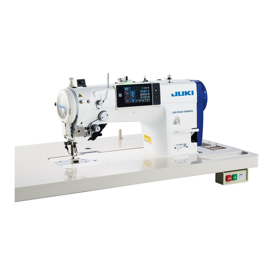
LZ-2290C / X73257
INSTRUCTION MANUAL / PARTS LIST
This Instruction Manual only describes the setup and operation methods for the stitch skipping/double
catching detection device (SD-29) for the LZ-2290C Series of sewing machine.
Refer to the documents (Instruction Manual and Safety Precautions) for the LZ-2290C Series of sewing
machine for descriptions about parts other than the stitch skipping/double caching detection device (SD-29).
Advertisement
Table of Contents

Subscribe to Our Youtube Channel
Related Manuals for JUKI LZ-2290C/X73257


Summary of Contents for JUKI LZ-2290C/X73257
- Page 1 LZ-2290C / X73257 INSTRUCTION MANUAL / PARTS LIST This Instruction Manual only describes the setup and operation methods for the stitch skipping/double catching detection device (SD-29) for the LZ-2290C Series of sewing machine. Refer to the documents (Instruction Manual and Safety Precautions) for the LZ-2290C Series of sewing machine for descriptions about parts other than the stitch skipping/double caching detection device (SD-29).
-
Page 2: Table Of Contents
CONTENTS Preface..........................1 1. Parts supplied with the device (Parts of the SD-29 device) ........2 2. Installing the under cover ....................3 3. Writing the software for electrical components (for a limited time) ......4 4. Assembling the sensor amplifier components ............6 5. -
Page 3: Preface
Preface [ SD-29 ] SD-29 is the device that displays errors on the operation panel to notify the occurrence of below-stated mal- functions including stitching failure. Stitching failure "stitch skipping" has occurred. M640 Stitching failure "needle thread breakage" has Stitch skipping is detected occurred. -
Page 4: Parts Supplied With The Device (Parts Of The Sd-29 Device)
1. Parts supplied with the device (Parts of the SD-29 device) Sensor amplifier components Sensor amplifier asm. (1 piece) Sensor amplifier mounting base asm. (1 piece) Support rod (2 pieces), Washer (4 pieces), setscrew (2 pieces), Ground wire (1 piece) Under cover asm. -
Page 5: Installing The Under Cover
* For the SD-29 (in the case "U220 Stitch skipping and double catching detecting function" is set to "1: Enable"), the maximum sewing speed of the sewing machine is limited to 4000 sti/min. Consequently, the LZ-2290C/X73257 is not provided with the hook cooling fan. (Maximum sewing speed of the stan- dard sewing machine: 5000 sti/min). -
Page 6: Writing The Software For Electrical Components (For A Limited Time)
The software for the standard sewing machine will be interchangeable with the dedicated software after changing its design. At the present, however, it is necessary for you to re-write the software for the electrical components until JUKI completes the change in design. ● Re-writing procedure ①... - Page 7 ⑤ Turning OFF the power to the sewing machine. * Turn OFF the power switch located on the table after the screen as shown in the figure on the left appears on the operation panel. Re-turn ON the power to the sewing machine after the green lamp located on the upper part of the operation panel goes out.
-
Page 8: Assembling The Sensor Amplifier Components
4. Assembling the sensor amplifier components WARNING 1. Be sure to turn OFF the power to the sewing machine for the sake of safety before assembling the sen- sor amplifier components. 2. Be sure to firmly tighten the screws to prevent them from loosening by vibration when the sewing ma- chine is in operation. -
Page 9: Assembling The Sensor Head Components
5. Assembling the sensor head components WARNING 1. Be sure to turn OFF the power to the sewing machine for the sake of safety before assembling the sen- sor amplifier components. 2. Be sure to firmly tighten the screws to prevent them from loosening by vibration when the sewing ma- chine is in operation. -
Page 10: Connecting The Cords (1) - On The Sensor Amplifier Side
6. Connecting the cords (1) - On the sensor amplifier side - WARNING 1. Be sure to turn OFF the power to the sewing machine for the sake of safety before assembling the sen- sor amplifier components. 2. Be sure to firmly tighten the screws to prevent them from loosening by vibration when the sewing ma- chine is in operation. -
Page 11: Connecting The Cords (2) - Sensor Head Side
⑦ Remove the screws (four pieces) from the electri- cal control box to open the cover. ⑧ Connect the connector of sensor junction cord ❾ to the connector of the cords described in the aforementioned step ⑤ . Connect the remaining connector to the CN51 on the CTL PCB mounted inside the electrical control box. - Page 12 ② Secure cord described in the aforementioned step ① with clamp ❸ of the under cover with slackened by approximately 10 mm. If the cord is not sufficiently slackened, the sensor head may break when raising the machine head, or the operation plate ❸...
-
Page 13: Adjusting The Sensor Position
8. Adjusting the sensor position WARNING 1. Be sure to turn OFF the power to the sewing machine for the sake of safety before assembling the sen- sor amplifier components. 2. Be sure to firmly tighten the screws to prevent them from loosening by vibration when the sewing ma- chine is in operation. - Page 14 ④ Place the jig on the under cover. Observe the light receiving section of the sensor (on the surface of the bobbin case) from the mirror of the jig. * If it is hard to see the laser light when using the accessary plated bobbin case, change it with the existing (separately available) non-plated bobbin case [part number: 40125507] to carry out adjust- ment.
- Page 15 ⑥ Adjusting the reflective plate asm. The reflective plate asm. should not come in con- tact with the hook. The reflective plate asm. should not come in con- The reflective plate asm. tact with the feed bar. should be in a position ❻...
-
Page 16: Turning The Sensor
9. Turning the sensor WARNING 1. Be sure to turn OFF the power to the sewing machine for the sake of safety before assembling the sen- sor amplifier components. 2. Be sure to firmly tighten the screws to prevent them from loosening by vibration when the sewing ma- chine is in operation. - Page 17 ⑥ Open the cover of the sensor amplifier. Press the "TUNE" button located on the left side of the amplifier once. * When you press the "TUNE" button, "1Pnt 9999" is displayed on the amplifier. When you release the "TUNE" button, "2Pnt 9999" is displayed on the amplifier.
-
Page 18: Dpc Function
10. DPC function The DPC function is a correction function to help the user to use the SD-29 satisfactorily. (The DPC function works to allow the SD-29 to carry out detection with stability even when the quantity of light received by the sensor varies due to cloth chips or oil gathering on the sensor head, bobbin case sur- face and/or reflective plate.) WARNING Be sur to turn OFF the DPC function before you carry out... - Page 19 The set values given below are the default values (factory-set [ How to set the DPC function ] at the time of shipment). If any of the values is different from the default values given below, change it to the default value. Previous page ❶...
-
Page 20: Solution Viewer Function
11. Solution viewer function The solution viewer is a check function to help the user to use the SD-29 satisfactorily. When the sewing machine actually performs sewing with the condition (thread, material, sewing pattern and the number of revolutions) applied to the sewing process, the solution viewer measures the detection-ON transit time and difference in the quantity of light received (difference in light quantity between ON and OFF states of the detection). -
Page 21: Procedure For Checking The Solution Viewer
11-2. Procedure for checking the solution viewer 1. Place the thread and material you want to use in the sewing process on the sewing machine. 2. Raise the main body of the sewing machine and turn ON the power to the sewing machine. Then, press the ready key (needle bar stop position button 3. -
Page 22: Setting The Functions On The Operation Panel
12. Setting the functions on the operation panel If you want to use the SD-29's detect- ing function, set "S116 Stitch skipping and double catching detecting func- tion" to "Enable". When you have changed the setting of "U220 Stitch skipping and double catching detecting function"... -
Page 23: Set Values Of Memory Switches
12-2. Set values of memory switches Set the number of times of occurrence of stitching failure to be counted and the operation of the sewing ma- chine to be performed until the error is notified. Level 1 Phe- Initial Setting nome- Switch/display Description... - Page 24 Phe- Initial Setting nome- Switch/display Description value range U225 Number of times of detecting stitch The number of times of detecting stitch skipping until 0 to 999 skipping until the stitch skipping mes- the stitch skipping message is displayed and the sew- sage is displayed and the machine is ing machine is immediately stopped.
-
Page 25: Sewing Pattern Data
12-3. Sewing pattern data In the case "U220 Stitch skipping detection function" is set to "1: Enable", "S116 Stitch skipping and double catching detecting function" will be added to the sewing pattern data as described below. Initial setting of "S116 Stitch skipping and double catching detecting function" is "Disable". If you use the SD- 29's detecting function, set the S116 to "Enable". -
Page 26: Flow Of Work By Maintenance Personnel
13. Flow of work by maintenance personnel WARNING 1. Do not tilt or raise the main body of sewing machine with the operation plate held down. Doing so can cause the sensor to move out of position. 2. If the operation plate interferes with the under cover, the sensor sensitivity should be checked as de- scribed in "9. - Page 27 4. Carry out sewing under the solution viewer mode with the condition you want to use in the sewing pro- cess. Check the detection time and the difference in light quantity. Transit time, specification value = 120 μs or more (milliseconds are all acceptable). If the transit time is smaller than 120 μs, the threshold should be increased.
-
Page 28: Procedure For Replacing The Hook And For Adjusting The Hook Timing
13-2. Procedure for replacing the hook and for adjusting the hook timing WARNING 1. Do not tilt or raise the main body of sewing machine with the operation plate held down. Doing so can cause the sensor to move out of position. 2. - Page 29 9. Turn ON the DPC function. * Refer to "10. DPC function" p.16 for the operating procedure. * As long as the display on the amplifier is as shown below at the beginning of sewing (no thread is present on this side of the bobbin case), there is no problem. (The figure given below indicates the state that channel 1 is used.) ❶ "1"...
-
Page 30: Operating And Bobbin-Changing Procedures
14. Operating and bobbin-changing procedures * As long as the display on the amplifier is as shown below at the beginning of sewing (no thread is present on this side of the bobbin case), there is no problem. (The figure given below indicates the state that channel 1 is used.) ❶ "1"... -
Page 31: Method For Changing The Bobbin
14-2. Method for changing the bobbin WARNING 1. Do not tilt or raise the main body of sewing machine with the operation plate held down. Doing so can cause the sensor to move out of position. 2. If the operation plate interferes with the under cover, the sensor sensitivity should be checked as de- scribed in "9. -
Page 32: Method For Unlocking And Locking The Index Plunger (At Two Locations)
14-3. Method for unlocking and locking the index plunger (at two locations) WARNING 1. Do not tilt or raise the main body of sewing machine with the operation plate held down. Doing so can cause the sensor to move out of position. 2. -
Page 33: Parts List
15. Parts list [ SD-29 equipment components ] 1. SD-29 EQUIPMENT COMPONENTS SD -29装置関係 46 54 56 53 52 55 29 27 23 26 25 57 58 59 49 49 24 28 50 51 28 48 48 47 47 48 48... - Page 34 品 名 REF.NO NOTE PART NO D E S C R I P T I O N ベース板 402-24381 BASE_PLATE 反射板組 402-39338 REFLECTOR_ASM ベース板B 402-39329 BASE_PLATE_B 角度調整板 402-24382 ANGLE_ADJUSTMENT_PLATE 位置調整板A 402-24383 POSITION_ADJUSTMENT_PLATE_A 反射シール貼付板 402-24384 REFLECTIVE_SEAL_PASTING_PLATE 位置調整板B 402-24387 POSITION_ADJUSTMENT_PLATE_B 反射板 402-24373 REFLECTOR (0.5) 座金付き六角穴ボルト M3 L=6...
- Page 35 [ X73257 exclusive parts ] 2. X73257 EXCLUSIVE PARTS X 73257専用部品 1 3 2 4 4 6 5 5 品 名 REF.NO NOTE PART NO D E S C R I P T I O N モーター油防板追加工_CS 402-39334 MOTOR_CAP_ADD_CS モーター油防板追加工_CF 402-39331 MOTOR_CAP_ADD_CF モーター土台追加工...
-
Page 36: Optional Parts
16. Optional parts 3. OPTIONAL PARTS COMPONENTS オプション関係 8 9 52 A 1 2 1 4 1 6 23 1 7 1 0 58 22 21 11 1 8 1 3 53 1 5 54 57 A 56 1 9 20... - Page 37 品 名 REF.NO NOTE PART NO D E S C R I P T I O N SD-29ゲージセット 402-50040 SD-29_GAUGE_SET SD-29_ゲージ組 402-50041 SD-29_GAUGE_ASM SD-29_ゲージ 402-27675 SD-29_GAUGE SD-29_ゲージ土台 402-27676 SD-29_GAUGE_BASE ロッカクアナ ボルト M5X0.8 L=30 SM-6053002-TP SCREW M5X0.8 L=30 マグネット 402-39325 MAGNET ミラー 402-39326 MIRROR SD-29_釜冷却セット...
-
Page 38: Additional Function For The Standard Sewing Machine
17. Additional function for the standard sewing machine Along with the development of the SD-29, functions have been added to the standard sewing machine as described below. (Software for the standard sewing machine will be modified) ※ In order to ensure stable sewing with a low tension applied to the thread, the thread tension con- troller unit of this sewing machine is provided with a felt spacer and a tension disk release spring instead of those for the standard sewing machine at the time of shipment. -
Page 39: Correction Of The Shape Length Of Sewing Pattern
17-2. Correction of the shape length of sewing pattern With "S055 Shape length correction" function, data on the shape of sewing pattern such as a rough scallop pattern can be set more minutely as compared with the predecessor machines. "S055 Shape length correction" is the function for correcting the shape length of a sewing pat- tern. -
Page 40: Troubleshooting
18. Troubleshooting Check that the display on the amplifier is as shown below at the beginning of sewing (there is no thread on this side of the bobbin case). (The figure given below indicates the state that channel 1 is used.) ❶ "1"... - Page 41 Q2 False detection occurs. (Error is notified though any stitching failure such as double catching, stich skipping or thread breakage has not occurred.) A. Check the following two items ① and ② in the written order. ① Carry out measurement with the solution viewer. Do you find any problem with respect to the measurement result of the transit time and/or the difference in the quantity of light received? → Refer to"Q1-A ②...
- Page 42 Q3 The quantity of light fails to reach "9999". A. Check the following two items ① , ② , ③ and ④ in the written order. ① Check whether or not any of the below-stated phenomena 1 to 4 has occurred. 1.
- Page 43 Q4 I am worried about the hook that becomes hot. A. When you use this device, it is recommended to minimize the hook oil amount in order to maintain and improve performance of the device. If you worry about the hook heating, use the op- tional part (separately available), "hook cooling device (part number: 40250042) as shown in the figure given below.
- Page 44 Q6 It is difficult to identify the error. A. It is possible to increase the duration of error notification sound (up to 2.5 seconds) with the mem- ory switch. → Refer to "12. Setting the functions on the operation panel" p.20. If you still find it difficult to identify the error even after carrying out the above, use the optional part (separately available), "signal tower set (part number: 40250044).
Need help?
Do you have a question about the LZ-2290C/X73257 and is the answer not in the manual?
Questions and answers