Table of Contents
Advertisement
Quick Links
Advertisement
Table of Contents

Related Manuals for Aqua Lung MDB


Summary of Contents for Aqua Lung MDB
- Page 1 Military BC TECHNICAL MANUAL Rev 10/11...
- Page 2 Aqua Lung International. It may not be distributed through the internet or computer bulletin board systems without prior consent in writing from Aqua Lung International.
-
Page 3: Table Of Contents
coNtENtS INtRoDuctIoN ..................5 GENERAL PREcAutIoNS AND WARNINGS .......... 7 PRoDuct oVERVIEW ................9 SPEcIAL FEAtuRES ................. 9 BC Air Breathing ........................9 Pocket..........................10 Drain plug .......................... 10 AuXILIARY AIR cYLINDER ..............10 Filling the Auxiliary Cylinder....................10 Attaching the Auxiliary Cylinder ..................12 INFLAtIoN mEtHoDS ................ - Page 4 2: toRquE SPEcIFIcAtIoNS ........... 39 tABLE 3: REcommENDED cLEANERS AND LuBRIcANtS ....39 PRocEDuRE A: cLEANING AND LuBRIcAtING ......... 40 EXPLoDED PARtS DIAGRAm ..............41 mDB comPoNENtS ................43 oVERHAuL PARtS KItS ................ 44 tEcHNIcAL DAtA .................. 45 mAINtENANcE NotES ................46...
-
Page 5: Introduction
4. Auxiliary cylinder is full and no leaks are detected. If 3. When instructed to remove an o-ring, use the the MDB fails any of the 4 steps, it should be serviced pinch method (see illustration below) if possible, or by an Aqua Lung trained service technician. - Page 6 (pn 103102) or brass (pn when removing o-rings 944022) o-ring removal tool to prevent damage to the sealing surface. Even a small scratch across an o-ring sealing surface could result in leakage. once an o-ring sealing surface has been damaged, the part must be replaced with new.
-
Page 7: General Precautions And Warnings
WARNING: In the event of an uncontrolled, rapid ascent, it is important to immediately begin venting air from the mDB. continue venting air to slow your ascent rate if neutral buoyancy cannot be re-established. - Page 8 If you have any questions regarding your Buoyancy Compensator or these instructions, contact an Aqua Lung technical Representative...
-
Page 9: Product Overview
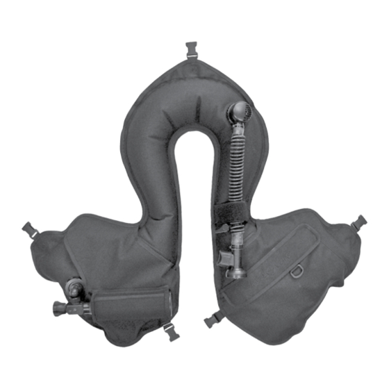
SCUBA, semi-closed circuit or closed circuit rebreathers. The MDB features a single air cylinder attachment that allows you to inflate the vest with compressed breathing air. The air cylinder is equipped with a Groupe d' Etudes et de Re- cherches Sous-Marines (GERS M20) 90 degree connection for use on the jacket. -
Page 10: Pocket
Drain Plug The MDB is equipped with two drain caps located on the back of each lobe of the BC. The caps can be removed to rinse the inside of the bladder. AuXILIARY AIR cYLINDER The auxiliary cylinder is attached to the MDB by means of a threaded hand fitting (Fig. - Page 11 3. Inspect the O-ring at the end of the fill adapter to make sure it is in good condition. Thread the adapter onto the threaded outlet boss on the cylinder valve until finger tight (Fig. 3). check o-ring Fig. 3 4.
-
Page 12: Attaching The Auxiliary Cylinder
8. Close the valve of the supply cylinder and then the valve of the auxiliary cylinder. Slowly purge the relief plug by depressing it down with your finger to relieve the high pressure air trapped in the adapter. -
Page 13: Inflation Methods
DEFLAtIoN mEtHoDS Throughout the course of a dive, it may be necessary to release air from the MDB using one of the two methods described in the following instructions. Each method uses a valve that is in a dif- ferent location. -
Page 14: Deflating Via The Dual Exhaust Valve
Inside the inflator’s corrugated hose is a nylon line that attaches the inflator to the dual valve at the top of the airway assembly. You can vent air from the MDB by firmly pulling straight down on the inflator. Once resistance is felt, only a pull of 7mm (.25 in) is required. The Rapid Exhaust Valve (REV) provides an effective and convenient way to vent air from the BC while in either an upright or face down swimming position (Fig. -
Page 15: Donning And Adjustment Procedures
(Fig.10e) up or down the strap. After adjusting the position of the 3-bar slide, readjust the strap through the quick release buckle. 2. Once the straps are readjusted, don the MDB to make sure the adjustments are correct. Fig. 11... -
Page 16: Pre-Dive Inspection
Fig. 12 Fig. 13 2. Fully inflate the MDB once again and let it sit for 10 minutes to check for leaks and firmness (Fig. 14). WARNING: If you can hear any leaks or if the bladder begins to deflate within 10 min- utes, Do Not attempt to use the mDB until it has received service. - Page 17 3. Inspect all quick release buckles (both male and female ends) that are attached at the top, sides and on the crotch strap of the MDB for cracks, breakage or general damage. Please refer to the diagram in the donning and adjustment procedures section for specific quick release buckle locations (Figs.
- Page 18 5. Verify all hook and loop material is not excessively worn and it is in good working condition (Fig. 21). check Hook / Loop on Pocket Fig. 21 7. Check the dual valve connector, caps and cylinder connectors making sure they are sealed and no air is escaping (Figs.
-
Page 19: Post Dive Care & Maintenance
Avoid repeated or prolonged use in heavily chlorinated water, which can cause the MDB fabric to discolor and decay prematurely. Do not allow the MDB to chafe against any sharp objects or rough surfaces that could abrade or puncture the bladder. Do not set or drop heavy objects such as cylinders or block weights on the MDB. - Page 20 Reinstall the drain caps, cylinder connectors and oral airway. Orally inflate the MDB until it is partially inflated. Store the MDB partially inflated, away from direct sunlight and in a clean, dry area. Do not store in an enclosed space, such as a car trunk, where temperatures may fall below -18ºC...
-
Page 21: Airway Maintenance Procedures
3. Pull back the hose (25) from the mouthpiece body (30). Press note: Before performing any disassembly, refer to the the pin (29) out from one side using a pin punch or similar tool to exploded parts drawing which references all mandatory release the braided nylon cord (24). -
Page 22: Dual Valve Disassembly
Airway Disassembly 3. Remove the stem assembly and spring (33) through the front of the lower inflator housing (32). Remove the mouthpiece (31) from the mouthpiece body (30). DuAL-VALVE Disassembly note: the outer cap is bonded to the body of the dual valve assembly with a non-permanent adhesive. -
Page 23: Oral Inflator Assembly
Before dressing each o-ring with Christo-Lube , check to ® ensure it is clean, supple and free of any blemish. WARNING: use only genuine Aqua Lung parts sub- ® assemblies and components whenever assembling any Aqua Lung product. Do Not attempt to sub- ®... - Page 24 3. Install the diaphragm (36) over the large threaded end of the stem 6. Using needle nose pliers, place the rubber valve (28) flat end up (34) until it rests against the face of the plastic valve (35). Place over the small diameter threads of the stem (34).
-
Page 25: Dual Valve Assembly
Airway Assembly 3. Compress the poppet assembly with the forked end out onto the poppet holding fixture. Using the inflator cord fixture, install the braided nylon cord (24) through the hole in the poppet stem (20) and round the inflator cord post 2 times (Two loops around post DuAL-VALVE and two passes through the stem). -
Page 26: Airway Assembly
Airway Assembly 5. Squeeze the arms of the poppet guide (22) so that the ears fit inside the barrel and press the poppet guide completely inward until the ears snap into place inside their respective holes. Check... - Page 27 4. Insert retaining pin (29) half way into one hole of the mouthpiece body (30). Capture both loop ends of the braided nylon cord (24) using your thumb and index finger facing up, slide the hose (25) back for clearance. Rotate your wrist pointing your thumb and index finger down to form a “Larks Head Knot”...
-
Page 28: Procedures
4. Remove the retaining ring (12) using reversible circlip pliers (pn note: Before performing any disassembly, refer to the 111100) and discard the retaining ring. Remove the handwheel exploded parts drawing, which references all mandatory (11) and o-ring (8) from the connector (7). Discard o-ring (8). -
Page 29: Assembly
Before dressing each o-ring with Christo-Lube , check to ® ensure it is clean, supple and free of any blemish. WARNING: use only genuine Aqua Lung parts, ® sub-assemblies and components whenever assem- bling any Aqua Lung product. Do Not attempt to ®... - Page 30 5. Install a new lubricated o-ring (8) onto the connector (7). Place the 3. Place one small drop of Loctite 414 Superbonder on the bottom handwheel (11) on the connector (7) and secure in place with a new threads of connector base (4).
-
Page 31: Cylinder Valve Maintenance Procedure
cYLINDER VALVE mAINtENANcE 3. Using the modified screwdriver (pn 941586), remove the hand- wheel nut (42), spring (43), handwheel (44) and washer (45) from PRocEDuRES the spindle (50). note: Before performing any disassembly, refer to the exploded parts drawing, which references all manda- tory replacement parts. - Page 32 7. Holding the valve body assembly in a vise, use a 22mm (7/8 this concludes Disassembly of the cylinder Valve. inch) socket (pn 769354) and 3/8" flex handle drive (pn 9-44363) to remove the valve plug (46) from the body (55).
-
Page 33: Assembly
Before dressing each o-ring with Christo-Lube , check to ensure it is clean, supple ® and free of any blemish. WARNING: use only genuine Aqua Lung parts, ® subassemblies and components whenever assem- bling any Aqua Lung product. Do Not attempt to ®... -
Page 34: Cylinder Valve Testing Procedures
FINAL ASSEmBLY AND tEStING 6. Apply a small amount of lubrication to the o-ring (54) and fit onto the valve seat adapter (53). Apply one drop of Loctite 242 to the small threads and screw the valve seat adapter (53) into the body (55) hand tight. - Page 35 3. While holding the dual valve assembly secure, firmly grasp the 6. Manually inflate the BC until it is taut and fully inflated. Press the inflator assembly and pull it in a straight line directly away from push button (38) and then pull down on the oral inflator to ensure the dual valve assembly.
-
Page 36: Bc Patch Kit Instructions
Bc Patch Kit Instructions 3. Apply a generous coat of Weld-On 4784® adhesive to the mate- rial of the BC surrounding the hole or tear. Allow this preliminary coat to set for at least twenty four hours. - Page 37 tABLE 1: LISt oF tooLS PART # DESCRIPTION APPLICATION 129198 Adjustable Face Removal/Installation of Oral Inflator Push Button (38) Spanner 101215 Tank Fill Charging cylinder Adapter 944022 O-ring Tool Kit Removal/Installation of O-rings (Brass) 103102 O-ring Tool (Plastic, 5 pk) 820466 Christo-Lube Lubrication of O-rings/Parts...
- Page 38 1: LISt oF tooLS (coNtINuED) PART # DESCRIPTION APPLICATION FC34A 27mm (1-1/16 inch) Crowfoot Removal/Installation of Valve Body (55) Cord Hook Installing Braided Nylon Cord (24) through Spiral Hose (25) (Locally Manufactured) Poppet Fixture Removal/Installation of Braided Nylon Cord (24)
- Page 39 30 Nm (22 ft.lbs) 840919 Adapter, valve seat (53) 10 Nm (89 in.lbs) tABLE 3: REcommENDED cLEANERS AND LuBRIcANtS LuBRIcANt/cLEANER APPLIcAtIoN SouRcE Aqua Lung, PN 820466 or Lubrication Technologies christo-Lube mcG 111 All o-rings 310 Morton Street Jackson, OH 45640 (800) 477-8704 cAutIoN: Silicone rubber requires no lubrication or preservative treatment.
-
Page 40: Procedure A: Cleaning And Lubricating
PRocEDuRE A: cLEANING AND LuBRIcAtING cleaning Brass and Stainless Steel Parts 1. Preclean in warm, soapy water* using a nylon bristle tooth brush. 2. Thoroughly clean parts in an ultrasonic cleaner filled with soapy water. If there are stubborn de- posits, household white distilled vinegar (acetic acid) in an ultrasonic cleaner will work well. -
Page 41: Exploded Parts Diagram
101328 Pin, sealing, non-mag 101341 862476 Collar, swivel Retaining ring, non-mag 101344 850443 15.7mm *Aqua Lung France Part Numbers 101239 Airway complete Key # PN Description 15309 Gasket, connector seal 42742 Dual valve body assembly, ACME 1 15714 Gasket, REOP... - Page 42 840163 O-ring 15 Nm 840921 Spindle 840199 Oldham 228365 Seat, valve 840919 Adapter, valve seat 850219 O-ring 840917 Body 850228 O-ring 840955 Cylinder .43L 220 BAR, black, alu 1 *Aqua Lung France Part Numbers Loctite 242 10 Nm 30 Nm...
-
Page 43: Mdb Components
Description 15309 Gasket, Connector seal 101239 Airway Complete, Atlantis, Non-mag 840558 Connector, Assy, Bouee Polyvalente 841335 Vest Only , MDB, Packaged 15665 Cap, Universal Connector 762956 Removable Chest Strap, 1.0", Atlantis 762957 Kit, Waist Strap, 1.5", Atlantis 840970 Cylinder, .43L w/ Valve (Export) -
Page 44: Overhaul Parts Kits
840489 840971 Kit, cylinder (Export) Key # PN* Description 850218 O-ring Washer 840523 840163 O-ring 228365 Seat, valve 850219 O-ring 850228 O-ring *Aqua Lung France Part numbers Key # PN Description 42611 Bladder Repair Kit *Aqua Lung France Part Numbers... -
Page 45: Technical Data
DAtA Annual maintenance The MDB is subject to annual maintenance. All parts listed in the overhaul parts kit must be replaced annually, even if they appear to be in good condition. composition • 1 Vest only (Key #60) is constructed of heavy duty urethane coated 1000 denier black material. -
Page 46: Maintenance Notes
NotES... -
Page 47: Warranty Information
® ™ Aqua Lung America warrants to the original purchaser for a period of one year from the date of purchase that the product will be free from defects in material and workmanship; provided that it receives normal use, proper care, and prescribed dealer service subject to those restrictions stated below. This limited warranty is extended only to the original purchaser for purchases made from an authorized Aqua Lung ®... - Page 48 Military BC 2340 Cousteau Court • Vista, CA 92081 Phone (760) 597-5000 • Fax (760) 597-4900 www.aqualung.com/militaryandprofessional ©2011 Aqua Lung International Literature PN 18205 Rev. 10/11...
Need help?
Do you have a question about the MDB and is the answer not in the manual?
Questions and answers