Nice LP21 Manual
Hide thumbs
Also See for LP21:
- User, installation and safety instructions (2 pages) ,
- Quick start manual (4 pages)
Table of Contents
Advertisement
Quick Links
LP21/LP22
1
Safety instructions
Availability of documents
The Operating manual must be available at all times. The instructions must be read and understood before
the device is used for the first time, and adhered to at all times.
Service only by trained electricians
All work on the device (assembly, connection, commissioning, decommissioning, maintenance, repair,
measurements and settings) may only be carried out by qualified electricians with relevant training on the
prevention of accidents.
Intended use
The device may only be used for the purpose intended by the manufacturer. Consult the chapter relating to
intended use.
Improper use
The device is subject to the manufacturer's warranty conditions valid at the time of purchase. The
manufacturer will not accept any responsibility for unsuitable or incorrect manual or automatic parameter
settings performed on a device or the inappropriate use of a device.
Improper repairs
Repairs may only be performed by the manufacturer. Failure to comply will endanger the safety of the device
and renders the warranty null and void.
Permitted voltages
The voltage supply must meet the requirements for safety extra-low voltage ("Circuits and power sources of
limited power" SELV).
Regulations on electrical voltage
Users of devices which come into contact with electrical voltage must comply with the valid regulations.
These are in particular, but with no claim to completeness, EN 60335, EN 60065, EN 50110, and the fire and
accident-prevention regulations.
Comply with national regulations
All work on the device and its installation must be carried out in accordance with the specifications of the
national electrical regulations and local regulations.
Essential safety equipment
The device may not be used as a safety component as defined by the Machinery Directive 2006/42/EG, the
Construction Products Regulation 305/2011/EU or other safety regulations. Systems with a hazard potential
require additional safety equipment!
Pag. 1 a 37
LP21/LP22 Installation instructions en
Sensors
Advertisement
Table of Contents

Related Manuals for Nice LP21


Summary of Contents for Nice LP21
- Page 1 The device may not be used as a safety component as defined by the Machinery Directive 2006/42/EG, the Construction Products Regulation 305/2011/EU or other safety regulations. Systems with a hazard potential require additional safety equipment! Pag. 1 a 37 LP21/LP22 Installation instructions en Sensors...
-
Page 2: Proper Use
Areas of application are systems in the areas of traffic engineering, door and barrier controller, parking and tunnel monitoring as well as traffic light systems. The traffic detectors of the LP21/LP22 series are intended for installation in a controller cabinet or a similar housing. -
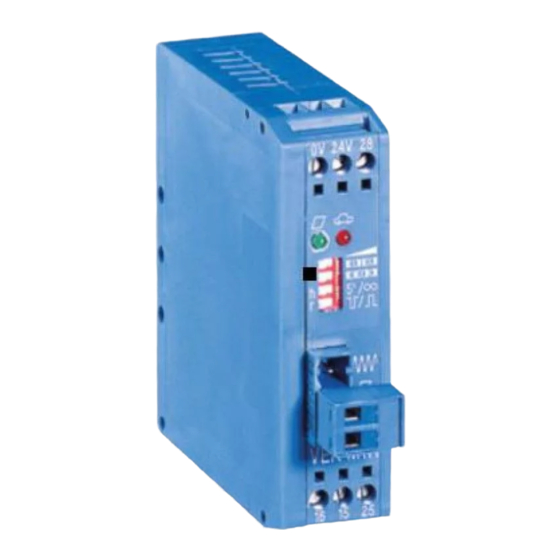
Page 3: Product Overview
LP21/LP22 Product overview Housing dimensions Fig.1: LP21/LP22 side view Fig.2: LP21/LP22 front view Pag. 3 a 37 LP21/LP22 Installation instructions en Sensors... -
Page 4: Device Components
LP21/LP22 Device components Fig.3: Traffic detector LP21/LP22 Index Component Description Loop channel LEDs 1 (red + blue) Status indicators for the loops and the detector DIP switch 1 Basic settings for the detector Loop channel LEDs 2 (red + blue) -
Page 5: Technical Data
12 ms (independent of loop channels) Maximum speed for vehicles • presence detection Max. 200 km/h • direction detection (dual-channel variants) Max. 200 km/h (at loop head distance of 2 m) Pag. 5 a 37 LP21/LP22 Installation instructions en Sensors... - Page 6 Relays with contacts that are prestressed in this manner can only reliably switch currents over 100 mA! 3) Terminal block data Grid dimension 5.0 mm, conductor cross-section 0.25 - 2.5 mm², AWG 24-12 Pag. 6 a 37 LP21/LP22 Installation instructions en Sensors...
-
Page 7: Product Description
Systems with high switching frequency The use of detectors with digital outputs is recommended for systems with a high switching frequency. A restricted switching cycle limits the operational life of relay contacts. Pag. 7 a 37 LP21/LP22 Installation instructions en Sensors... -
Page 8: Product Characteristics
LP21/LP22 Product characteristics The traffic detectors have the following properties: • 1 loop channel (LP21) or 2 loop channels (LP22) • 2 potential-free relay outputs with changeover contact • 8-pole DIP switch for configuration • 4-pole DIP switch for advanced configuration (LP22) •... - Page 9 If no induction loop is connected to the loop channel, this corresponds to a loop break error status. Once a loop error has been detected, the loop channel switches off. This may cause the available operating modes to be restricted, for example direction detection. Pag. 9 a 37 LP21/LP22 Installation instructions en Sensors...
-
Page 10: Description Of Connections
The induction loops are connected to the orange terminal blocks as shown in the illustration. Induction loop channel 1 connections Induction loop channel 2 connections (dual-channel variant LP22) Fig.4: Loop connections (orange) Pag. 10 a 37 LP21/LP22 Installation instructions en Sensors... -
Page 11: Signal Outputs
COM1 Common contact to output 1 (COM1) or output 2 COM2 (COM2) Normally closed contact to output 1 (NC1) or output 2 (NC2) Fig.5: Relay connections 1 (yellow) and 2 (red) Pag. 11 a 37 LP21/LP22 Installation instructions en Sensors... - Page 12 1. Place on the device from above with the groove on the top hat rail and lock the clip underneath. 2. Check that it is sitting securely. → The detector is ready for commissioning. Pag. 12 a 37 LP21/LP22 Installation instructions en Sensors...
-
Page 13: Connecting The Power Supply
1. Comply with the warnings and safety instructions for the external device. 2. Follow the manufacturer’s instructions on wiring the outputs on the external device. → The power cable is connected to the power source. Pag. 13 a 37 LP21/LP22 Installation instructions en Sensors... - Page 14 1. Comply with the warning and safety instructions for the external device. 2. Follow the manufacturer’s instructions on wiring the outputs on the external device. → The relay outputs are connected to the signal outputs on the external device. Pag. 14 a 37 LP21/LP22 Installation instructions en Sensors...
- Page 15 The two cable ends leading from the induction loop to the detector (loop supply line) must be twisted with min. 20 strokes/m. • Avoid dividing the cable. Should is be necessary to divide the cable, protect the clamp points against moisture penetration with cast resin collars. Pag. 15 a 37 LP21/LP22 Installation instructions en Sensors...
- Page 16 4. Insert up to 5 mm of stripped cable into the slot on the side of the terminal block and fasten. 5. Tighten the screw. 6. If necessary, insert the terminal block back into the orange 4-pole socket. → The induction loops are firmly attached with no exposed wires. Pag. 16 a 37 LP21/LP22 Installation instructions en Sensors...
- Page 17 1. Define the settings with the DIP switches. 2. Switch on the power supply to the detector. → The LP21/LP22 series detectors automatically run a test of the induction loops as well as a frequency alignment. → The detector is ready for operation when the blue LEDs are continuously lit. There is more information in the chapter on LED indicators.
-
Page 18: Description Of Functions
(see Flash code illustrated example) Tab.6: LED signal colours Key to LED symbols Lit up Flashing Frequency LED flash code following a frequency alignment Fig.8: LED display of loop frequency Pag. 18 a 37 LP21/LP22 Installation instructions en Sensors... -
Page 19: Dip Switch Settings
Evaluation logic of the direction of travel when loop is covered according to the specific application (read the operating instructions!) Tab.7: Description of the settings 8.2.1 DIP switch assignment of the LP21 variants The single-channel variants have an 8-pole DIP switch for configuring the detector. Designation Function... - Page 20 Output 2 Continuous signal on entering Edge 2 on leaving Output inverted Inv. Out 1 Output not inverted Output not inverted Inv. Out 2 Output inverted Tab.9: Settings via DIP switch (LP21) Pag. 20 a 37 LP21/LP22 Installation instructions en Sensors...
- Page 21 DIP2 Label Function Dir. Mode Direction detection Dir. Logic Direction logic Inv. Out 1 Output signal 1 inversion Inv. Out 2 Output signal 2 inversion Tab.11: DIP switch 2 occupancy (standard) Pag. 21 a 37 LP21/LP22 Installation instructions en Sensors...
- Page 22 Inv. Out 1 Output not inverted Output not inverted Inv. Out 2 Output inverted Presence Dir. Mode Direction Continuous signal 2 Dir. Logic Wrong-way driver 1 Tab.12: Settings via DIP switch (LP22) Pag. 22 a 37 LP21/LP22 Installation instructions en Sensors...
-
Page 23: Reset Button
This document refers to the default settings or default values defined by the manufacturer. The factory settings of customer variants may differ from the manufacturer’s specifications. Please observe the instructions on the device, as well as the documents supplied with it. Pag. 23 a 37 LP21/LP22 Installation instructions en Sensors... - Page 24 Sensitivity (f/f) (Sense a) (Sense b) 0.01 % Level high (highest sensitivity) Level medium-high 0.16% Level medium-low 0.64% level medium-low (factory setting) Tab.14: Sensitivity settings Pag. 24 a 37 LP21/LP22 Installation instructions en Sensors...
- Page 25 Loop inductivity range In the event of loop inductivity outside the recommended range, the available frequency range may be restricted. DIP (frequency) Frequency step low (factory setting) High Tab.15: Loop frequency settings Pag. 25 a 37 LP21/LP22 Installation instructions en Sensors...
- Page 26 DIP (hold time) Hold time infinite 5 min Tab.16: Hold time settings (LP21/LP22) Setting output mode (signal type) Various output modes (signal types) can be set for the outputs. WARNING Switching off the direction logic (2 channel version) The direction logic must be switched off to set the output mode, i.e.
- Page 27 Set impulse duration The default impulse duration is 200 ms. DIP (edge 2) Impulse time when the loop is driven past (factory setting) when the loop is freed up Tab.19: Output impulse time Pag. 27 a 37 LP21/LP22 Installation instructions en Sensors...
- Page 28 It should be noted that the counter overflows at 65,535 (2 ) and is automatically erased. • The counter readings are not protected against power failure! Direction detection Switched off (factory settings) Switched on Tab.21: Setting direction detection Pag. 28 a 37 LP21/LP22 Installation instructions en Sensors...
- Page 29 Recording single vehicles and Loop free Leaving Loop 2 manoeuvring. Queues should not occur. Parking bay Direction- Direction 1 For short entrances and exits dependent Direction 2 Tab.23: Overview of direction logic Pag. 29 a 37 LP21/LP22 Installation instructions en Sensors...
- Page 30 Tab.24: Key to direction logic You can find information on the detailed functions for different traffic situations in the following section. “Single vehicle” direction logic 9.8.1 Fig.10: Single vehicle direction logic Pag. 30 a 37 LP21/LP22 Installation instructions en Sensors...
- Page 31 LP21/LP22 “Queue” direction logic 9.8.2 Fig.11: Queue direction logic “Wrong-way driver” 1 direction logic 9.8.3 Fig.12: Wrong-way driver 1 direction logic Pag. 31 a 37 LP21/LP22 Installation instructions en Sensors...
- Page 32 LP21/LP22 “Wrong way driver 2” direction logic 9.8.4 Fig.13: Wrong-way driver 2 direction logic “Manoeuvring” 1 direction logic 9.8.5 Fig.14: Manoeuvring 1 direction logic Pag. 32 a 37 LP21/LP22 Installation instructions en Sensors...
- Page 33 LP21/LP22 “Manoeuvring” 2 direction logic 9.8.6 Fig.15: Manoeuvring 2 direction logic Pag. 33 a 37 LP21/LP22 Installation instructions en Sensors...
- Page 34 LP21/LP22 “Wrong-way driver in queue” direction logic 9.8.7 Fig.16: “Wrong-way driver in queue” direction logic Pag. 34 a 37 LP21/LP22 Installation instructions en Sensors...
- Page 35 9.8.8 Fig.17: Cross traffic direction logic NOTE False counts All logics except logic PB in direction 1 deliver false counts in this traffic situation, because they count entries instead of exits! Pag. 35 a 37 LP21/LP22 Installation instructions en Sensors...
- Page 36 Correct counting also with cross traffic • Correct counting with queues • Correct counting also when a single vehicle is manoeuvring • No manoeuvring is permitted to take place in a queue! Pag. 36 a 37 LP21/LP22 Installation instructions en Sensors...
-
Page 37: Maintenance And Servicing
7. Pull the cable out of the mounting slots. → The detector is disassembled. 12 Disposing of the product At the end of its service life, dispose of the product in accordance with the valid legal specifications. Pag. 37 a 37 LP21/LP22 Installation instructions en Sensors...
Need help?
Do you have a question about the LP21 and is the answer not in the manual?
Questions and answers