Advertisement
Quick Links
5 - OUTPUTS AND LED INDICATORS
5.1 - Operating principle of the relays
The factory setting establishes that both relays function according to the principle of standby current. The
operation principle of the relay can be set according to the following table by using jumpers, if fitted on the
card. In this regard, the housing of the detector must be opened carefully (see table 7).
- Warning! On the card there are components which are sensitive to static energy. When
working with the device open, appropriate precautions are required. Do not touch the compo-
nents or conductors! The warranty will be nullified for damages caused by improper handling!
Platine
Table 7
Detector status
Relay operating principle
1*)
Tension is off
Free loop
Output
Loop fault
✱ ) Factory setting
Relay
Jumper
Position
1-2
•
JP1
2-3
•
•
1
1-2
•
JP3
2-3
•
•
1-2
•
JP2
2-3
•
•
2
1-2
•
JP4
2-3
•
•
5.2 - LED indicators
The green LED indicates that the detector is ready for operation. The red LED, depending on the occupa-
tion status of the loop, indicates the activation of the relay output (see table 8).
Table 8
Green LED loop control
Red LED loop status
Off
Off
Flashing light
Off
On
Off
On
On
Off
On
5.3 - Loop frequency indication
About 1 s after the adjustment of the detector, the loop frequency is indicated by flashing signals on the
green LED. First of all, the 10 kHz location of the frequency value will be displayed. For each frequency
value of 10 kHz, the green LED of the detector channel will flash once. After 1 sec. the 1 kHz position will
be displayed in the same manner. If the value at the position of 1 kHz is '0' the LED will flash 10 times.
The 1 kHz position flashes are slightly shorter than the 10 kHz position flashes.
Example of 57 kHz loop frequency:
6 - ELECTRICAL CONNECTIONS
– Incorrect connections can cause faults or hazards; therefore ensure that the specified con-
nections are strictly observed and performed by experienced and qualified personnel.
– Hook up the unit with the electrical power shut off.
2
3
4
Relay function
•
Normally open contact
Normally closed contact
•
Working current principle
7 - DISPOSAL OF THE PRODUCT
Quiescent current principle
This product constitutes an integral part of the automation system, therefore it must be dis-
•
Normally open contact
posed of together with it. As in installation, also at the end of product lifetime, the disassembly and
Normally closed contact
scrapping operations must be performed by qualified personnel. This product is made up of different types
of material, some of which can be recycled while others must be disposed of. Seek information on the
•
Working current principle
recycling and disposal systems envisaged by the local regulations in your area for this product category.
Quiescent current principle
– Some parts of the product may contain polluting or hazardous substances which, if disposed
of into the environment, constitute serious environmental and health risks.
Detector status
8 - TECHNICAL SPECIFICATIONS
No power voltage
Note: • All technical specifications stated herein refer to an ambient temperature of 20° C (± 5° C). • Nice S.p.A.
reserves the right to apply modifications to products at any time when deemed necessary, maintaining the same
Frequency indication or adjustment
intended use and functionality.
The detector is ready, free loop
• Dimensions: 79 x 22.5 x 90 mm (H x W x L without plug) • Protection type: IP40 • Power supply: 24
The detector is ready, occupied loop
V
no condensation • Loop inductivity: 25-800 μH, recommended 100-300 uH • Frequency range: 30-
Loop fault
130 kHz in 2 steps • Sensitivity: from 0.01% to 0.64 % (Δf/f) in 4 levels - from 0.02% to 1.3% (ΔL/L) •
Delay: 5 min or uninterrupted • Electric power line of the loop: max. 250 m • Loop resistance: max.
20 Ohm (including power line) • Relay: 250 mA / 24 V
100 ms • Signal duration: > 200 ms • De-energise delay: normally 50 ms • Connection: Screw ter-
minals (power supply, relay) – Snap-on terminal clamps (loops connection)
Tens
Units
1 s
5x 10 kHz
7x 1 kHz
- Warning!
Table 9
Description
Power input
Relay 1
Relay 2
Loop 1 and Loop 2
Installation examples
1
3
Gate
2m
1m
1m
Roadway
Roadway
2
0,8 m
4
B
C
A
0,8 m
2m
Roadway
Roadway
As indicated by the symbol, the product may not be disposed of as domestic waste. Sort the
materials for disposal, according to the methods envisaged by current legislation in your area,
or return the product to the retailer when purchasing an equivalent product.
tion may include the application of serious fines in the event of improper disposal of
this product.
/
±10 % max. 2.0 W • Operation temperature: -20°C to +70°C • Air humidity: max 95% with
/
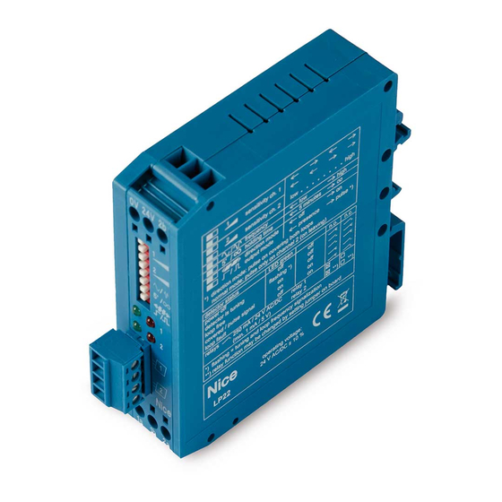
Nice
LP22
Connection
User, installation and
0 V
24 V
safety instructions
1a
1b
2a
2b
Connector block with 4 - poles
5
5 - 8 mm
A
B
C
D
Fig. 1 - Recommended for cars,
lorries, buses
D
Fig. 2 - Recommended for motor-
bikes and bicycles
Fig. 3 - Applications requiring low
sensitivity at the side
Fig. 4 - (A) Floor (B) Twisted wire
(C) Groove (D) Loops
Fig. 5 - (A) Sealant (B) Groove
(C) Twine (D) Loops
IS0426A00MM_04-11-2016
- Local legisla-
(min.1 mA/5 V) • Energise delay: normally
EN
Nice S.p.A.
Via Pezza Alta, 13
31046 Oderzo TV Italy
www.niceforyou.com
info@niceforyou.com
Advertisement

Related Manuals for Nice LP22


Summary of Contents for Nice LP22
- Page 1 No power voltage Note: • All technical specifications stated herein refer to an ambient temperature of 20° C (± 5° C). • Nice S.p.A. reserves the right to apply modifications to products at any time when deemed necessary, maintaining the same...
- Page 2 When switching on the power supply voltage, the detector will adjust the loop frequency. If there are brief outages in voltage (< 0.1 s), no new adjustment will take place. The inductive loops detector LP22 is a system used for detecting vehicles by Relay 1 means of inductive loops with the following characteristics: Relay 1 Signal “on”...
Need help?
Do you have a question about the LP22 and is the answer not in the manual?
Questions and answers