Table of Contents
Advertisement
Advertisement
Table of Contents

Related Manuals for Motorline professional ZUMA

Summary of Contents for Motorline professional ZUMA
- Page 1 ZUMA ZUMA USER / INSTALLER'S MANUAL v1.0 REV. 12/2021...
-
Page 2: Table Of Contents
AMOUNT OF SPRINGS resulting from the uncontrolled disposal of waste, separate INSTALLATION OF SPRINGS (ZUMA 4 / ZUMA 6) these items from other types of waste and recycle them BOOM ASSEMBLY (ZUMA 4 / ZUMA 6) - Page 3 01. SAFETY INSTRUCTIONS GENERAL WARNINGS • Children shouldn’t play with the product or opening devices to avoid the motorized door or gate from being triggered involuntarily. • This manual contains very important safety and usage information. very important. Read all instructions carefully before beginning the WARNINGS FOR TECHNICIANS installation/usage procedures and keep this manual in a safe place that it can be consulted whenever necessary.
- Page 4 01. SAFETY INSTRUCTIONS RESPONSABILITY September 2009. • Attach the permanent label for the manual release as close as possible • Supplier disclaims any liability if: to the release mechanism. • Product failure or deformation result from improper installation • Disconnect means, such as a switch or circuit breaker on the electrical use or maintenance! panel, must be provided on the product’s fixed power supply leads in •...
-
Page 5: Automatism
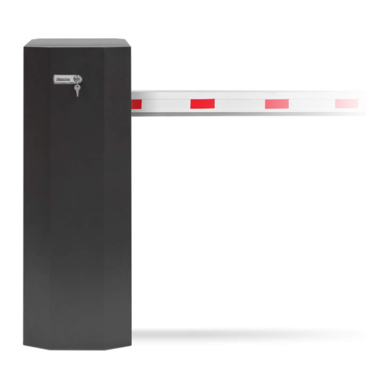
02. AUTOMATISM 02. AUTOMATISM TECHNICAL CHARACTERISTICS INSTALLATION COMPONENTS ZUMA is an electromechanical barrier developed to control vehicle access to private, industrial or commercial areas. Automatism technical specifications: • Barrier boom ZUMA 4 ZUMA 6 ZUMA 8 • MC60BR Control • Operating power... -
Page 6: Dimensions
02. AUTOMATISM DIMENSIONS ZUMA 4 / ZUMA 6 ZUMA 8 • • 220mm 132mm 450mm 416mm 370mm 370mm 300mm 270mm... -
Page 7: Remove The Door 6A
02. AUTOMATISM 02. AUTOMATISM REMOVE THE DOOR MANUAL OPENING / CLOSING This barrier allows free access to the interior, to facilitate the installation and maintenance process of In case of an emergency or during the installation/adjustment phase of the barrier, it may be the product. -
Page 8: Installation
• CREATE FOUNDATION Make a hole 400mm (or greater) in depth and with the following measurements: ZUMA 4 | ZUMA 6: 370(A) x 470(B)mm ZUMA 8: 400(A) x 550(B)mm Fill with concrete and smooth the top. Apply the barrier to the foundation, with the fixing bolts in place, to ensure they are securely secured (see page 8A). -
Page 9: Automatism Installation
• ADJUST BARRIER POSITION drawing. *Once fixed to the ground, the ZUMA is prepared to allow a position adjustment of a few millimeters. Adjustment is made by rotating the barrier in relation to its center. Check that the foundation is perfectly level before applying the barrier. -
Page 10: Spring Position 9A
• 1xM16 on top (rod end plate) If you order ZUMA without specifying the position of the boom, it will be mounted on the right (DX). If the boom is not in the desired position, follow the instructions on page 10 to reverse the... -
Page 11: Installation Of Springs (Zuma 4 / Zuma 6)
03. INSTALLATION INSTALLATION OF SPRINGS (ZUMA 4 / ZUMA 6) If the springs are on the wrong side for the intended boom direction (see diagram on page CHANGE FROM 2 TO 1 SPRING • 9A), you must reverse the position of the springs on the rotation lever. -
Page 12: Boom Assembly (Zuma 4 / Zuma 6)
03. INSTALLATION BOOM ASSEMBLY (ZUMA 4 / ZUMA 6) CHECK BOOM SUPPORT POSITION • A • Fit the boom support taking into account the information presented in the board on the left. B • Tighten the side screws to secure the support to the shaft. -
Page 13: Installation Of Springs (Zuma 8)
Follow the instructions indicated on page 11 and making the association with the numbers in the drawing below, proceed with the installation of the springs in the ZUMA 8. drawing below, proceed with the assembly of the boom in the ZUMA 8. -
Page 14: Fixing Boom Supports
03. INSTALLATION FIXING BOOM SUPPORTS • DEFINE EXTENDABLE BOOM LENGTH • ADJUST SUPPORT (FIXED) HEIGHT If the height of the support arm is out of step with the height of the boom, you will need to adjust the You must now establish the length of it so that you can then place the support, as shown in the height of the arm. -
Page 15: Adjust The Springs
03. INSTALLATION ADJUST THE SPRINGS Before adjusting the springs, manually place the boom in the vertical position so that the springs are in Hold the threaded shaft with a pliers so that the position of least tension (see page 5B). it does not rotate, and keep tightening the adjustment female until each spring is stretched the distance mentioned in the table on page 15. -
Page 16: Adjustment Tables
03. INSTALLATION ADJUSTMENT TABLES • LEVER HOLES Hole 1 Hole 2 Hole 2 Hole 1 ZUMA 4 / ZUMA 6 BOOM ZUMA 8 BOOM • • SINGLE BOOM SINGLE BOOM 6000 5500 5000 4500 4000 3500 3000 8000 7500 7000... -
Page 17: Test Spring Adjustment 16A
03. INSTALLATION 03. INSTALLATION TEST SPRING ADJUSTMENT POWER SUPPLY CABLE *The power wiring from the ground must be connected directly to the fuse located at the The motor must remain unlocked to carry out the adjustment test. bottom of the barrier. PHASE 1 Pass the power cables coming from the ground to the fuse. -
Page 18: Stops Adjustment 17A
The stops present on the barrier are visible in the image below. The ZUMA rotation lever has limit switch micros that allow you to define the end of the opening and • They consist of 2 adjustment screws (one on each side of the barrier) fixed to the base as well as its 2 closing operations. -
Page 19: Connections
04. CONNECTIONS CONNECTION SCHEME (ZUMA 4 / ZUMA 6) • MC60 Control board (Interior of the barrier) LAMP MOT1 • Security Band (Optional) LAMP MOT1 BATT • Transformer • Photocells 230Vac/115Vac 120W Max. COM NC/ • Fuse 230Vac: 2A • Limit switches... - Page 20 04. CONNECTIONS CONNECTION SCHEME - THTSIG15LEDN MODULE (ZUMA 8) • MC60 Control board (Interior of the barrier) • Module THTSIG15LEDN • Power supply 12V+ GI RGI LAMP MOT1 BATT • Transformer 230Vac/115Vac 120W Max. • Twilight sensor • Photocells • Fuse...
- Page 21 04. CONNECTIONS CONNECTION SCHEME - MODULE MP106 (ZUMA 8) • MC60 Control board (Interior of the barrier) RG B LAMP MOT1 BATT • MP106 Module • Power supply • Transformer • Connector 230Vac/115Vac (On the back 120W Max. of the MP106 module) •...
-
Page 22: Troubleshooting
05. TROUBLESHOOTING INSTRUCTIONS FOR FINAL CONSUMERS / SPECIALIZED TECHNICIANS Anomaly Procedure Behavior Procedure II Find out the origin of the problem • Barrier • Make sure you have • Still not working • Consult a specialized 1 • Remove the frontal door from A) It has 24V: diagnosis and repair.
Need help?
Do you have a question about the ZUMA and is the answer not in the manual?
Questions and answers