
Related Manuals for OBELUX Medium-Intensity 2000cd compact Series

Summary of Contents for OBELUX Medium-Intensity 2000cd compact Series
- Page 1 Obelux Medium-Intensity 2000cd compact series manual Medium-intensity 2,000cd red aviation obstruction light ICAO Medium-Intensity Type B/C FAA L-864, L-885 NVG Compliant Infrared 850nm...
-
Page 2: Table Of Contents
Medium-Intensity 2000cd compact series manual Page 2 of 21 CONTENTS ABOUT THIS PRODUCT ............................4 ICAO ..........................4 MODELS PRODUCT CODES ........................... 5 MODELS PRODUCT CODES .............................. 6 RODUCT HIGHLIGHTS SAFETY INSTRUCTIONS ............................9 ............................9 ENERAL CONSIDERATIONS ..........................9 NVIRONMENTAL CONSIDERATIONS ............................ - Page 3 Medium-Intensity 2000cd compact series manual Page 3 of 21 Changelog Version Date Description Author 02.01.2020 Document created. 19.05.2020 Release 05.10.2020 Updated product codes, heater Acronyms and Abbreviations Federal Aviation Administration Flashes Per Minute Global Positioning System ICAO International Civil Aviation Organization...
-
Page 4: About This Product
Page 4 of 21 1 ABOUT THIS PRODUCT Obelux MI compact series LED obstruction lights provide 2,000cd color aviation red light and Night Vision Goggle (NVG) compliant infrared (850 nm) light. Both Stand-alone and Modbus operation are supported. In Stand-alone mode, no external controllers are required to run the light. In Modbus operation, the light is controlled with an Obelux controller as a part of an aviation light system. -
Page 5: Faa Models Product Codes
Medium-Intensity 2000cd compact series manual Page 5 of 21 1.2 FAA models product codes Order code Output Operating Photocell Alarm RS-485 / voltage relay Modbus MI-FAA-AC-2KR-IR-B[-10] 2,000cd L-864, 100- L-885 240VAC MI-FAA-AC-2KR-IR-X[-10] 2,000cd L-864, 100- L-885 240VAC MI-FAA-DC-2KR-IR-B[-10] 2,000cd L-864,... -
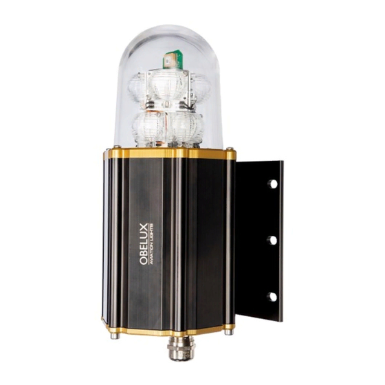
Page 6: Product Highlights
Medium-Intensity 2000cd compact series manual Page 6 of 21 1.3 Product highlights Figure 1: Main functional parts of light head 1. Location of photocell and GPS (do not cover) 2. Spirit level 3. Location of cable glands (M20 (2 pcs), M25 (2 pcs)) Factory installation: ... - Page 7 Medium-Intensity 2000cd compact series manual Page 7 of 21 Figure 2: Main PCB of a light head (AC version) © Obelux Oy 2020 Technical information in this document is subject to change without notice.
- Page 8 Medium-Intensity 2000cd compact series manual Page 8 of 21 Figure 3: Main PCB with E, EF and IO add-on cards © Obelux Oy 2020 Technical information in this document is subject to change without notice.
-
Page 9: Safety Instructions
Obelux aviation obstruction lights are Class 2M LED devices. This class is safe for accidental viewing under all operating conditions. However, it may not be eye-safe for a person who deliberately stares into the LED beam by overcoming their natural aversion response to the very bright light. -
Page 10: Installation
Medium-Intensity 2000cd compact series manual Page 10 of 21 3 INSTALLATION 3.1 Device installation Install the obstruction light to selected mounting point using quality-made fasteners. Level the light using a spirit level (bubble level) if necessary. Tighten bolts and nuts. The light has 6 holes for M8 bolts on the mounting plate. -
Page 11: Mains In/Out (Ac Versions)
Medium-Intensity 2000cd compact series manual Page 11 of 21 3.2.1 Mains In/Out (AC versions) Mark Description Information Live terminal Connect the mains power supply Live (brown) wire into this pole. Neutral terminal Connect the mains power supply Neutral (blue) wire into this pole. -
Page 12: Chaining Lights
Medium-Intensity 2000cd compact series manual Page 12 of 21 3.2.5 Chaining Lights Figure 6. Chaining light heads Figure 7. Distributing power and data to next light head of the network (AC version) Figure 8: Distributing power and data to next light head of the network (DC version) When chaining the RS-485 connector, note the maximum conductor size of 1.5mm²... -
Page 13: Operation
GPS lock. Modbus mode: In this mode, the light is being controlled with an additional Obelux controller. If connection is lost to the controller, the light will keep working on its own. It will use its internal photocell and GPS to synchronize flashing and determine the time of day. -
Page 14: Icao Models
Medium-Intensity 2000cd compact series manual Page 14 of 21 4.1 ICAO models 4.1.1 ICAO Stand-alone mode (basic model) Flashing mode is selected with DIPs 1-3. DIP switch Flashing mode Night 2,000cd red, ICAO (flashing, check DIPs 4-5) 2,000cd red and infrared, ICAO (flashing, check DIPs 4-5) *... -
Page 15: Icao Stand-Alone Mode
Medium-Intensity 2000cd compact series manual Page 15 of 21 4.1.2 ICAO Stand-alone mode Flashing mode is selected with DIPs 1-3. DIP switch Flashing mode Night 2,000cd red, ICAO (flashing, check DIPs 4-5) 2,000cd red and infrared, ICAO (flashing, check DIPs 4-5) *... -
Page 16: Faa Models
Medium-Intensity 2000cd compact series manual Page 16 of 21 4.2 FAA models 4.2.1 FAA Stand-alone mode (basic model) DIP switch Flashing mode Night 2,000cd red and infrared (flashing) * 2,000cd red (flashing) Reserved Reserved Reserved Reserved Reserved Reserved DIP switch... -
Page 17: Faa Stand-Alone Mode
Operating mode Stand-alone * Modbus * Factory default 4.3 Modbus mode The light is in Modbus mode when DIP8 is on. Light is being controlled with an Obelux controller. DIP switch Operating mode Stand-alone Modbus Configuration DIP switches 1-4 are used to give the light a RS-485 bus address. Duplicate addresses on the same bus are not allowed. -
Page 18: Test Mode
Medium-Intensity 2000cd compact series manual Page 18 of 21 DIP switch Modbus Address Address 01 Address 02 Address 03 Address 04 Address 05 Address 06 Address 07 Address 08 Address 09 Address 10 Address 11 Address 12 Address 13 Address 14... -
Page 19: Master Light Mode
Medium-Intensity 2000cd compact series manual Page 19 of 21 The light can be dimmed by using DIP6 and DIP7. Dimming is light brightness as percentage of full power. Note that the light stay in test mode despite DIP7 is turned off. -
Page 20: Heater Operation
Do not exceed maximum operating voltage. Mains power supply input is protected with overvoltage protection circuit that is tuned to stated operating voltage range. No Modbus data connection to Obelux controller • Check DIP settings. Check that light has a correct Modbus address and that there are no conflicting addresses. -
Page 21: Spare Parts
Medium-Intensity 2000cd compact series manual Page 21 of 21 • Too many RS-485 termination resistors (120ohm) on the same RS-485 communication bus. Only the last light on the bus should have the termination resistor in use. • Check Modbus data wiring.