Advertisement
Quick Links
Advertisement

Related Manuals for Alto MS1


Summary of Contents for Alto MS1
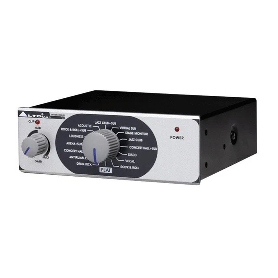
- Page 1 MODEL: MS1...
-
Page 2: Table Of Contents
CONTENT 1. INTRODUCTION ................1 2. TECHNICAL SPECIFICATION ............1 3. BLOCK DIAGRAM ................2 4. SCHEMATIC DIAGRAM..............3 5. PCB LAYOUT..................4 6. TEST PROCEDURE................5 7. EXPLODED VIEW & MECHANICAL PARTS LIST......1 5 8. BOM ....................17... -
Page 3: Introduction
1. INTRODUCTION 16 effects preset 2-channel input and output connectors are compatible with balanced JACK Front panel LED indicator for clip and power on Accurate level control 2. TECHNIACAL SPECIFICATION Connectors 1/4”jack Type RF filtered, servo balanced input AUDIO INPUT Impedance 30 Kohm balanced, 22 Kohm unbalanced Max. -
Page 4: Block Diagram
3. BLOCK DIAGRAM - 2 -... -
Page 5: Schematic Diagram
4. SCHEMATIC DIAGRAM - 3 -... -
Page 6: Pcb Layout
5. PCB LAYOUT - 4 -... -
Page 7: Test Procedure
6. TEST PROCEDURE The Finished Products Test First: Use VP-7724 to test 1. Set the encoder to FLAT (encoder setting: 0000), INPUT/OUTPUT use 1/4 TRS BAL jack to connect LCH IN, LCH/RCH OUT, plug in POWER&CLIP LED wires(semi product), the red POWER LED lights up. - Page 8 8. Cut off input signal, when output noise and GAIN VR are minimum, the output noise is less than-95dBu(Please select the corresponding filter), when the GAIN VR is maximum, the output noise is less than -78dBu, at the same time, make sure the variations of the waveform are normal when turning the GAIN VR.
- Page 9 - 7 -...
- Page 10 - 8 -...
- Page 11 - 9 -...
- Page 12 - 10 -...
- Page 13 - 11 -...
- Page 14 - 12 -...
- Page 15 - 13 -...
- Page 16 - 14 -...
-
Page 17: Exploded View & Mechanical Parts List
7. EXPLODED VIEW & MECHANICAL PARTS LIST - 15 -... - Page 18 MECHANICAL PARTS LIST No. Part No. Description Specification 1 MA05666 ZC-panel MS1 ALTO_V1.3 2 SA00053 LED φ3 HK05843 K-PCB P-MS1-DIP 4 MB04491 ZC-rear board MS1 ALTO_V1.1 5 NI00502 self-adhere foot cushion φ10.5*5mm(RF-011) 6 NI00002 T-plastic nut-HC00108 accessories φ7/16"*G20/15*4.8 7 ME00081 T-nut-HI00107 φ7...
-
Page 19: Bom
8. BOM No. Part No. Description Specification Remark HK05843 PC board P-MS1-DIP HK06476 PC board P-MS1-SMD RD00125 SMD fixed resistor 1/10W 1.0MΩ ±5% 0603 R67,R68,R69,R70 RD00085 SMD fixed resistor 1/10W 1.5KΩ ±5% 0603 RD00116 SMD fixed resistor 1/10W 100KΩ ±5% 0603... - Page 20 FILTER LF-22UH(WAH TAYI) L1,L2,L3,L4 57 SA00088 Schottky barrier diode 1N5817 D3,D4 58 HA01933 jump 2.5mm C60,C62 59 MA05666 panel MS1 ALTO_V1.3 60 MA05641 panel 61 AE00343 solvent No.330 62 AE00177 paint-RS 4866 63 MA05563 panel-RS-ACT MS1 130.5*44*14.5_V1.4 64 MI01297 panel 2.1*44*14.5*130.5_V1.1...
- Page 21 φ2.5*1000mm 87 NI00502 self-adhere foot cushion φ10.5*5.0 88 HJ00002 dessicant 89 NB04289 inner case MS1 ALTO_V1.1 90 NB04291 barrier MS1 164*84mm _V1.0 91 NB04290 barrier MS1 215*183mm _V1.1 92 HA05010 wire-RS φ6.3 STCO*φ4*2C*1250mm 93 TG00195 adaptor-RS 230V/50Hz_AC15V/200mA_EI-41_UL CSA 94 NA00120 PE bag 0.04t*220*200mm...
Need help?
Do you have a question about the MS1 and is the answer not in the manual?
Questions and answers